These pages are generated from the same sources as the controlled PDF documents. The PDF is the official, numbered copy; each page links to the download portal (https://downloads.nex-s01.uavlas.com).
This is the multi-page printable view of this section. Click here to print.
Product Library
Datasheets, interface control documents and operation manuals for shipping UAVLAS products.
- 1: ULS Blitz Protocol
- 2: ULS-DeCoNet
- 3: ULS-DeCoNet Blitz Protocol
- 4: ULS-DeCoNet CAN Transport
- 5: ULS-DeCoNet UART Transport
- 6: ULS-Heli-G2
- 6.1: ULS-Heli-G2 Datasheet
- 6.2: ULS-Heli-G2 Interface Control Document
- 6.3: ULS-Heli-G2 Operation Manual
- 6.4: ULS-Heli-G2 Precision Landing System
- 6.5: ULS-Heli-G2 Precision Landing System
- 7: ULS-Heli-G3
- 7.1: ULS-Heli-G3 Datasheet
- 7.2: ULS-Heli-G3 Interface Control Document
- 7.3: ULS-Heli-G3 Operation Manual
- 8: ULS-OnNet
- 8.1: ULS-OnNet Datasheet
- 9: ULS-ProCopter
- 9.1: ULS-ProCopter Datasheet
- 9.2: ULS-ProCopter Interface Control Document
- 9.3: ULS-ProCopter Operation Manual
- 9.4: ULS-ProCopter Precision Landing System
- 9.5: ULS-ProCopter Precision Landing System
- 10: ULS-XCopter-G2
- 10.1: ULS-XCopter-G2 Datasheet
- 10.2: ULS-XCopter-G2 Interface Control Document
- 10.3: ULS-XCopter-G2 Operation Manual
- 11: ULS-XSpot
- 11.1: ULS-XSpot Datasheet
- 11.2: ULS-XSpot Interface Control Document
- 11.3: ULS-XSpot Operational Manual
- 12: ULS-XSpot-G3
1 - ULS Blitz Protocol
Production
1.1 - ULS Blitz Types and Description
Interface Documentation ULSDC-PBDS031025, version 1.0.1
ULSDC-PBDS031025 · version 1.0.1 · issued November 3, 2025
The numbered PDF is the controlled copy: download it from the portal.
Overview
The protocol used by devices for configuration is proprietary and is described in other documents. However, the protocol implements the possibility of transmitting messages (Blitz messages) that can be used by the user to control the device and obtain information. These messages are universal, and the format describes the data that is transmitted by various devices in our system connected to a single network.
Use CMD=6 to send Blitz messages.
In this document, the CAN protocol is specified. RS485 is used to implement custom protocols that can be defined in the future.
ULS-DECONET CAN Bus Protocol Frame Format
flowchart LR
  A[Sender Device] --> B[GLOBAL]
  B --> C[CMD = 6]
  C --> D[ID]
  D --> E[dsn_lid]
  E --> F[msg_id]
  F --> G[Blitz Payload data <= 8 bytes]
  G --> H[Receiver Device]
The CAN protocol uses the following frame structure:
| Field | Description |
|---|---|
| GLOBAL | Flag used to send packets over several local networks |
| CMD | Command field (Use CMD=6 to send Blitz messages) |
| ID | Packet sender ID (local id src_lid for local packets and device id for global packets src_did) |
| dsn_lid | Destination local ID address |
| msg_id | Message ID used to identify Blitz packet types |
Table: CAN Protocol Frame Fields
Status Bit Definitions
Most messages include a status byte with the following bit definitions:
| Bit | Flag | Description |
|---|---|---|
| 0 | ULS_STATUS_RX_CARRIER_OK | IR signal detected |
| 1 | ULS_STATUS_RX_SQ_OK | Signal quality OK |
| 2 | ULS_STATUS_RX_POS_OK | Position estimated |
| 3 | ULS_STATUS_RX_VEL_OK | Velocity estimated |
| 4 | ULS_STATUS_RX_GU_IMU_OK | Ground Unit IMU OK |
| 5 | ULS_STATUS_RX_MRX_OK | MRX message received (secondary receiver) |
| 6 | ULS_STATUS_RX_MRXDATA_OK | MRX Yaw and Distance calculated OK |
Table: Status Bit Definitions
Message list by device
Message Types
XCG1 Raw Measurement (0x0010)
Message ID: ULS_BLITZ_MSG_ID_XCG1_RX_RAW_MEASURMENT (0x0010)
Structure: __uls_blitz_xcg1_rx_raw_measurmet
| Field | Type | Description |
|---|---|---|
| status | uint8_t | Status bits (see Status Bit Definitions above) |
| d | uint8_t | Distance in 10 cm increments |
| aX | int16_t | Angular information X-axis, proportional [-30000 = -30°, +30000 = +30°] |
| aY | int16_t | Angular information Y-axis, proportional [-30000 = -30°, +30000 = +30°] |
| oF | int8_t | Sensor offset Forward in cm |
| oR | int8_t | Sensor offset Right in cm |
Table: XCG1 Raw Measurement Message Structure Usage: Legacy raw measurement data. Message generated by receiver each time it decode signal from transmitter. Client can capture this frame to get receivers raw data. Do not send this type of message to Bus.
Senders list (this message are generated by):
- ULSDV-XC-RX-G1 - ULS-XCopter receiver (generation 1).
- ULSDV-XC-RX-G2 - ULS-XCopter-G2 receiver (generation 2).
- ULSDV-XS-RXM - ULS-XSpot master receiver.
- ULSDV-XS-RXS - ULS-XSpot slave receiver.
- ULSDV-HL-RXM - ULS-Heli master receiver.
- ULSDV-HL-RXS - ULS-Heli slave receiver.
- ULSDV-PC-RX - ULS-ProCopter receiver.
Receivers list (this message is consumed by):
- Ground control stations (for monitoring)
- Debug/diagnostic tools
- Data logging systems
Raw Measurement (0x0011)
Message ID: ULS_BLITZ_MSG_ID_RX_RAW_MEASURMENT (0x0011)
Structure: __uls_blitz_msg_rx_raw_measurmet
| Field | Type | Description |
|---|---|---|
| status | uint8_t | Status bits (see Status Bit Definitions above) |
| counter | uint8_t | Message counter for tracking |
| aX | int16_t | Angular information X-axis [-180° to +180°] |
| aY | int16_t | Angular information Y-axis [-180° to +180°] |
| distance | uint16_t | Distance measurement |
Table: Raw Measurement Message Structure Angular Conversion Formula:
degrees = (value_int16 * 180.0f) / 32767.0f
Usage: Measurement data generated by receiver each time when signal from transmitter decoded.
Senders list (this message are generated by):
- ULSDV-XC-RX-G1 - ULS-XCopter receiver (generation 1).
- ULSDV-XC-RX-G2 - ULS-XCopter-G2 receiver (generation 2).
- ULSDV-XS-RXM - ULS-XSpot master receiver.
- ULSDV-XS-RXS - ULS-XSpot slave receiver.
- ULSDV-HL-RXM - ULS-Heli master receiver.
- ULSDV-HL-RXS - ULS-Heli slave receiver.
- ULSDV-PC-RX - ULS-ProCopter receiver.
Receivers list (this message is consumed by):
- Autopilot systems (Ardupilot, PX4)
- Ground control stations
- External navigation computers
- Data logging systems
Position in TX Frame (0x0012)
Message ID: ULS_BLITZ_MSG_ID_RX_POS_IN_TX_FRAME (0x0012)
Structure: __uls_blitz_msg_rx_pos_in_tx_frame
| Field | Type | Description |
|---|---|---|
| status | uint8_t | Status bits (see Status Bit Definitions above) |
| counter | uint8_t | Message counter for tracking |
| posX | int16_t | Position X-coordinate in transmitter frame (cm) |
| posY | int16_t | Position Y-coordinate in transmitter frame (cm) |
| posZ | int16_t | Position Z-coordinate in transmitter frame (cm) |
Table: Position in TX Frame Message Structure Usage: 3D position data relative to the transmitter coordinate system. Generated by receiver after calculating position from raw measurements.
Senders list (this message is generated by):
- ULSDV-XC-RX-G1 - ULS-XCopter receiver (generation 1).
- ULSDV-XC-RX-G2 - ULS-XCopter-G2 receiver (generation 2).
- ULSDV-XS-RXM - ULS-XSpot master receiver.
- ULSDV-XS-RXS - ULS-XSpot slave receiver.
- ULSDV-HL-RXM - ULS-Heli master receiver.
- ULSDV-HL-RXS - ULS-Heli slave receiver.
- ULSDV-PC-RX - ULS-ProCopter receiver.
Receivers list (this message is consumed by):
- Autopilot systems (Ardupilot, PX4)
- Ground control stations
- External navigation computers
MRX Information (0x0013)
Message ID: ULS_BLITZ_MSG_ID_RX_MRX (0x0013)
Structure: __uls_blitz_msg_rx_mrx
| Field | Type | Description |
|---|---|---|
| status | uint8_t | Status bits (see Status Bit Definitions above) |
| counter | uint8_t | Message counter for tracking |
| yaw | int16_t | Yaw angle [-180° to +180°] |
| distance | uint16_t | Distance measurement in cm |
Table: MRX Information Message Structure Usage: Multi-receiver (MRX) information for secondary receiver data. Generated when multiple receivers calculate relative orientation.
Senders list (this message is generated by):
- ULSDV-XS-RXM - ULS-XSpot master receiver (when paired with slaves).
- ULSDV-HL-RXM - ULS-Heli master receiver (when paired with slaves).
Receivers list (this message is consumed by):
- Autopilot systems (for yaw correction)
- External navigation computers
- Ground control stations
DACS Information (0x0014)
Message ID: ULS_BLITZ_MSG_ID_RX_DACS (0x0014)
Structure: __uls_blitz_msg_rx_dacs
| Field | Type | Description |
|---|---|---|
| status | uint8_t | Status bits (see Status Bit Definitions above) |
| counter | uint8_t | Message counter for tracking |
| yaw | int16_t | Yaw angle [-180° to +180°] |
| distance | uint16_t | Distance measurement |
| yawContinuous | int16_t | Continuous yaw angle ±32768° |
Table: DACS Information Message Structure Usage: DACS (Directional Angle Calculation System) data with continuous yaw tracking. Advanced multi-receiver mode with unwrapped yaw angle.
Senders list (this message is generated by):
- ULSDV-XS-RXM - ULS-XSpot master receiver (DACS mode).
- ULSDV-HL-RXM - ULS-Heli master receiver (DACS mode).
Receivers list (this message is consumed by):
- Autopilot systems (for continuous yaw tracking)
- External navigation computers
- Ground control stations
Ground IMU Measurement (0x0020)
Message ID: ULS_BLITZ_MSG_ID_GIMU_MEASUREMENT (0x0020)
Structure: __uls_blitz_msg_gimu_data
| Field | Type | Description |
|---|---|---|
| status | uint8_t | Status bits (see Status Bit Definitions above) |
| counter | uint8_t | Message counter for tracking |
| roll | int16_t | Roll angle [-180° to +180°] |
| pitch | int16_t | Pitch angle [-180° to +180°] |
| yaw | int16_t | Yaw angle [-180° to +180°] |
Table: Ground IMU Measurement Message Structure Angular Conversion Formula:
degrees = (value_int16 * 180.0f) / 32767.0f
Usage: Ground unit IMU (Inertial Measurement Unit) orientation data. Provides transmitter orientation for coordinate system transformation.
Senders list (this message is generated by):
- ULSDV-XC-TX-G1 - ULS-XCopter transmitter (generation 1).
- ULSDV-XC-TX-G2 - ULS-XCopter-G2 transmitter (generation 2).
- ULSDV-XS-TX - ULS-XSpot transmitter.
- ULSDV-HL-TX - ULS-Heli transmitter.
- ULSDV-PC-TX - ULS-ProCopter transmitter.
Receivers list (this message is consumed by):
- Ground control stations (for transmitter monitoring)
IMU Override (0x0030)
Message ID: ULS_BLITZ_MSG_ID_XX_TXC_IMU_OVERRIDE (0x0030)
Structure: __uls_blitz_msg_xx_txc_imu_override
| Field | Type | Description |
|---|---|---|
| control | uint8_t | Control bits (see Control Bits below) |
| counter | uint8_t | Message counter for tracking |
| roll | int16_t | Override roll angle [-180° to +180°] |
| pitch | int16_t | Override pitch angle [-180° to +180°] |
| yaw | int16_t | Override yaw angle [-180° to +180°] |
Table: IMU Override Message Structure Control Bits:
| Bit | Description |
|---|---|
| 0 | SET Roll - Enable roll angle override |
| 1 | SET Pitch - Enable pitch angle override |
| 2 | SET Yaw - Enable yaw angle override |
| 3-7 | Reserved |
Table: IMU Override Control Bits Angular Conversion Formula:
degrees = (value_int16 * 180.0f) / 32767.0f
Usage: Override IMU data on ground unit for external orientation control. Allows external IMU/compass to replace internal sensors.
Senders list (this message is sent by):
- External control PC/computer
- Autopilot systems (for transmitter orientation override)
- Ground control stations
Receivers list (this message is consumed by):
- ULSDV-XC-TX-G2 - ULS-XCopter-G2 transmitter (generation 2).
- ULSDV-XS-TX - ULS-XSpot transmitter.
- ULSDV-HL-TX - ULS-Heli transmitter.
- ULSDV-PC-TX - ULS-ProCopter transmitter.
Magnetometer Override (0x0031)
Message ID: ULS_BLITZ_MSG_ID_XX_TXC_MAG_OVERRIDE (0x0031)
Structure: __uls_blitz_msg_xx_txc_mag_override
| Field | Type | Description |
|---|---|---|
| control | uint8_t | Control bits (see Control Bits below) |
| counter | uint8_t | Message counter for tracking |
| mx | int16_t | Magnetic field X-component |
| my | int16_t | Magnetic field Y-component |
| mz | int16_t | Magnetic field Z-component |
Table: Magnetometer Override Message Structure Control Bits:
| Bit | Description |
|---|---|
| 0 | SET override - Enable magnetometer override |
| 1-7 | Reserved |
Table: Magnetometer Override Control Bits Magnetic Field Conversion Formula:
mag_value = (value_int16 * 1.0f) / 32767.0f
Usage: Override magnetometer data on ground unit for external compass control. Allows external magnetometer to replace internal compass.
Senders list (this message is sent by):
- External control PC/computer
- Autopilot systems (for compass override)
- Ground control stations
- External magnetometer systems
Receivers list (this message is consumed by):
- ULSDV-XC-TX-G2 - ULS-XCopter-G2 transmitter (generation 2).
- ULSDV-XS-TX - ULS-XSpot transmitter.
- ULSDV-HL-TX - ULS-Heli transmitter.
- ULSDV-PC-TX - ULS-ProCopter transmitter.
Implementation Notes
Packed Structures: All structures use
__attribute__((packed))to ensure no padding bytes are added by the compiler.Endianness: The protocol assumes little-endian byte order for multi-byte fields.
Message Counters: Most messages include a counter field for packet ordering and loss detection.
Angular Precision: Angular measurements use 16-bit signed integers with specific scaling factors for different ranges.
Distance Units: Distance measurements may use different units (cm, 10cm increments) depending on the message type.
2 - ULS-DeCoNet
Production
2.1 - ULS-DeCoNet Protocol Interface Control Document
ICD ULSDC-PBICD011125, version 1.0.5
ULSDC-PBICD011125 · version 1.0.5 · issued November 13, 2025
The numbered PDF is the controlled copy: download it from the portal.
Introduction
Purpose
The ULS-DeCoNet (ULS Devices Connection Network) protocol is a comprehensive communication protocol designed for Ultra-precise Location Systems (ULS). It provides a robust, hierarchical network architecture for connecting ULS devices across multiple transport mediums including UART and CAN bus.
Scope
This protocol defines:
- Device discovery and network management
- Object-oriented data exchange
- System control and configuration
- Firmware update mechanisms
- Multi-hop routing capabilities
- Blitz sensor data transmission
Key Features
- Multi-transport Support: UART (with various framing modes) and CAN bus
- Automatic Device Discovery: Dynamic network topology with automatic ID allocation
- Hierarchical Addressing: Support for up to 63 local devices per interface
- Multi-hop Routing: Packet forwarding through intermediate nodes
- Object-based Data Model: Structured access to device parameters and data
- Permission System: Read/write/protected access control for objects
- Firmware Update: Secure bootloader mode with signature verification
- Low Overhead: Optimized for embedded systems with limited resources
Terminology
| Term | Description |
|---|---|
| DID | Device ID - Logical identifier for devices on a network segment (0-63) |
| LID | Local ID - Synonym for DID |
| CID | Connection ID - Identifies which connection interface (0-3) |
| HB | Heartbeat - Periodic keep-alive message |
| NM | Network Management - Protocol layer for device discovery |
| CN | Connection - Higher-level protocol for data exchange |
| Blitz | Fast sensor data messaging subsystem |
| MRX | Multi-Receiver eXtension - Secondary receiver support |
| GIMU | Ground IMU - Inertial Measurement Unit on transmitter |
| TXC | Transmitter Control - Ground unit control interface |
Protocol Architecture
Protocol Stack
block-beta
  columns 1
  A["Application Layer\n(Device Objects, Blitz Messages, Config)"]
  B["Connection Layer (CN)\n(Object Access, System Commands, Routing)"]
  C["Interface Layer (IF)\n(Network Management, Device Discovery)"]
  D["Framing Layer\n(UART: ESC/COBS, CAN: Multi-frame)"]
  E["Physical Layer\n(UART, CAN/FDCAN)"]
Design Principles
- Layered Architecture: Clear separation of concerns between protocol layers
- Transport Agnostic: Core protocol independent of physical medium
- Efficient Framing: Multiple framing modes optimized for different scenarios
- Scalable Addressing: Support for hierarchical and flat addressing schemes
- Robust Error Handling: CRC protection and timeout-based error recovery
- Plug-and-Play: Automatic device discovery and ID allocation
OSI Layer Model Mapping
The ULS-DeCoNet protocol maps to the OSI reference model as follows:
| OSI Layer | ULS-DeCoNet Component | Responsibility |
|---|---|---|
| 7. Application | ULSObject, ULSDBase, Blitz Messages | Device-specific data, sensor measurements, configuration |
| 6. Presentation | Data Structures (packed structs) | Data formatting, byte ordering (little-endian) |
| 5. Session | ULSBusConnection | Connection establishment, session management |
| 4. Transport | CN Protocol Layer | Reliable message delivery, routing, flow control |
| 3. Network | IF Protocol Layer | Addressing, device discovery, network management |
| 2. Data Link | Framing (ESC/COBS/CAN) | Frame delimiting, error detection (CRC) |
| 1. Physical | UART/CAN Hardware | Physical signaling, bit transmission |
Layer Interactions
Application Data (Objects/Blitz)
        ↓
    [CN Layer]
    - Add routing information
    - Add command type
        ↓
    [IF Layer]
    - Add source LID
    - Add command flags
    - Network management
        ↓
    [Framing Layer]
    - Add frame delimiters
    - Add CRC
    - Escape special characters (UART)
    - Multi-frame splitting (CAN)
        ↓
    [Physical Layer]
    - Transmit bytes/frames
Physical Layer
UART Physical Layer
Specifications:
- Data Format: 8-N-1 (8 data bits, no parity, 1 stop bit)
- Baud Rates: Configurable (typically 115200, 230400, 460800, 921600 bps)
- Voltage Levels: Device-dependent (typically 3.3V or 5V TTL/RS232)
- Flow Control: Optional hardware (RTS/CTS) or software (XON/XOFF)
Advantages:
- Simple two-wire interface
- Widely supported
- Point-to-point or multi-drop with appropriate hardware
Limitations:
- Distance limitations without level shifters
- No built-in arbitration for multi-device scenarios
CAN Physical Layer
Specifications:
- CAN Version: Classical CAN and CAN-FD (FDCAN) supported
- Bit Rates:
- Classical CAN: Up to 1 Mbps
- CAN-FD: Up to 5 Mbps (data phase)
- Bus Topology: Multi-drop differential bus
- Termination: 120Ω termination resistors required at both ends
- Max Devices: Theoretically unlimited (practical limit ~32-64)
- Max Distance: Up to 40m @ 1Mbps, longer at lower speeds
Advantages:
- Multi-master capability with arbitration
- Built-in error detection and signaling
- Robust in electrically noisy environments
- Supports broadcast and multicast
CAN Identifiers:
- Standard 11-bit identifiers used
- Identifier structure defined by implementation
Data Link Layer
The Data Link Layer provides reliable frame transmission with error detection. Different framing modes are supported for UART, while CAN has its own native framing.
UART Framing Modes
The protocol supports four UART framing modes:
RAW Mode (SERIAL_MODE_RAW)
Description: No framing - direct byte transmission
Use Case: Binary data transfer when frame boundaries are managed at higher layers
Structure:
[DATA BYTES...]
Characteristics:
- No overhead
- No frame delimiting
- No error detection at this layer
- Highest throughput
- Requires higher layer to manage message boundaries
ESC Mode (SERIAL_MODE_ESC)
Description: Frame delimiting with byte stuffing and CRC-16
Frame Structure:
packet-beta
title "ESC Mode Frame Structure"
0-7: "SOF 0x55 (1 byte)"
8-15: "START_TYPE 0x01 (1 byte)"
16-23: "PAYLOAD (variable, ~1 byte)"
24-31: "CRC_LOW (1 byte)"
32-39: "CRC_HIGH (1 byte)"
40-47: "EOF 0x55 (1 byte)"
48-55: "END_TYPE 0x03 (1 byte)"
Byte Stuffing:
- If data byte ==
0x55, insert0x02after it - Delimiter
0x55is escaped when it appears in payload or CRC
CRC Calculation:
- Algorithm: CRC-16 (polynomial 0x8005, init 0xFFFF)
- Applied to payload only
- 2 bytes transmitted (low byte, high byte)
Example:
Original payload: [0x12, 0x55, 0x34]
CRC: 0xABCD

Transmitted frame:
0x55 0x01 0x12 0x55 0x02 0x34 0xCD 0xAB 0x55 0x03
Characteristics:
- Frame boundaries clearly defined
- Error detection with CRC-16
- Variable overhead (depends on data content)
- Average overhead: ~15-25%
ESC Simple CRC Mode (SERIAL_MODE_ESC_SIMPLE_CRC)
Description: Similar to ESC mode but with simpler 8-bit checksum
Frame Structure:
packet-beta
title "ESC Simple Mode Frame Structure (8-bit Checksum)"
0-7: "SOF 0x55 (1 byte)"
8-15: "START_TYPE 0x01 (1 byte)"
16-23: "PAYLOAD (variable, ~1 byte)"
24-31: "CHECKSUM (1 byte)"
32-39: "EOF 0x55 (1 byte)"
40-47: "END_TYPE 0x03 (1 byte)"
Checksum:
- Simple byte summation:
checksum = Σ(data_bytes) & 0xFF - 1 byte transmitted
Characteristics:
- Faster than CRC-16
- Lower error detection capability
- Less overhead than full ESC mode
- Suitable for low-error-rate environments
COBS Mode (SERIAL_MODE_COBS)
Description: Consistent Overhead Byte Stuffing with CRC-16
Advantages:
- Predictable framing overhead
- Zero byte (
0x00) used as frame delimiter - No data expansion for most byte values
- Very efficient for binary data
Frame Structure:
packet-beta
title "COBS Mode Frame Structure"
0-7: "SOF 0x00 (1 byte)"
8-15: "COBS CODE (1 byte)"
16-79: "ENCODED DATA (variable, ~8 bytes)"
80-87: "CRC_LOW (1 byte)"
88-95: "CRC_HIGH (1 byte)"
96-103: "EOF 0x00 (1 byte)"
COBS Encoding Algorithm:
- Packet is divided into blocks separated by zero bytes
- Each block is preceded by a code byte:
- Code byte = number of non-zero bytes following + 1
- Maximum block size = 254 bytes
- Code byte
0xFFmeans 254 non-zero bytes follow
Example:
Original data: [0x45, 0x00, 0x00, 0x2C, 0x4C]

COBS encoded: [0x02, 0x45, 0x01, 0x03, 0x2C, 0x4C]
              ^^^^^ ^^^^  ^^^^  ^^^^^ ^^^^^^^^^^
              code  data  code  code  data data

With frame delimiters:
0x00 0x02 0x45 0x01 0x03 0x2C 0x4C [CRC_L] [CRC_H] 0x00
COBS Characteristics:
- Overhead: +1 byte per 254 bytes + frame delimiters
- Maximum overhead: ~0.4% + fixed overhead
- Excellent for binary protocols
- No byte escaping needed
- Efficient zero-crossing detection
CRC Calculation in COBS:
- CRC-16 calculated on original unencoded data
- CRC bytes are COBS encoded with the data
CAN Framing
CAN bus has built-in framing at the hardware level, but ULS-DeCoNet adds an additional application-level framing layer for large messages.
Single-Frame CAN Messages
Structure:
packet-beta
title "Single-Frame CAN Message (8-byte data field)"
0-7: "CMD (1 byte)"
8-15: "SRC (1 byte)"
16-23: "(varies) (1 byte)"
24-87: "PAYLOAD (variable, ~8 bytes)"
Field Description:
- Byte 0 (CMD): Command type (IF layer command)
- Byte 1 (SRC): Source device ID (bits 0-5), connection ID (bits 6-7)
- Bytes 2+: Command-specific payload
Used for:
- Network management messages (HB, REQUEST_ID, SET_ID)
- Blitz messages (up to 10 bytes payload)
- Short system commands
Multi-Frame CAN Messages
For messages larger than can fit in a single CAN frame, multi-frame protocol is used.
Frame Structure:
packet-beta
title "Multi-Frame CAN Message"
0-7: "CMD (1 byte)"
8-15: "DID (1 byte)"
16-23: "FRMCTL (1 byte)"
24-95: "PAYLOAD (variable, ~9 bytes)"
FRMCTL byte: Bit 7 = End-of-message flag (1 = last frame); Bits 6-0 = Frame sequence number (0–127)
Multi-Frame Protocol:
- Frame Sequence: Frames numbered 0, 1, 2, … N
- Last Frame Marker: Frame N has bit 7 set (value = N | 0x80)
- Payload per Frame: 9 bytes (DLC = 11, minus 3 header bytes)
- Frame Pool: Receiver maintains a pool of 256 frame buffers
- Timeout: Device timeout of 128 frames worth of time
Transmission Algorithm:
total_frames = ceil(message_len / 9)
for frame_num in 0..total_frames-1:
    can_frame.data[0] = CMD
    can_frame.data[1] = SRC_DID
    can_frame.data[2] = frame_num
    if frame_num == total_frames-1:
        can_frame.data[2] |= 0x80  // Mark last frame
    copy up to 9 bytes to can_frame.data[3..11]
    send_can_frame()
Reception Algorithm:
On receiving CAN frame:
    1. Store frame in pool indexed by (DID, frame_num)
    2. Set device timeout
    3. If last_frame_flag:
        a. Verify all frames 0..N received
        b. Reconstruct message from frames
        c. If complete: process message
        d. If incomplete: log missing frames, discard
        e. Free pool entries for this DID
Frame Pool Management:
- Pool Size: 256 frame slots
- Device Table: 64 device entries with timeouts
- Timeout Value:
CN_CAN_DEV_TIMEOUT= 128 frames - Cleanup: On timeout, all frames from device are freed
Example Multi-Frame Message:
Message length: 25 bytes
Frames needed: 3 (9+9+7)

Frame 0: [CMD][DID][0x00][data 0-8]
Frame 1: [CMD][DID][0x01][data 9-17]
Frame 2: [CMD][DID][0x82][data 18-24][pad]
                    ^^^^
                    0x80 | 0x02 = last frame, number 2
Error Handling:
- Missing frame detection by sequence number gaps
- Device timeout triggers cleanup
- Duplicate frames overwrite previous (allows retransmission)
- Pool full triggers emergency cleanup of timed-out devices
CRC-16 Algorithm
Polynomial: 0x8005 (CRC-16-IBM/ANSI)
Initial Value: 0xFFFF
Table-based implementation for efficiency
uint16_t crc = 0xFFFF;
for each byte in data:
    crc = (crc >> 8) ^ crc16_table[(crc ^ byte) & 0xFF]
Validation:
- Receiver calculates CRC over received data
- Valid frame: calculated CRC == 0x0000 (after including received CRC bytes)
Network Layer
The Network Layer (IF Layer) manages device addressing, discovery, and basic packet routing.
Addressing Scheme
Device ID (DID/LID)
Range: 0-63 (6 bits)
| ID Range | Usage |
|---|---|
| 0 | Master device (network controller) |
| 1-62 | Regular network nodes |
| 63 | Broadcast address / Uninitialized device |
Special IDs:
- ID 0: Reserved for the master device (typically the main controller or coordinator)
- ID 63: Used by devices before ID assignment and for broadcast messages
Connection ID (CID)
Range: 0-3 (2 bits)
Identifies which physical connection a device uses when a node has multiple network interfaces.
Combined Routing ID (CNRID):
CNRID = (CID << 6) | DID
       = [CID(2)][DID(6)]

Bits: 7 6 5 4 3 2 1 0
      └─┘ └─────────┘
      CID     DID
Network Management (NM) Protocol
The NM protocol handles device discovery and ID allocation.
Device States
stateDiagram-v2
  [*] --> UNINITIALIZED: Power On (DID=63)
  UNINITIALIZED --> WaitingSetID: Send REQUEST_ID
  WaitingSetID --> OK: Receive SET_ID (DID assigned)
  OK --> OK: Send HB / Timeout
NM Messages
IF_CMD_NM_HB (0x01) - Heartbeat
Purpose: Keep-alive message to announce presence
Structure:
packet-beta
title "IF_CMD_NM_HB (0x01) Heartbeat"
0-7: "CMD 0x01 (1 byte)"
8-15: "SRC (DID) (1 byte)"
16-47: "UID0 (4 bytes)"
Fields:
- CMD: 0x01
- SRC: Source device ID
- UID0: Device unique ID (first 32 bits)
Timing:
- Send Interval: Every 1000ms (
IF_NM_PING_HB_TIMEOUT) - Receive Timeout: 3000ms (
IF_NM_DVICE_HB_TIMEOUT) - Device considered disconnected if no HB received within timeout
Behavior:
- All devices with assigned ID send periodic HB
- Master and slaves both participate
- Timeout detection triggers disconnection callback
IF_CMD_NM_REQUEST_ID (0x03) - Request ID Allocation
Purpose: Device requests ID assignment from master
Structure:
packet-beta
title "IF_CMD_NM_REQUEST_ID (0x03)"
0-7: "CMD 0x03 (1 byte)"
8-15: "SRC 63 (1 byte)"
16-47: "KEY (4 bytes)"
Fields:
- CMD: 0x03
- SRC: 63 (uninitialized)
- KEY: Random 32-bit key derived from device UID
Key Generation:
key = DEVICE_KEY ^ key_counter
where DEVICE_KEY = UID0 ^ UID1 ^ UID2 ^ UID3
Timing:
- Sent every 100ms + random offset
- Up to 5 attempts
- If no master responds, device self-assigns random free ID
IF_CMD_NM_SET_ID (0x04) - ID Assignment
Purpose: Master assigns ID to requesting device
Structure:
packet-beta
title "IF_CMD_NM_SET_ID (0x04)"
0-7: "CMD 0x04 (1 byte)"
8-15: "SRC 0 (1 byte)"
16-23: "NEW_ID (1 byte)"
24-55: "KEY (4 bytes)"
Fields:
- CMD: 0x04
- SRC: 0 (master device)
- NEW_ID: Assigned device ID (1-62)
- KEY: The key from REQUEST_ID message
ID Allocation Algorithm (Master):
1. Maintain table of active devices (timeout-based)
2. On REQUEST_ID received:
   a. Scan table for first free ID (timeout == 0)
   b. Assign that ID
   c. Send SET_ID with matching KEY
   d. Set timeout for new device
Reception (Requesting Device):
1. Receive SET_ID
2. Verify KEY matches own key
3. If match:
   a. Set DID = NEW_ID
   b. Change state to OK
   c. Send immediate HB
4. If no match:
   Ignore (not for us)
IF_CMD_NM_RESET_ID (0x05) - Reset Device ID
Purpose: Force device to return to uninitialized state
Structure:
packet-beta
title "IF_CMD_NM_RESET_ID (0x05)"
0-7: "CMD 0x05 (1 byte)"
8-15: "SRC 0 (1 byte)"
16-23: "DST_DID (1 byte)"
Note: Defined but not fully implemented in current version
Static ID Assignment
Method: ifSetStaticDID(uint8_t static_did)
Devices can be configured with static IDs (1-62) that bypass the dynamic allocation process.
Usage:
- Configuration storage in device
- Fixed topology networks
- Deterministic addressing requirements
Behavior:
- Device uses static ID immediately
- Still sends HB for presence indication
- Bypasses REQUEST_ID mechanism
Network Topology
The IF layer supports various network topologies:
Star Topology
flowchart TB
  Master["Master (ID=0)"] --> N1["Node (1)"]
  Master --> N2["Node (2)"]
  Master --> N3["Node (3)"]
Characteristics:
- Single master (ID=0)
- All slaves connect directly to master
- Master performs ID allocation
- Common for UART bus configurations
Multi-Master (CAN)
flowchart LR
  N0["(0)"] --- N1["(1)"] --- N2["(2)"] --- N3["(3)"]
  N0 --- N4["(4)"]
  N3 --- N5["(5)"]
  N4~~~N5
CAN BUS (shared medium)
Characteristics:
- Any device can be master (first ID=0 or all peer)
- Peer-to-peer communication possible
- ID allocation can be distributed
- Typical for CAN bus configurations
Packet Structure (IF Layer)
packet-beta
title "IF Layer Packet Structure"
0-7: "CMD (1 byte)"
8-15: "SRC_LID (1 byte)"
16-79: "PAYLOAD (variable, ~8 bytes)"
CMD Field (1 byte):
- Bit 4: Frame type flag
0x00-0x0F: Network management / System commands0x10-0x1F: Higher layer protocols (CN layer)
- Bits 3-0: Command code
IF Layer Commands:
| Code | Name | Description |
|---|---|---|
| 0x00 | IF_CMD_SYS | System command |
| 0x01 | IF_CMD_NM_HB | Network heartbeat |
| 0x02 | IF_CMD_NM_GET_STATUS | Get device status |
| 0x03 | IF_CMD_NM_REQUEST_ID | Request ID allocation |
| 0x04 | IF_CMD_NM_SET_ID | Assign device ID |
| 0x05 | IF_CMD_NM_RESET_ID | Reset device ID |
| 0x06 | IF_CMD_BLITZ | Blitz sensor data |
Transport Layer
The Transport Layer (CN - Connection Layer) provides routing, object access, and system management.
CN Protocol Overview
The Connection layer adds:
- Multi-hop routing
- Object-oriented data access
- System configuration and firmware update
- Reliable request-response patterns
Routing Mechanism
Route Table
Routes are stored as arrays of routing IDs (CNRID):
Route = [hop0, hop1, hop2, ..., hopN]

Each hop contains:
  - Bits 7-6: CID (Connection ID)
  - Bits 5-0: DID (Device ID)
Route Direction:
- Forward Route (command): hop0 = source, hopN = destination
- Reverse Route (response): route is reversed
CN Packet Structure
packet-beta
title "CN Packet Structure"
0-7: "CMD (1 byte)"
8-15: "SRC_DID (1 byte)"
16-23: "HOP (1 byte)"
24-79: "ROUTE (variable, ~8 bytes)"
80-143: "PAYLOAD (variable, ~8 bytes)"
HOP byte: Bits 7-4 = current hop index; Bits 3-0 = route size
Packet Fields:
- CMD: CN command type
- SRC_DID: Original source device ID
- HOP: Hop counter (high nibble) and route size (low nibble)
- ROUTE: Array of CNRID values defining path
- PAYLOAD: Command-specific data
Routing Example
Scenario: Device A (DID=1, CID=0) sends message to Device C (DID=3, CID=2) through Device B (DID=2, CID=1)
Forward Packet (A→B→C):
At A:
  CMD = CN_CMD_GETOBJ
  SRC_DID = 1
  HOP = 0x03 (hop=0, route_size=3)
  ROUTE = [0x01, 0x42, 0x83]
          ^^^^  ^^^^  ^^^^
          A     B     C
          CID=0 CID=1 CID=2
          DID=1 DID=2 DID=3

At B (forwarding):
  - Increment hop: HOP = 0x13 (hop=1, route_size=3)
  - Next destination = ROUTE[1] = 0x42 (DID=2)
  - Forward to CID=1

At C (final destination):
  - hop == route_size-1, packet is for us
  - Process CN_CMD_GETOBJ
Response Packet (C→B→A):
At C:
  CMD = CN_ACK_GETOBJ
  SRC_DID = 3
  HOP = 0x03 (hop=0, route_size=3)
  ROUTE = [0x83, 0x42, 0x01]  // Reversed!
          ^^^^  ^^^^  ^^^^
          C     B     A

Routing process same as forward
Route Discovery
Routes are built dynamically through Explorer messages:
- Master sends
CN_CMD_EXPLORERwith empty route - Each device:
- Adds its CNRID to route
- Forwards to all connections
- Responds with
CN_ACK_EXPLORERcontaining reverse route
- Master builds topology map from responses
CN Commands
Command Types
| Code | Name | Description |
|---|---|---|
| 0x10 | CN_CMD_EXPLORER | Network exploration |
| 0x11 | CN_ACK_EXPLORER | Explorer response with status |
| 0x12 | CN_CMD_SYS | System command |
| 0x13 | CN_ACK_SYS | System command acknowledgment |
| 0x14 | CN_CMD_GETOBJ | Get object data |
| 0x15 | CN_ACK_GETOBJ | Object data response |
| 0x16 | CN_CMD_SETOBJ | Set object data |
| 0x17 | CN_ACK_SETOBJ | Set object acknowledgment |
Explorer Protocol
CN_CMD_EXPLORER (0x10)
Purpose: Discover network topology
Structure:
packet-beta
title "CN_CMD_EXPLORER (0x10)"
0-7: "0x10 (1 byte)"
8-15: "SRC_DID (1 byte)"
16-23: "HOP (1 byte)"
24-87: "ROUTE (variable, ~8 bytes)"
Transmission:
1. Master sends with HOP=0x00, empty route
2. Each device receives:
   a. Append own CNRID to route
   b. If HOP < 15:
      - Increment HOP
      - Forward to all other connections
   c. Send CN_ACK_EXPLORER with reverse route
CN_ACK_EXPLORER (0x11)
Purpose: Respond to explorer with device info
Structure:
packet-beta
title "CN_ACK_EXPLORER (0x11)"
0-7: "0x11 (1 byte)"
8-15: "SRC_DID (1 byte)"
16-23: "HOP (1 byte)"
24-79: "ROUTE (variable, ~8 bytes)"
80-111: "TYPE (4 bytes)"
112-239: "NAME (16 bytes)"
Fields:
- TYPE: Device type code (uint32_t)
- NAME: Device name (null-terminated string, max 16 chars)
Object Access
CN_CMD_GETOBJ (0x14) - Read Object
Purpose: Read data from device object
Request Structure:
packet-beta
title "CN_CMD_GETOBJ (0x14) Request"
0-7: "0x14 (1 byte)"
8-15: "SRC_DID (1 byte)"
16-23: "HOP (1 byte)"
24-79: "ROUTE (variable, ~8 bytes)"
80-95: "OBJ_ADDR (2 bytes)"
Fields:
- OBJ_ADDR: Object address/ID (uint16_t)
Response (CN_ACK_GETOBJ):
packet-beta
title "CN_ACK_GETOBJ (0x15) Response"
0-7: "0x15 (1 byte)"
8-15: "SRC_DID (1 byte)"
16-23: "HOP (1 byte)"
24-79: "ROUTE (variable, ~8 bytes)"
80-95: "OBJ_ADDR (2 bytes)"
96-159: "OBJ_DATA (variable, ~8 bytes)"
Process:
- Request routed to target device
- Device looks up object by OBJ_ADDR
- Check read permission
- If OK: respond with object data
- If error: no response or error code
CN_CMD_SETOBJ (0x16) - Write Object
Purpose: Write data to device object
Request Structure:
packet-beta
title "CN_CMD_SETOBJ (0x16) Request"
0-7: "0x16 (1 byte)"
8-15: "SRC_DID (1 byte)"
16-23: "HOP (1 byte)"
24-79: "ROUTE (variable, ~8 bytes)"
80-95: "OBJ_ADDR (2 bytes)"
96-159: "OBJ_DATA (variable, ~8 bytes)"
Response (CN_ACK_SETOBJ):
packet-beta
title "CN_ACK_SETOBJ (0x17) Response"
0-7: "0x17 (1 byte)"
8-15: "SRC_DID (1 byte)"
16-23: "HOP (1 byte)"
24-79: "ROUTE (variable, ~8 bytes)"
80-95: "OBJ_ADDR (2 bytes)"
Process:
- Request routed to target device
- Device looks up object by OBJ_ADDR
- Check write permission
- If OK: write data, respond with ACK
- If error: no response or error code
System Commands
CN_CMD_SYS (0x12) - System Operations
Purpose: Device configuration and firmware update
Structure:
packet-beta
title "CN_CMD_SYS (0x12)"
0-7: "0x12 (1 byte)"
8-15: "SRC_DID (1 byte)"
16-23: "HOP (1 byte)"
24-79: "ROUTE (variable, ~8 bytes)"
80-87: "SYSCMD (1 byte)"
88-151: "SYS_PAYLOAD (variable, ~8 bytes)"
System Sub-Commands:
| Code | Name | Description |
|---|---|---|
| 0 | CN_SYS_CMD_PING | Ping device |
| 1 | CN_SYS_CMD_SETMODE | Set operational mode |
| 2 | CN_SYS_CMD_ERASE | Erase flash memory |
| 3 | CN_SYS_CMD_WRITE | Write flash memory |
| 4 | CN_SYS_CMD_SETSIGNATURE | Set firmware signature |
| 5 | CN_SYS_CMD_SAVECFG | Save configuration |
PING (0x00)
Request:
packet-beta
title "SYS PING (0x00) Request"
0-7: "SYSCMD 0x00 (1 byte)"
8-23: "DEVTYPE (2 bytes)"
Response: Operation result (CN_ACK_SYS)
SETMODE (0x01)
Purpose: Switch between application and bootloader mode
Request:
┌─────────┬──────┐
│ SYSCMD  │ MODE │
│  0x01   │(1 b) │
└─────────┴──────┘

MODE values:
  0 = CN_SYS_MODE_APP (application)
  1 = CN_SYS_MODE_LOADER (bootloader)
Usage:
- Switch to loader mode for firmware update
- Requires device reset after mode change
ERASE (0x02)
Purpose: Erase flash memory region
Request:
packet-beta
title "SYS ERASE (0x02)"
0-7: "SYSCMD 0x02 (1 byte)"
8-39: "KEY (4 bytes)"
40-71: "START (4 bytes)"
72-103: "LEN (4 bytes)"
Fields:
- KEY: Operation authorization key
- START: Start address in flash
- LEN: Length to erase (bytes)
Response: Operation result with status code
WRITE (0x03)
Purpose: Write data to flash memory
Request:
packet-beta
title "SYS WRITE (0x03)"
0-7: "SYSCMD 0x03 (1 byte)"
8-39: "KEY (4 bytes)"
40-71: "START (4 bytes)"
72-103: "LEN (4 bytes)"
104-135: "DATA (up to 512 bytes)"
Fields:
- KEY: Operation authorization key
- START: Start address in flash
- LEN: Length to write (bytes)
- DATA: Data to write
Response: Operation result with status code
SETSIGNATURE (0x04)
Purpose: Set firmware signature information
Request:
packet-beta
title "SYS SETSIGNATURE (0x04)"
0-7: "SYSCMD 0x04 (1 byte)"
8-39: "KEY (4 bytes)"
40-295: "FW version (32 bytes)"
296-551: "LDR version (32 bytes)"
552-583: "FWTIME (4 bytes)"
584-615: "PROGSIZE (4 bytes)"
616-647: "PROGCRC (4 bytes)"
Fields:
- KEY: Operation authorization key
- FW: Firmware version string (32 chars)
- LDR: Loader version string (32 chars)
- FWTIME: Firmware flashing timestamp
- PROGSIZE: Program size in bytes
- PROGCRC: Program CRC32 checksum
Purpose: Store metadata after firmware update completion
SAVECFG (0x05)
Purpose: Save current configuration to non-volatile memory
Request:
packet-beta
title "SYS SAVECFG (0x05)"
0-7: "SYSCMD 0x05 (1 byte)"
8-39: "KEY (4 bytes)"
CN_ACK_SYS (0x13) - System Command Response
Structure:
packet-beta
title "CN_ACK_SYS (0x13)"
0-7: "0x13 (1 byte)"
8-15: "SRC_DID (1 byte)"
16-23: "HOP (1 byte)"
24-79: "ROUTE (variable, ~8 bytes)"
80-87: "RESULT (1 byte)"
Result Codes:
| Code | Name | Description |
|---|---|---|
| 0 | CN_SYS_OPERATION_UNDEFINED | Operation not defined |
| 1 | CN_SYS_OPERATION_OK | Operation successful |
| 2 | CN_SYS_OPERATION_ERROR | Operation failed |
| 3 | CN_SYS_OPERATION_WRONGKEY | Invalid authorization key |
Operation Keys
Purpose: Prevent unauthorized firmware modifications
Key Generation:
#define _ULS_OPERATION_KEY 0x24041982

#define DEVICE_KEY (UID0 ^ UID1 ^ UID2 ^ UID3)

uint32_t operation_key = _ULS_OPERATION_KEY;
// Or device-specific key for some operations
Usage:
- ERASE, WRITE, SETSIGNATURE, SAVECFG require valid key
- Key validation prevents accidental or malicious operations
- Each device can have unique key derived from UID
Application Layer
The Application Layer defines device-specific data structures and high-level protocols.
Object Model
Object Architecture
Objects provide structured access to device parameters, configuration, and data.
Object Base Class:
class ULSObjectBase {
    uint16_t id;                      // Object address
    uint16_t size;                    // Size of single element
    uint16_t len;                     // Array length (1 for scalar)
    uint8_t *data;                    // Pointer to data
    const char *name;                 // Object name
    const char *description;          // Object description
    _ulsbus_obj_permissions permission; // Access permission
}
Object Permissions
| Permission | Value | Read | Write | Description |
|---|---|---|---|---|
| READONLY | 0 | ✓ | ✗ | Read-only data |
| WRITEONLY | 1 | ✗ | ✓ | Write-only (e.g., commands) |
| READWRITE | 2 | ✓ | ✓ | Full access |
| PROTECTED | 3 | ✓ | ✓* | Requires authorization |
| CONFIG | 4 | ✓ | ✓* | Configuration parameters |
| SYSCONFIG | 5 | ✓ | ✓* | System configuration |
| ADMIN | 6 | ✓ | ✓* | Administrator only |
*Note: Protected/Config/Admin levels require additional authorization mechanisms (implementation-specific)
Standard Objects
System Signature Object (0x0001)
Purpose: Device identification and firmware information
Structure:
struct ULSObjectSignature {
    char fw[32];                  // Firmware version
    char ldr[32];                 // Loader/bootloader version
    uint32_t serial[4];           // Device serial number (UID)
    uint32_t progflashingtime;    // Firmware flash timestamp
    uint32_t progsize;            // Program size
    uint32_t progcrc;             // Program CRC32
    uint32_t type;                // Device type code
}; // Total: 128 bytes
Permission: READONLY
Usage:
- Device identification
- Firmware version tracking
- Update verification
Device Base Class
class ULSDBase {
    const char *devname;          // Device name
    const char *typeName;         // Type name string
    uint16_t typeCode;            // Numeric type code
    ULSList<ULSObjectBase> objects; // List of objects

    ULSObjectBase* getObject(uint16_t obj_id);
    void setData(uint16_t obj_id, uint8_t *buf);
};
Purpose: Base class for all ULS devices providing:
- Object management
- Device identification
- Configuration storage
Blitz Protocol
The Blitz protocol provides high-frequency sensor data transmission with minimal overhead.
Blitz Packet Structure (IF Layer)
packet-beta
title "Blitz Packet (IF Layer)"
0-7: "CMD 0x06 (1 byte)"
8-15: "SRC_LID (1 byte)"
16-31: "MSG_ID (2 bytes)"
32-95: "DATA (8 bytes)"
Fields:
- CMD: 0x06 (IF_CMD_BLITZ)
- SRC_LID: Source device ID
- MSG_ID: Blitz message type identifier
- DATA: Message-specific payload (max 8 bytes)
Blitz Message Types
See separate document: ULS-DeCoNet_Blitz_Messages.md for complete message definitions.
Summary of Message Types:
| Message ID | Name | Description |
|---|---|---|
| 0x0010 | XCG1_RX_RAW_MEASURMENT | Legacy raw measurement (limited angular range) |
| 0x0011 | RX_RAW_MEASURMENT | Raw measurement with full angular range |
| 0x0012 | RX_POS_IN_TX_FRAME | 3D position in transmitter frame |
| 0x0013 | RX_MRX | Multi-receiver information (yaw, distance) |
| 0x0014 | RX_DACS | DACS information with continuous yaw |
| 0x0020 | GIMU_MEASUREMENT | Ground IMU measurement (roll, pitch, yaw) |
| 0x0030 | XX_TXC_IMU_OVERRIDE | IMU override for ground unit |
| 0x0031 | XX_TXC_MAG_OVERRIDE | Magnetometer override for ground unit |
Blitz Data Flow
Sensor → Measurement → Blitz Packet → IF Layer → Framing → Physical Layer
  ↓
[Status Bits]
[Counter]
[Sensor Data]
Status Bits (common to most Blitz messages):
| Bit | Flag | Description |
|---|---|---|
| 0 | CARRIER_OK | IR signal detected |
| 1 | SQ_OK | Signal quality OK |
| 2 | POS_OK | Position estimated |
| 3 | VEL_OK | Velocity estimated |
| 4 | GU_IMU_OK | Ground Unit IMU OK |
| 5 | MRX_OK | MRX message received |
| 6 | MRXDATA_OK | MRX calculations OK |
Blitz Usage Pattern
Transmitter:
// Construct Blitz message
__uls_blitz_msg_rx_raw_measurmet msg;
msg.status = calculate_status();
msg.counter = counter++;
msg.aX = angle_x_scaled;
msg.aY = angle_y_scaled;
msg.distance = distance_cm;

// Send via IF layer
interface->ifSendBLITZ(
    ULS_BLITZ_MSG_ID_RX_RAW_MEASURMENT,
    (uint8_t*)&msg,
    sizeof(msg)
);
Receiver:
// Set callback
interface->ifclbkBlitzReceived = &onBlitzReceived;

void onBlitzReceived(ULSBusInterface *iface) {
    uint16_t msg_id = iface->ifRxPacket->blitz.msg_id;
    uint8_t *data = iface->ifRxPacket->blitz.data;

    switch(msg_id) {
        case ULS_BLITZ_MSG_ID_RX_RAW_MEASURMENT:
            process_raw_measurement(data);
            break;
        // ... handle other message types
    }
}
Application Examples
Read Configuration Object
Scenario: Read object 0x0100 from device at DID=5
// Prepare route (direct connection)
uint8_t route[] = {0x05}; // DID=5, CID=0

// Send GET request
connection->cnSendGetObject(
    route,              // Route array
    1,                  // Route size (hops)
    0x0100             // Object address
);

// Response handled in callback
connection->cnclbkObjReceived = &onObjectReceived;

void onObjectReceived(ULSBusConnection *cn) {
    uint16_t obj_addr = *((uint16_t*)&cn->cnRxPacket->pld[cn->cnRxPacket->hop & 0xF]);
    uint8_t *obj_data = &cn->cnRxPacket->pld[(cn->cnRxPacket->hop & 0xF) + 2];

    // Process object data
    process_config(obj_addr, obj_data);
}
Firmware Update Procedure
1. Switch to Loader Mode:
   cnSendSysSetMode(route, hops, CN_SYS_MODE_LOADER)
   → Device resets into bootloader

2. Erase Flash:
   cnSendSysErase(route, hops, key, start_addr, length)
   → Wait for CN_ACK_SYS with OK result

3. Write Firmware (in blocks):
   for each 512-byte block:
       cnSendSysWrite(route, hops, key, addr, 512, data)
       → Wait for CN_ACK_SYS with OK result
       addr += 512

4. Set Signature:
   cnSendSysSetSignature(route, hops, key, fw_ver, ldr_ver,
                         timestamp, size, crc)
   → Device validates and stores metadata

5. Save Configuration:
   cnSendSysSaveConfig(route, hops, key)
   → Device commits changes

6. Switch to Application Mode:
   cnSendSysSetMode(route, hops, CN_SYS_MODE_APP)
   → Device resets into new firmware
Security Considerations
Authentication
Operation Keys:
- System operations require 32-bit keys
- Key validation prevents unauthorized firmware modification
- Keys can be device-specific (derived from UID)
Recommendations:
- Change default
_ULS_OPERATION_KEYfor production - Implement challenge-response for critical operations
- Consider encryption for sensitive data
Access Control
Object Permissions:
- Enforce read/write restrictions
- Protected objects require authorization
- Validate permissions before object access
Firmware Integrity
CRC Validation:
- Firmware CRC32 stored in signature
- Bootloader verifies before execution
- Prevents corrupted firmware execution
Signature Verification:
- Firmware version and timestamp tracking
- Size validation
- Metadata consistency checks
Network Security
ID Allocation:
- Master controls ID assignment
- Duplicate ID detection
- Timeout-based cleanup
Routing:
- Route validation
- Hop count limits prevent loops
- Source verification
Best Practices
- Use static IDs for critical devices
- Implement authentication for system commands
- Validate all inputs at object level
- Use CRC checking on all transports
- Implement timeouts for all operations
- Log security events for audit trails
- Encrypt sensitive data if required by application
- Protect operation keys in device storage
References
- ULS-DeCoNet Source Code:
ULSOpenLib/ - ULSDC-PBDS021125 - ULS-DeCoNet CAN Transport Specification
- ULSDC-PBDS031125 - ULS-DeCoNet UART Transport Specification
- ULSDC-PBDS041125 - ULS-DeCoNet Quick Reference Guide
- ULSDC-PBDS051125 - ULS-DeCoNet Blitz Messages Specification
Copyright © 2020-2026 UAVLAS <www.uavlas.com>
License: GNU Lesser General Public License v3.0+
Project: ULS Devices Connection Network (ULS-DeCoNet)
2.2 - ULS-DeCoNet Quick Reference Guide
Reference Guide ULSDC-PBDS041125, version 1.0.0
ULSDC-PBDS041125 · version 1.0.0 · issued November 13, 2025
The numbered PDF is the controlled copy: download it from the portal.
Protocol Stack
Application Layer    │ Objects, Blitz Messages, Device Data
Connection Layer     │ Routing, Object Access, System Commands
Interface Layer      │ Network Management, Device Discovery
Framing Layer        │ UART: ESC/COBS  |  CAN: Multi-frame
Physical Layer       │ UART 115200+    |  CAN 1Mbps
Addressing
| Component | Size | Range | Description |
|---|---|---|---|
| Device ID (DID) | 6 bits | 0-63 | Local device address |
| Connection ID (CID) | 2 bits | 0-3 | Interface identifier |
| CNRID | 8 bits | 0-255 | Combined routing ID: (CID<<6)|DID |
Special Addresses:
- 0: Master device
- 63: Broadcast / Uninitialized
- 1-62: Regular devices
UART Framing Modes
| Mode | Delimiter | CRC | Overhead | Best For |
|---|---|---|---|---|
| RAW | None | None | 0% | Custom protocols |
| ESC | 0x55 0x01/0x03 | CRC-16 | ~15-25% | General purpose |
| ESC_SIMPLE | 0x55 0x01/0x03 | 8-bit sum | ~12-20% | Low-power |
| COBS | 0x00 | CRC-16 | ~0.4-2% | Binary data |
Frame Examples
ESC Mode:
[0x55][0x01][DATA...][CRC_L][CRC_H][0x55][0x03]
COBS Mode:
[0x00][CODE][DATA...][CRC_L][CRC_H][0x00]
CAN Frame Structure
Single-Frame (≤10 bytes payload)
[CMD][DID][PAYLOAD(6 bytes)]
Multi-Frame (>10 bytes)
Frame N:   [CMD][DID][FRMCTL][PAYLOAD(5 bytes)]
Last Frame: FRMCTL = 0x80 | frame_number
Frame Control (FRMCTL):
- Bit 7: End flag (1 = last frame)
- Bits 6-0: Frame number (0-127)
IF Layer Commands
| Code | Name | Description |
|---|---|---|
| 0x00 | SYS | System command |
| 0x01 | NM_HB | Heartbeat (1000ms interval) |
| 0x02 | NM_GET_STATUS | Get device status |
| 0x03 | NM_REQUEST_ID | Request ID allocation |
| 0x04 | NM_SET_ID | Assign device ID |
| 0x05 | NM_RESET_ID | Reset device ID |
| 0x06 | BLITZ | Sensor data message |
Packet Structure:
[CMD][SRC_LID][PAYLOAD]
CN Layer Commands
| Code | Name | Description |
|---|---|---|
| 0x10 | EXPLORER | Network discovery |
| 0x11 | ACK_EXPLORER | Discovery response |
| 0x12 | SYS | System operation |
| 0x13 | ACK_SYS | System response |
| 0x14 | GETOBJ | Read object |
| 0x15 | ACK_GETOBJ | Object data response |
| 0x16 | SETOBJ | Write object |
| 0x17 | ACK_SETOBJ | Write acknowledgment |
Packet Structure:
[CMD][SRC_DID][HOP][ROUTE...][PAYLOAD]

HOP byte:
  Bits 7-4: Current hop index
  Bits 3-0: Route size
System Sub-Commands
| Code | Name | Description |
|---|---|---|
| 0 | PING | Device ping |
| 1 | SETMODE | Set APP/LOADER mode |
| 2 | ERASE | Erase flash memory |
| 3 | WRITE | Write flash memory |
| 4 | SETSIGNATURE | Set firmware signature |
| 5 | SAVECFG | Save configuration |
Result Codes:
- 0: UNDEFINED
- 1: OK
- 2: ERROR
- 3: WRONGKEY
Blitz Messages
Message Types
| ID | Name | Size | Description |
|---|---|---|---|
| 0x0010 | XCG1_RAW | 8B | Legacy ±30° measurement |
| 0x0011 | RAW_MEASURMENT | 8B | ±180° measurement |
| 0x0012 | POS_TX_FRAME | 8B | 3D position (cm) |
| 0x0013 | MRX | 6B | Multi-receiver data |
| 0x0014 | DACS | 8B | Continuous yaw |
| 0x0020 | GIMU | 8B | Ground IMU data |
| 0x0030 | IMU_OVERRIDE | 8B | Override IMU |
| 0x0031 | MAG_OVERRIDE | 8B | Override magnetometer |
Status Bits
| Bit | Flag | Description |
|---|---|---|
| 0 | CARRIER_OK | IR signal present |
| 1 | SQ_OK | Signal quality OK |
| 2 | POS_OK | Position valid |
| 3 | VEL_OK | Velocity valid |
| 4 | GU_IMU_OK | Ground IMU OK |
| 5 | MRX_OK | MRX received |
| 6 | MRXDATA_OK | MRX data valid |
Data Encoding
Angles (±180°):
int16_t = (degrees / 180.0) * 32767.0
degrees = (int16_t / 32767.0) * 180.0
Position/Distance (cm):
value_cm = int16_t or uint16_t
value_m = value_cm * 0.01
Object Permissions
| Value | Name | Read | Write |
|---|---|---|---|
| 0 | READONLY | ✓ | ✗ |
| 1 | WRITEONLY | ✗ | ✓ |
| 2 | READWRITE | ✓ | ✓ |
| 3 | PROTECTED | ✓ | ✓* |
| 4 | CONFIG | ✓ | ✓* |
| 5 | SYSCONFIG | ✓ | ✓* |
| 6 | ADMIN | ✓ | ✓* |
*Requires authorization
Network States
Device States
UNINITIALIZED (DID=63)
    ↓ Send REQUEST_ID
    ↓ Receive SET_ID
OK (DID assigned)
    ↓ Send HB every 1000ms
    ↓ Timeout 3000ms
ERROR
Common Operations
Device Discovery
1. Master sends CN_CMD_EXPLORER
2. Devices forward and respond with ACK_EXPLORER
3. Master builds topology map
Read Object
1. Send CN_CMD_GETOBJ with object ID
2. Receive CN_ACK_GETOBJ with data
Write Object
1. Send CN_CMD_SETOBJ with object ID and data
2. Receive CN_ACK_SETOBJ confirmation
Firmware Update
1. SETMODE → LOADER
2. ERASE flash region
3. WRITE firmware blocks (512 bytes each)
4. SETSIGNATURE with metadata
5. SAVECFG
6. SETMODE → APP
Timing Parameters
| Parameter | Value | Description |
|---|---|---|
| HB_INTERVAL | 1000 ms | Heartbeat send interval |
| DEVICE_TIMEOUT | 3000 ms | Device disconnection timeout |
| REQUEST_ID_INTERVAL | 100 ms | ID request interval |
| REQUEST_ID_RETRIES | 5 | Max ID request attempts |
| CAN_DEV_TIMEOUT | 128 frames | CAN multi-frame timeout |
| CAN_POOL_SIZE | 256 slots | CAN frame buffer pool |
Performance Metrics
UART @ 115200 bps
| Mode | Throughput | Latency |
|---|---|---|
| RAW | 11.5 KB/s | ~0 ms |
| ESC | 9.6 KB/s | ~0.17 ms |
| COBS | 11.3 KB/s | ~0.09 ms |
CAN @ 1 Mbps
| Message | Frames | Time | Throughput |
|---|---|---|---|
| 10 bytes | 1 | 108 µs | 92.6 KB/s |
| 256 bytes | 52 | 5.6 ms | 45.6 KB/s |
Error Handling
UART
- CRC errors → discard frame, increment counter
- Framing errors → resync to next delimiter
- Buffer overflow → flush and restart
CAN
- Missing frames → timeout and cleanup
- Pool overflow → emergency cleanup
- Bus-Off → automatic recovery
Code Examples
Initialize Connection (UART)
ULSSerial serial(&rxFifo, &txFifo);
serial.mode(SERIAL_MODE_COBS);
ULSBusInterface interface("UART1", static_did);
interface.open();
Initialize Connection (CAN)
ULSBusConnectionCAN can(&hfdcan1, &device,
                        &connections, "CAN1",
                        static_did, cid);
can.setSpeed(1000000);
can.open();
Send Blitz Message
__uls_blitz_msg_rx_raw_measurmet msg;
msg.status = calc_status();
msg.counter = counter++;
msg.aX = (angle_x / 180.0) * 32767;
msg.aY = (angle_y / 180.0) * 32767;
msg.distance = distance_m * 100;

interface->ifSendBLITZ(
    ULS_BLITZ_MSG_ID_RX_RAW_MEASURMENT,
    (uint8_t*)&msg, sizeof(msg)
);
Receive Blitz Message
interface->ifclbkBlitzReceived = &onBlitz;

void onBlitz(ULSBusInterface *iface) {
    uint16_t msg_id = iface->ifRxPacket->blitz.msg_id;
    uint8_t *data = iface->ifRxPacket->blitz.data;

    switch(msg_id) {
        case ULS_BLITZ_MSG_ID_RX_RAW_MEASURMENT:
            process_measurement(data);
            break;
    }
}
Read Object
uint8_t route[] = {0x05};  // DID=5
connection->cnSendGetObject(route, 1, 0x0100);

// In callback
connection->cnclbkObjReceived = &onObjReceived;
System Command
uint8_t route[] = {0x05};
uint32_t key = _ULS_OPERATION_KEY;
connection->cnSendSysSetMode(route, 1,
                            CN_SYS_MODE_LOADER);
Troubleshooting
| Issue | Check | Solution |
|---|---|---|
| No communication | Baud rate, wiring | Match settings, check connections |
| CRC errors | Noise, cable quality | Add shielding, lower baud rate |
| Device timeout | HB interval | Check network connectivity |
| Pool overflow | Traffic load | Increase pool size, reduce rate |
| Missing frames | Bus load | Reduce message rate |
Key Definitions
// Operation Key
#define _ULS_OPERATION_KEY 0x24041982

// Buffer Sizes
#define IF_PACKET_SIZE 1324
#define CN_CAN_POOL_SIZE 256
#define CN_CAN_DEV_SIZE 64

// Timeouts
#define IF_NM_DVICE_HB_TIMEOUT 3000
#define IF_NM_PING_HB_TIMEOUT 1000
#define IF_NM_REQUESTID_TIMEOUT 100
Document References
- Overview:
ULS-DeCoNet_Protocol_Overview.md - UART:
ULS-DeCoNet_UART_Protocol.md - CAN:
ULS-DeCoNet_CAN_Protocol.md - Blitz:
ULS-DeCoNet_Blitz_Messages.md
Copyright © 2020-2026 UAVLAS
License: LGPL-3.0+
Version: 1.0
Copyright © 2020-2026 UAVLAS <www.uavlas.com>
License: GNU Lesser General Public License v3.0+
3 - ULS-DeCoNet Blitz Protocol
Production
3.1 - ULS-DeCoNet Blitz Messages Specification
Protocol Specification ULSDC-PBDS051125, version 1.0.4
ULSDC-PBDS051125 · version 1.0.4 · issued November 13, 2025
The numbered PDF is the controlled copy: download it from the portal.
Introduction
Purpose
The Blitz protocol is a specialized messaging subsystem within ULS-DeCoNet designed for high-frequency transmission of sensor measurement data from ULS positioning systems.
Key Characteristics
- Low Overhead: Fixed 11-byte messages (3-byte header + 8-byte payload)
- High Frequency: Optimized for 100+ Hz update rates
- Real-time: Minimal latency from sensor to network
- Type-safe: Strongly typed message definitions
- Compact: Efficient packing of measurement data
Blitz Protocol Overview
Protocol Stack Position
block-beta
  columns 1
  A["Application Layer\n(Blitz Message Handling)"]
  B["IF Protocol\n(IF_CMD_BLITZ = 0x06)"]
  C["Framing Layer"]
Message Flow
flowchart LR
  Sensor --> Measurement --> BlitzEncode["Blitz Encode"] --> IFLayer["IF Layer"] --> Transport --> Receiver
  BlitzEncode --> MsgId["MSG_ID + Data"] --> BlitzCmd["IF_CMD_BLITZ"] --> Frame["UART/CAN Frame"]
Message Format
IF Layer Packet Structure
packet-beta
title "Blitz IF Layer Packet"
0-7: "CMD 0x06 (1 byte)"
8-15: "SRC_LID (1 byte)"
16-31: "MSG_ID (2 bytes)"
32-95: "DATA (8 bytes)"
Total Size: 11 bytes
Fields:
- CMD: Always 0x06 (IF_CMD_BLITZ)
- SRC_LID: Source device ID
- MSG_ID: Blitz message type identifier (uint16_t, little-endian)
- DATA: Message-specific payload (8 bytes maximum)
Common Data Structure
typedef struct {
    uint8_t src_lid;         // Source logical ID
    uint16_t msg_id;         // Message type ID
    union {
        uint8_t data[8];     // Raw data access
        // Specific message structures
        __uls_blitz_xcg1_rx_raw_measurmet xcg1_rx_raw_measurmet;
        __uls_blitz_msg_rx_raw_measurmet rx_raw_measurmet;
        __uls_blitz_msg_rx_pos_in_tx_frame rx_pos_in_tx_frame;
        __uls_blitz_msg_rx_mrx rx_mrx;
        __uls_blitz_msg_rx_dacs rx_dacs;
    };
} __blitz_common_data_struct;
Message Types
Message Type Summary
| Message ID | Name | Size | Description |
|---|---|---|---|
| 0x0010 | XCG1_RX_RAW_MEASURMENT | 8 bytes | Legacy raw measurement (±30°) |
| 0x0011 | RX_RAW_MEASURMENT | 8 bytes | Raw measurement (±180°) |
| 0x0012 | RX_POS_IN_TX_FRAME | 8 bytes | 3D position in TX frame |
| 0x0013 | RX_MRX | 6 bytes | Multi-receiver info |
| 0x0014 | RX_DACS | 8 bytes | DACS with continuous yaw |
| 0x0020 | GIMU_MEASUREMENT | 8 bytes | Ground IMU data |
| 0x0030 | XX_TXC_IMU_OVERRIDE | 8 bytes | IMU override command |
| 0x0031 | XX_TXC_MAG_OVERRIDE | 8 bytes | Magnetometer override |
XCG1 Raw Measurement (0x0010)
Legacy message for XCopter Generation 1 systems
Structure
typedef struct __attribute__((packed)) {
    uint8_t status;    // Status bits
    uint8_t d;         // Distance in 10 cm increments
    int16_t aX;        // Angle X: [-30000 = -30°, +30000 = +30°]
    int16_t aY;        // Angle Y: [-30000 = -30°, +30000 = +30°]
    int8_t oF;         // Sensor offset Forward (cm)
    int8_t oR;         // Sensor offset Right (cm)
} __uls_blitz_xcg1_rx_raw_measurmet;
Total Size: 8 bytes
Field Descriptions
| Field | Type | Range | Description |
|---|---|---|---|
| status | uint8_t | 0-255 | Status flags (see section 5) |
| d | uint8_t | 0-255 | Distance in 10 cm steps (0-25.5m) |
| aX | int16_t | -30000 to +30000 | Angle X proportional to ±30° |
| aY | int16_t | -30000 to +30000 | Angle Y proportional to ±30° |
| oF | int8_t | -128 to +127 | Forward offset in cm |
| oR | int8_t | -128 to +127 | Right offset in cm |
Angular Conversion
float angle_x_deg = (aX * 30.0f) / 30000.0f;
float angle_y_deg = (aY * 30.0f) / 30000.0f;
Distance Conversion
float distance_m = d * 0.1f; // d in 10 cm steps
Raw Measurement (0x0011)
Standard raw measurement with full angular range
Structure
typedef struct __attribute__((packed)) {
    uint8_t status;      // Status bits
    uint8_t counter;     // Message counter
    int16_t aX;          // Angle X: [-180° to +180°]
    int16_t aY;          // Angle Y: [-180° to +180°]
    uint16_t distance;   // Distance measurement
} __uls_blitz_msg_rx_raw_measurmet;
Total Size: 8 bytes
Field Descriptions
| Field | Type | Range | Description |
|---|---|---|---|
| status | uint8_t | 0-255 | Status flags |
| counter | uint8_t | 0-255 | Packet counter (wraps at 256) |
| aX | int16_t | -32768 to +32767 | Angle X scaled to ±180° |
| aY | int16_t | -32768 to +32767 | Angle Y scaled to ±180° |
| distance | uint16_t | 0-65535 | Distance in cm (0-655.35m) |
Angular Conversion
float angle_x_deg = (aX * 180.0f) / 32767.0f;
float angle_y_deg = (aY * 180.0f) / 32767.0f;
Precision: ~0.0055° per LSB
Distance Conversion
float distance_m = distance * 0.01f; // distance in cm
Position in TX Frame (0x0012)
3D position vector in transmitter coordinate frame
Structure
typedef struct __attribute__((packed)) {
    uint8_t status;    // Status bits
    uint8_t counter;   // Message counter
    int16_t posX;      // X position (cm)
    int16_t posY;      // Y position (cm)
    int16_t posZ;      // Z position (cm)
} __uls_blitz_msg_rx_pos_in_tx_frame;
Total Size: 8 bytes
Field Descriptions
| Field | Type | Range | Description |
|---|---|---|---|
| status | uint8_t | 0-255 | Status flags |
| counter | uint8_t | 0-255 | Packet counter |
| posX | int16_t | -32768 to +32767 | X position in cm (±327.68m) |
| posY | int16_t | -32768 to +32767 | Y position in cm (±327.68m) |
| posZ | int16_t | -32768 to +32767 | Z position in cm (±327.68m) |
Coordinate System
Transmitter Frame:
         +Z (up)
          |
          |
          +------- +X (forward)
         /
        /
      +Y (right)
Position Conversion
float pos_x_m = posX * 0.01f;  // cm to m
float pos_y_m = posY * 0.01f;
float pos_z_m = posZ * 0.01f;
Range: ±327.68 meters
Resolution: 1 cm
MRX Information (0x0013)
Multi-Receiver Extension data
Structure
typedef struct __attribute__((packed)) {
    uint8_t status;      // Status bits
    uint8_t counter;     // Message counter
    int16_t yaw;         // Yaw angle [-180° to +180°]
    uint16_t distance;   // Distance in cm
} __uls_blitz_msg_rx_mrx;
Total Size: 6 bytes (2 bytes unused in 8-byte payload)
Field Descriptions
| Field | Type | Range | Description |
|---|---|---|---|
| status | uint8_t | 0-255 | Status flags (bit 5: MRX_OK) |
| counter | uint8_t | 0-255 | Packet counter |
| yaw | int16_t | -32768 to +32767 | Yaw angle scaled to ±180° |
| distance | uint16_t | 0-65535 | Distance in cm |
Angular Conversion
float yaw_deg = (yaw * 180.0f) / 32767.0f;
Usage
MRX data is calculated from measurements of a secondary receiver, providing:
- Relative yaw orientation
- Distance between receivers
- Enhanced positioning accuracy
DACS Information (0x0014)
Directional Angle Calculation System with continuous yaw tracking
Structure
typedef struct __attribute__((packed)) {
    uint8_t status;         // Status bits
    uint8_t counter;        // Message counter
    int16_t yaw;            // Yaw angle [-180° to +180°]
    uint16_t distance;      // Distance in cm
    int16_t yawContinuous;  // Continuous yaw (±32768°)
} __uls_blitz_msg_rx_dacs;
Total Size: 8 bytes
Field Descriptions
| Field | Type | Range | Description |
|---|---|---|---|
| status | uint8_t | 0-255 | Status flags |
| counter | uint8_t | 0-255 | Packet counter |
| yaw | int16_t | -32768 to +32767 | Wrapped yaw ±180° |
| distance | uint16_t | 0-65535 | Distance in cm |
| yawContinuous | int16_t | -32768 to +32767 | Unwrapped yaw ±32768° |
Angular Conversion
Wrapped Yaw:
float yaw_deg = (yaw * 180.0f) / 32767.0f; // -180 to +180°
Continuous Yaw:
float yaw_continuous_deg = yawContinuous; // Direct degree value
Usage
DACS provides:
- Standard wrapped yaw for heading
- Continuous yaw for counting full rotations
- Useful for applications requiring rotation tracking beyond ±180°
Example:
Rotation: 450° clockwise
yaw = 90° (wrapped to ±180° range)
yawContinuous = 450°
Ground IMU Measurement (0x0020)
Inertial Measurement Unit data from ground transmitter
Structure
typedef struct __attribute__((packed)) {
    uint8_t status;    // Status bits
    uint8_t counter;   // Message counter
    int16_t roll;      // Roll angle [-180° to +180°]
    int16_t pitch;     // Pitch angle [-180° to +180°]
    int16_t yaw;       // Yaw angle [-180° to +180°]
} __uls_blitz_msg_gimu_data;
Total Size: 8 bytes
Field Descriptions
| Field | Type | Range | Description |
|---|---|---|---|
| status | uint8_t | 0-255 | Status flags (bit 4: GU_IMU_OK) |
| counter | uint8_t | 0-255 | Packet counter |
| roll | int16_t | -32768 to +32767 | Roll scaled to ±180° |
| pitch | int16_t | -32768 to +32767 | Pitch scaled to ±180° |
| yaw | int16_t | -32768 to +32767 | Yaw scaled to ±180° |
Angular Conversion
float roll_deg = (roll * 180.0f) / 32767.0f;
float pitch_deg = (pitch * 180.0f) / 32767.0f;
float yaw_deg = (yaw * 180.0f) / 32767.0f;
Precision: ~0.0055° per LSB
Orientation Convention
Euler Angles (Tait-Bryan convention):
  Roll:  Rotation about X-axis (forward)
  Pitch: Rotation about Y-axis (right)
  Yaw:   Rotation about Z-axis (up)
IMU Override (0x0030)
Override IMU data on ground transmitter
Structure
typedef struct __attribute__((packed)) {
    uint8_t control;   // Control bits
    uint8_t counter;   // Message counter
    int16_t roll;      // Override roll [-180° to +180°]
    int16_t pitch;     // Override pitch [-180° to +180°]
    int16_t yaw;       // Override yaw [-180° to +180°]
} __uls_blitz_msg_xx_txc_imu_override;
Total Size: 8 bytes
Field Descriptions
| Field | Type | Range | Description |
|---|---|---|---|
| control | uint8_t | 0-255 | Control flags (see below) |
| counter | uint8_t | 0-255 | Packet counter |
| roll | int16_t | -32768 to +32767 | Override roll value |
| pitch | int16_t | -32768 to +32767 | Override pitch value |
| yaw | int16_t | -32768 to +32767 | Override yaw value |
Control Bits
| Bit | Name | Description |
|---|---|---|
| 0 | SET_ROLL | Enable roll override |
| 1 | SET_PITCH | Enable pitch override |
| 2 | SET_YAW | Enable yaw override |
| 3-7 | Reserved | Must be 0 |
Usage
// Override only yaw
msg.control = (1 << 2);  // SET_YAW
msg.yaw = (45.0f * 32767.0f) / 180.0f;  // 45 degrees
msg.roll = 0;    // Ignored (SET_ROLL not set)
msg.pitch = 0;   // Ignored (SET_PITCH not set)
Purpose:
- External orientation source (e.g., motion capture, GNSS heading)
- Calibration and testing
- Compass-less operation
Magnetometer Override (0x0031)
Override magnetometer data on ground transmitter
Structure
typedef struct __attribute__((packed)) {
    uint8_t control;   // Control bits
    uint8_t counter;   // Message counter
    int16_t mx;        // Magnetic field X component
    int16_t my;        // Magnetic field Y component
    int16_t mz;        // Magnetic field Z component
} __uls_blitz_msg_xx_txc_mag_override;
Total Size: 8 bytes
Field Descriptions
| Field | Type | Range | Description |
|---|---|---|---|
| control | uint8_t | 0-255 | Control flags (see below) |
| counter | uint8_t | 0-255 | Packet counter |
| mx | int16_t | -32768 to +32767 | X magnetic field component |
| my | int16_t | -32768 to +32767 | Y magnetic field component |
| mz | int16_t | -32768 to +32767 | Z magnetic field component |
Control Bits
| Bit | Name | Description |
|---|---|---|
| 0 | SET_OVERRIDE | Enable magnetometer override |
| 1-7 | Reserved | Must be 0 |
Magnetic Field Conversion
float mx_norm = (mx * 1.0f) / 32767.0f;  // Normalized [-1.0, +1.0]
float my_norm = (my * 1.0f) / 32767.0f;
float mz_norm = (mz * 1.0f) / 32767.0f;
Purpose:
- External magnetometer source
- Magnetic interference compensation
- Indoor operation with external compass
Status Bits
Common Status Flags
Most Blitz messages include a status byte with these flags:
| Bit | Flag Name | Description |
|---|---|---|
| 0 | CARRIER_OK | IR carrier signal detected |
| 1 | SQ_OK | Signal quality acceptable |
| 2 | POS_OK | Position successfully estimated |
| 3 | VEL_OK | Velocity successfully estimated |
| 4 | GU_IMU_OK | Ground Unit IMU operational |
| 5 | MRX_OK | MRX message received from secondary receiver |
| 6 | MRXDATA_OK | MRX yaw and distance calculated successfully |
| 7 | Reserved | Reserved for future use |
Status Checking
bool check_measurement_valid(uint8_t status) {
    // Check minimum required flags
    if (!(status & (1 << 0))) return false;  // No carrier
    if (!(status & (1 << 1))) return false;  // Poor signal quality
    if (!(status & (1 << 2))) return false;  // No position
    return true;
}

bool has_velocity(uint8_t status) {
    return (status & (1 << 3)) != 0;
}

bool has_mrx_data(uint8_t status) {
    return ((status & (1 << 5)) != 0) && ((status & (1 << 6)) != 0);
}
Data Encoding
Integer Scaling
Angular Data (±180° range):
int16_t_value = (angle_degrees / 180.0) * 32767.0
angle_degrees = (int16_t_value / 32767.0) * 180.0
Position Data (cm):
int16_t_value = position_cm
position_m = int16_t_value * 0.01
Distance Data (cm):
uint16_t_value = distance_cm
distance_m = uint16_t_value * 0.01
Byte Order
All multi-byte fields use little-endian byte order
Example (int16_t = 0x1234):
Memory layout: [0x34, 0x12]
                 LSB   MSB
Packing
All structures use __attribute__((packed)) to ensure:
- No padding bytes inserted by compiler
- Exact memory layout as defined
- Network transmission compatibility
Usage Examples
Sending Blitz Message
// Prepare raw measurement
__uls_blitz_msg_rx_raw_measurmet msg;

msg.status = calculate_status_bits();
msg.counter = packet_counter++;
msg.aX = (int16_t)((angle_x_deg / 180.0f) * 32767.0f);
msg.aY = (int16_t)((angle_y_deg / 180.0f) * 32767.0f);
msg.distance = (uint16_t)(distance_m * 100.0f);  // m to cm

// Send via interface
interface->ifSendBLITZ(
    ULS_BLITZ_MSG_ID_RX_RAW_MEASURMENT,
    (uint8_t*)&msg,
    sizeof(msg)
);
Receiving Blitz Message
// Set callback
interface->ifclbkBlitzReceived = &onBlitzReceived;

void onBlitzReceived(ULSBusInterface *iface) {
    uint16_t msg_id = iface->ifRxPacket->blitz.msg_id;
    uint8_t *data = iface->ifRxPacket->blitz.data;

    switch(msg_id) {
        case ULS_BLITZ_MSG_ID_RX_RAW_MEASURMENT: {
            __uls_blitz_msg_rx_raw_measurmet *msg =
                (__uls_blitz_msg_rx_raw_measurmet*)data;

            // Check status
            if (!(msg->status & 0x07)) break;  // Check flags 0,1,2

            // Extract data
            float ax = (msg->aX / 32767.0f) * 180.0f;
            float ay = (msg->aY / 32767.0f) * 180.0f;
            float dist = msg->distance * 0.01f;

            // Process measurement
            process_measurement(ax, ay, dist);
            break;
        }

        case ULS_BLITZ_MSG_ID_GIMU_MEASUREMENT: {
            __uls_blitz_msg_gimu_data *msg =
                (__uls_blitz_msg_gimu_data*)data;

            float roll = (msg->roll / 32767.0f) * 180.0f;
            float pitch = (msg->pitch / 32767.0f) * 180.0f;
            float yaw = (msg->yaw / 32767.0f) * 180.0f;

            update_orientation(roll, pitch, yaw);
            break;
        }

        // Handle other message types...
    }
}
IMU Override Example
// Override yaw angle from external source
void send_yaw_override(float yaw_deg) {
    __uls_blitz_msg_xx_txc_imu_override msg;

    msg.control = (1 << 2);  // Enable yaw override only
    msg.counter = counter++;
    msg.roll = 0;
    msg.pitch = 0;
    msg.yaw = (int16_t)((yaw_deg / 180.0f) * 32767.0f);

    interface->ifSendBLITZ(
        ULS_BLITZ_MSG_ID_XX_TXC_IMU_OVERRIDE,
        (uint8_t*)&msg,
        sizeof(msg)
    );
}
Performance Considerations
Update Rates
Typical Rates:
- Raw measurements: 100-200 Hz
- Position data: 100 Hz
- IMU data: 100-200 Hz
- MRX data: 50-100 Hz
Bandwidth Usage
Per Message:
- UART (COBS mode): ~13 bytes (11 data + 2 overhead)
- CAN: 1 frame (11 bytes in 8-byte frame + header)
Example Load (100 Hz, UART @ 115200 bps):
Bandwidth = 100 Hz × 13 bytes × 8 bits = 10.4 kbps
Utilization = 10.4 / 115.2 = 9%
Latency
End-to-end latency:
- Sensor → Encoding: <1 ms
- Transmission: 0.1-1 ms (depends on transport)
- Reception → Callback: <1 ms
- Total: 1-3 ms typical
Copyright © 2020-2026 UAVLAS <www.uavlas.com>
License: GNU Lesser General Public License v3.0+
4 - ULS-DeCoNet CAN Transport
Production
4.1 - ULS-DeCoNet CAN Transport Specification
Protocol Specification ULSDC-PBDS021125, version 1.0.5
ULSDC-PBDS021125 · version 1.0.5 · issued November 13, 2025
The numbered PDF is the controlled copy: download it from the portal.
Introduction
Purpose
This document specifies how ULS-DeCoNet protocol messages are transmitted over CAN bus, including frame structure, multi-frame messaging, and error handling specific to the CAN transport.
CAN Bus Advantages
Why CAN for ULS-DeCoNet:
- Multi-master: Any device can initiate communication
- Robust: Built-in error detection and retry
- Priority-based: Critical messages transmitted first
- Collision-free: Hardware arbitration prevents collisions
- Long-distance: Up to 40m @ 1Mbps, longer at lower speeds
- Industrial proven: Widely used in automotive and industrial applications
Scope
This specification covers:
- CAN physical layer configuration
- Application-level frame structure
- Multi-frame message segmentation and reassembly
- Frame pool management
- Priority schemes
- Error recovery mechanisms
Physical Layer
CAN Standards Support
Classical CAN:
- Standard identifiers (11-bit)
- Data payload: 0-8 bytes
- Bit rates: Up to 1 Mbps
- Fully supported
CAN-FD (Flexible Data-rate):
- Standard identifiers (11-bit)
- Extended data payload: Up to 64 bytes
- Arbitration phase: Up to 1 Mbps
- Data phase: Up to 5 Mbps
- Supported via FDCAN peripheral
ULS-DeCoNet Implementation:
- Uses standard 11-bit identifiers
- Classical CAN: 8-byte payload maximum
- CAN-FD: Can utilize extended payload for efficiency
- Current implementation optimized for 8-byte frames
Physical Specifications
Bus Configuration:
Device 1 -----+
              |
Device 2 -----+---- CAN_H -------- 120Ω
              |    CAN_L
Device 3 -----+
              |
Device N -----+
              |
             120Ω
Electrical Specifications:
- Differential voltage: 2V typical
- Termination: 120Ω at both ends
- Max stub length: 30 cm recommended
- Common mode range: -2V to +7V
- Max nodes: Typically 30-64 (driver dependent)
Recommended Bit Rates:
| Distance | Bit Rate | Sample Point |
|---|---|---|
| Up to 40m | 1 Mbps | 75% |
| Up to 100m | 500 kbps | 75% |
| Up to 200m | 250 kbps | 75% |
| Up to 500m | 125 kbps | 75% |
| Up to 1000m | 50 kbps | 75% |
CAN Identifier Structure
Standard 11-bit Identifier:
packet-beta
title "CAN 11-bit Identifier"
0-10: "Message ID (11 bits)"
ULS-DeCoNet Usage:
- Identifiers determined by implementation
- Lower identifiers = higher priority
- Can use identifier for addressing or priority
Example Identifier Scheme:
Bits [10:8] - Message priority (0=highest)
Bits [7:0]  - Source device address
CAN Frame Structure
Hardware CAN Frame
Standard CAN Frame:
packet-beta
title "Standard CAN Frame"
0-0: "SOF"
1-11: "ID (11b)"
12-12: "RTR"
13-13: "IDE"
14-17: "DLC (4b)"
18-81: "DATA (0-8 bytes)"
82-97: "CRC (16b)"
98-99: "ACK (2b)"
| Field | Size | Description |
|---|---|---|
| SOF | 1 bit | Start of Frame |
| ID | 11 bits | Identifier (11-bit) |
| RTR | 1 bit | Remote Transmission Request |
| IDE | 1 bit | Identifier Extension |
| DLC | 4 bits | Data Length Code (0-8) |
| DATA | 0-8 bytes | Payload |
| CRC | 16 bits | Cyclic Redundancy Check |
| ACK | 2 bits | Acknowledgment |
| Notes: |
- Hardware handles SOF, CRC, ACK automatically
- Application specifies ID, DLC, DATA
- RTR and IDE typically 0 for ULS-DeCoNet
ULS-DeCoNet Application Frame
Single-Frame Structure
For messages that fit in one CAN frame (≤10 bytes payload):
packet-beta
title "Single-Frame CAN Data Field (8 bytes)"
0-7: "CMD (Byte 0)"
8-15: "DID (Byte 1)"
16-63: "PAYLOAD (Bytes 2-7)"
Fields:
- Byte 0 (CMD): Command code from IF or CN layer
- Byte 1 (DID): Source Device ID
- Bits 5-0: Device ID (0-63)
- Bits 7-6: Connection ID (0-3)
- Bytes 2-7: Command-specific payload (up to 6 bytes)
Characteristics:
- Total overhead: 2 bytes
- Usable payload: 6 bytes per frame
- Transmitted as single atomic CAN frame
Multi-Frame Structure
For messages >10 bytes:
packet-beta
title "Multi-Frame CAN Data Field (8 bytes)"
0-7: "CMD (Byte 0)"
8-15: "DID (Byte 1)"
16-23: "FRMCTL (Byte 2)"
24-63: "PAYLOAD 5 bytes (Bytes 3-7)"
packet-beta
title "FRMCTL Byte"
0-0: "END"
1-7: "FRAME NUMBER 0-127 (bits 6-0)"
| Field | Description |
|---|---|
| END | Last frame flag: 1 = last frame |
| FRAME NUMBER | Sequence number 0-127 |
| Fields: |
- CMD: Command code (same across all frames)
- DID: Source Device ID (same across all frames)
- FRMCTL: Frame control byte
- Bit 7: End-of-message flag
- Bits 6-0: Frame sequence number (0-127)
- PAYLOAD: Data segment (5 bytes per frame)
Frame Numbering:
Frame 0:  FRMCTL = 0x00, payload bytes 0-4
Frame 1:  FRMCTL = 0x01, payload bytes 5-9
Frame 2:  FRMCTL = 0x02, payload bytes 10-14
...
Frame N:  FRMCTL = 0x80 | N, last payload bytes
Single-Frame Messages
Network Management Messages
Heartbeat (HB)
packet-beta
title "Heartbeat (CMD=0x01)"
0-7: "CMD 0x01"
8-15: "DID"
16-47: "UID0 (4 bytes)"
Usage: Periodic presence announcement
Payload: Device unique ID (32 bits)
Frequency: Every 1000ms
Request ID
packet-beta
title "Request ID (CMD=0x03)"
0-7: "CMD 0x03"
8-15: "DID 0x3F"
16-47: "KEY (4 bytes)"
Usage: Request ID assignment
Payload: Random key for identification
Sent by: Uninitialized devices (DID=63)
Set ID
packet-beta
title "Set ID (CMD=0x04)"
0-7: "CMD 0x04"
8-15: "DID 0x00 (Master)"
16-23: "NEWID (1 byte)"
24-55: "KEY (4 bytes)"
Usage: Master assigns ID to device
Sent by: Master device (DID=0)
Payload: New ID + matching key
Blitz Messages
packet-beta
title "Blitz Message (CMD=0x06)"
0-7: "CMD 0x06"
8-15: "DID"
16-31: "MSG_ID (2 bytes)"
32-63: "DATA (4 bytes)"
Usage: High-frequency sensor data
Payload:
- MSG_ID (2 bytes): Blitz message type
- DATA (4 bytes): Message-specific data
Note: Blitz messages use DLC=7 or 8 depending on data size
Multi-Frame Protocol
Overview
When Multi-Frame is Used:
- Messages >10 bytes total length
- CN protocol commands (routing, object access)
- System commands with large payloads
- Firmware update data
Key Concept:
- Large message split into multiple CAN frames
- Each frame carries 5 bytes of payload (with 3-byte header)
- Frames can arrive out of order
- Receiver assembles from frame pool
Transmission Algorithm
_io_op_result sendPacket() {
    uint8_t framecntr = 0;
    uint8_t *pxPld = ifTxPacket->pld;

    // Check if single-frame message
    if (ifTxPacket->cmd < 16) {
        if (ifTxLen > 12) return IO_ERROR;

        // Single-frame transmission
        _can_mail mail;
        mail.packet.raw.data[0] = ifTxPacket->cmd;
        mail.packet.raw.data[1] = ifTxPacket->src_lid;
        memcpy(&mail.packet.raw.data[2], ifTxPacket->pld, ifTxLen - 2);
        mail.len = (ifTxLen < 4) ? 0 : ifTxLen - 4;

        send_can_frame(&mail, CAN_PRIORITY_HIGH);
        return IO_OK;
    }

    // Multi-frame transmission
    ifTxLen -= 2;  // Subtract CMD and DID

    while (ifTxLen > 0) {
        _can_mail mail;
        mail.packet.raw.data[0] = ifTxPacket->cmd;
        mail.packet.raw.data[1] = ifTxPacket->src_lid;
        mail.packet.raw.data[2] = framecntr++;

        // Copy up to 5 bytes payload
        uint32_t len = (ifTxLen > 5) ? 5 : ifTxLen;
        for (uint32_t i = 0; i < len; i++) {
            mail.packet.raw.data[3 + i] = *pxPld++;
            ifTxLen--;
        }

        // Mark last frame
        if (ifTxLen == 0) {
            mail.packet.raw.data[2] |= 0x80;
        }

        mail.len = len + 2;  // Data length code

        if (!send_can_frame(&mail, CAN_PRIORITY_NORMAL)) {
            return IO_BUFFER_FULL;
        }
    }

    return IO_OK;
}
Reception Algorithm
_io_op_result receivePacket() {
    _can_mail mail;

    while (read_can_frame(&mail)) {
        uint8_t did = mail.packet.raw.data[1] & 0x3F;
        uint8_t cmd = mail.packet.raw.data[0];

        // Update device timeout
        _devs[did].timeout = CN_CAN_DEV_TIMEOUT;

        // Single-frame message
        if (cmd < 16) {
            ifRxPacket->cmd = cmd;
            ifRxPacket->src_lid = did;
            memcpy(ifRxPacket->pld, &mail.packet.raw.data[2], mail.len + 2);
            ifRxLen = 4 + mail.len;
            return IO_OK;
        }

        // Multi-frame message
        uint8_t frame_num = mail.packet.raw.data[2] & 0x7F;
        bool is_last = (mail.packet.raw.data[2] & 0x80) != 0;

        // Store frame in pool
        store_frame_in_pool(did, frame_num, &mail);

        if (is_last) {
            // Attempt to assemble message
            return assemble_message(did, frame_num);
        }
    }

    return IO_NO_DATA;
}
Message Assembly
_io_op_result assemble_message(uint8_t did, uint8_t last_frame) {
    ifRxPacket->cmd = get_cmd_from_pool(did);
    ifRxPacket->src_lid = did;

    uint32_t expected_frames = last_frame + 1;
    uint32_t expected_len = last_frame * 5 + get_last_frame_len(did);

    ifRxLen = 2;  // CMD + DID

    // Verify all frames present
    for (uint32_t frame = 0; frame <= last_frame; frame++) {
        if (!frame_exists_in_pool(did, frame)) {
            // Missing frame
            log_missing_frames(did, expected_frames);
            clean_pool(did);
            return IO_ERROR;
        }

        // Copy frame payload
        copy_frame_payload(did, frame, &ifRxPacket->pld[frame * 5]);
        ifRxLen += get_frame_payload_len(did, frame);
    }

    // Verify length
    if (ifRxLen != expected_len + 2) {
        clean_pool(did);
        return IO_ERROR;
    }

    // Success - clean up pool
    clean_pool(did);
    return IO_OK;
}
Multi-Frame Example
Scenario: Send 22-byte message from device ID=5
Calculation:
Payload: 22 bytes
Frames needed: ceil(22 / 5) = 5 frames

Frame 0: bytes 0-4   (5 bytes)
Frame 1: bytes 5-9   (5 bytes)
Frame 2: bytes 10-14 (5 bytes)
Frame 3: bytes 15-19 (5 bytes)
Frame 4: bytes 20-21 (2 bytes, last frame)
CAN Frames Transmitted:
Frame 0:
[CMD][0x05][0x00][data[0]][data[1]][data[2]][data[3]][data[4]]

Frame 1:
[CMD][0x05][0x01][data[5]][data[6]][data[7]][data[8]][data[9]]

Frame 2:
[CMD][0x05][0x02][data[10]][data[11]][data[12]][data[13]][data[14]]

Frame 3:
[CMD][0x05][0x03][data[15]][data[16]][data[17]][data[18]][data[19]]

Frame 4:
[CMD][0x05][0x84][data[20]][data[21]][PAD][PAD][PAD]
          ^^^^
          0x80 | 0x04 = Last frame, number 4
Frame Pool Management
Pool Architecture
Purpose: Store received frames until complete message assembled
Pool Structure:
#define CN_CAN_POOL_SIZE 256  // Frame storage slots
#define CN_CAN_DEV_SIZE 64    // Device tracking entries

typedef struct {
    uint32_t timeout;
    uint32_t start;
    uint32_t size;
    uint32_t len;
} _cn_can_dev;

_can_mail _pool[CN_CAN_POOL_SIZE];
_cn_can_dev _devs[CN_CAN_DEV_SIZE];
Pool Operations
Frame Storage
bool store_frame_in_pool(uint8_t did, uint8_t frame_num, _can_mail *mail) {
    // Find free slot
    uint32_t slot = allocate_pool_slot();
    if (slot == INVALID_SLOT) {
        // Pool full - trigger cleanup
        clean_expired_frames();
        slot = allocate_pool_slot();
        if (slot == INVALID_SLOT) {
            return false;  // Still full
        }
    }

    // Store frame
    memcpy(&_pool[slot], mail, sizeof(_can_mail));

    // Mark slot as used
    _pool[slot].packet.raw.data[0] = mail->packet.raw.data[0];

    return true;
}
Slot Allocation
uint32_t allocate_pool_slot() {
    for (uint32_t i = 0; i < CN_CAN_POOL_SIZE; i++) {
        _iempty++;
        if (_iempty >= CN_CAN_POOL_SIZE) {
            _iempty = 0;
        }

        // Check if slot is empty (marked with 0xFF)
        if (_pool[_iempty].packet.raw.data[0] == 0xFF) {
            return _iempty;
        }
    }
    return INVALID_SLOT;
}
Timeout Management
Device Timeout:
#define CN_CAN_DEV_TIMEOUT (CN_CAN_POOL_SIZE / 2) // 128 frame times
Timeout Process:
void task(uint32_t dtms) {
    // Decrement all device timeouts
    for (uint32_t i = 0; i < CN_CAN_DEV_SIZE; i++) {
        if (_devs[i].timeout > 0) {
            _devs[i].timeout--;
        }
    }

    // On device timeout, clean its frames
    for (uint32_t i = 0; i < CN_CAN_DEV_SIZE; i++) {
        if (_devs[i].timeout == 0 && _devs[i].size > 0) {
            clean_device_frames(i);
        }
    }
}
Pool Cleanup
Clean Expired Frames
void clean_expired_frames() {
    for (uint32_t i = 0; i < CN_CAN_POOL_SIZE; i++) {
        if (_pool[i].packet.raw.data[0] == 0xFF) {
            continue;  // Already free
        }

        uint8_t did = _pool[i].packet.raw.data[1] & 0x3F;

        if (_devs[did].timeout == 0) {
            // Device timed out - free frame
            _pool[i].packet.raw.data[0] = 0xFF;
        }
    }
}
Clean Device Frames
uint32_t clean_device_frames(uint8_t did) {
    uint32_t count = 0;

    for (uint32_t i = 0; i < CN_CAN_POOL_SIZE; i++) {
        if (_pool[i].packet.raw.data[0] == 0xFF) {
            continue;
        }

        uint8_t frame_did = _pool[i].packet.raw.data[1] & 0x3F;

        if (frame_did == did) {
            _pool[i].packet.raw.data[0] = 0xFF;
            count++;
        }
    }

    return count;
}
Pool Monitoring
uint32_t get_pool_free_count() {
    uint32_t count = 0;
    for (uint32_t i = 0; i < CN_CAN_POOL_SIZE; i++) {
        if (_pool[i].packet.raw.data[0] == 0xFF) {
            count++;
        }
    }
    return count;
}

void check_pool_health() {
    uint32_t free = get_pool_free_count();

    if (free < CN_CAN_POOL_SIZE / 4) {
        // Less than 25% free - warning
        log_warning("CAN pool low: %d free", free);
    }

    if (free == 0) {
        // Pool exhausted - critical
        log_error("CAN pool exhausted!");
        emergency_cleanup();
    }
}
Priority and Arbitration
CAN Arbitration
Hardware Arbitration:
- Lower CAN ID wins arbitration
- Non-destructive (losing node automatically retries)
- Deterministic priority
Message Priority Levels:
typedef enum {
    _CAN_MAIL_PRIORITY_HI = 0,      // Critical messages
    _CAN_MAIL_PRIORITY_NORMAL = 1,   // Regular data
    _CAN_MAIL_PRIORITY_LOW = 2       // Background tasks
} _can_mail_priority;
Priority Assignment
High Priority:
- Network management messages (HB, REQUEST_ID, SET_ID)
- Safety-critical commands
- Single-frame short messages
Normal Priority:
- Multi-frame data transfers
- Object access commands
- System commands
Low Priority:
- Diagnostic data
- Non-critical telemetry
- Bulk data transfers
Identifier Allocation Strategy
Option 1: Source Address Based:
CAN ID = Source Device ID
  - Simple
  - Natural priority (lower DID = higher priority)
  - Master (DID=0) always highest priority
Option 2: Priority + Source:
CAN ID[10:8] = Priority (0=high, 7=low)
CAN ID[7:0]  = Source Device ID

Example:
  0x000-0x0FF: Highest priority messages
  0x100-0x1FF: Normal priority
  0x200-0x7FF: Lower priorities
Performance Characteristics
Throughput Analysis
Single-Frame Messages:
CAN @ 1 Mbps:
  Frame overhead: ~44 bits
  Data: 8 bytes = 64 bits
  Total: 108 bits
  Time per frame: 108 µs
  Max throughput: ~9260 frames/sec
Multi-Frame Messages:
Payload per frame: 5 bytes
Effective data rate: 5/8 = 62.5% efficiency
Net throughput @ 1 Mbps: ~625 kbps for data
Example Transfer Rates:
| Message Size | Frames | Time @ 1Mbps | Throughput |
|---|---|---|---|
| 10 bytes | 1 | 108 µs | 92.6 KB/s |
| 50 bytes | 10 | 1.08 ms | 46.3 KB/s |
| 256 bytes | 52 | 5.62 ms | 45.6 KB/s |
| 1024 bytes | 205 | 22.1 ms | 46.3 KB/s |
Latency Analysis
Best Case (single frame, no contention):
Latency = CAN_frame_time
        = 108 µs @ 1 Mbps
Typical Case (multi-frame, some contention):
Latency = (N_frames × CAN_frame_time) + queuing_delay
        ≈ (N_frames × 108 µs) + (0-500 µs)
Worst Case (high bus load):
Latency = (N_frames × CAN_frame_time) + max_retry_delay
        Can be significantly higher during bus saturation
Bus Utilization
Recommended Maximum Load: 70-80%
Critical Threshold: 90%
Load Calculation:
Load = (Messages_per_second × Bits_per_message) / Bus_bitrate

Example:
  100 msgs/sec × 108 bits/msg = 10,800 bps
  Load @ 1 Mbps = 1.08%
Error Handling
CAN Hardware Errors
CAN Controller Error States:
stateDiagram-v2
  [*] --> ErrorActive
  ErrorActive: Error Active\n(Normal operation)
  ErrorPassive: Error Passive\n(Reduced priority)
  BusOff: Bus Off\n(Disconnected)

  ErrorActive --> ErrorPassive: TEC/REC > 127
  ErrorPassive --> BusOff: TEC > 255
  BusOff --> ErrorActive: Recovery (128 × 11 recessive bits)
| Counter | Meaning |
|---|---|
| TEC | Transmit Error Counter |
| REC | Receive Error Counter |
| Hardware Error Handling: |
- Automatic retransmission
- Error frames generation
- Automatic recovery from Bus Off (implementation-dependent)
Application-Level Errors
Missing Frames
Detection:
// Check for missing frames in sequence
for (uint32_t i = 0; i <= last_frame; i++) {
    if (!frame_exists(did, i)) {
        log_error("Missing frame %d from device %d", i, did);
        _missedFrames[i] = 1;
    }
}
Recovery:
- Discard incomplete message
- Clean pool entries
- Higher layer handles timeout/retransmission
Pool Overflow
Detection:
if (allocate_pool_slot() == INVALID_SLOT) {
    log_error("CAN pool exhausted!");
    return IO_BUFFER_FULL;
}
Recovery:
1. Trigger emergency cleanup
2. Remove oldest/timed-out frames
3. If still full, reject new frames
4. Report error to higher layer
Timeout Errors
Device Timeout:
void handle_device_timeout(uint8_t did) {
    log_warning("Device %d timeout", did);

    // Clean all frames from device
    uint32_t cleaned = clean_device_frames(did);
    log_info("Cleaned %d frames from device %d", cleaned, did);

    // Notify higher layer
    notify_device_disconnected(did);
}
Error Statistics
typedef struct {
    uint32_t tx_ok;
    uint32_t tx_errors;
    uint32_t rx_ok;
    uint32_t rx_errors;
    uint32_t missing_frames;
    uint32_t pool_overflows;
    uint32_t device_timeouts;
} can_stats_t;
Implementation Details
ULSBusConnectionCAN Class
class ULSBusConnectionCAN : public ULSBusConnection, DrvCAN {
public:
    ULSBusConnectionCAN(_drvcan_handle_td* handler,
                       ULSDBase* dev,
                       ULSBusConnectionsList* connections,
                       const char* name,
                       uint8_t id,
                       uint8_t cid);

    // Configuration
    bool open() override;
    void setSpeed(uint32_t speed);

    // Task processing
    void task(uint32_t dtms) override;

    // Frame I/O
    _io_op_result sendPacket() override;
    _io_op_result receivePacket() override;

    // Statistics
    uint32_t poolSize();

private:
    _can_mail _pool[CN_CAN_POOL_SIZE];
    _cn_can_dev _devs[CN_CAN_DEV_SIZE];
    uint32_t _iempty;
    uint32_t _missedFrames[128];

    bool allocate();
    void clean();
    uint32_t clean(uint8_t id);
    void setTimeouts();
};
CAN Mail Structure
typedef struct {
    union {
        struct {
            uint32_t id;           // CAN identifier
            uint8_t data[8];       // Payload
            uint8_t len;           // DLC (0-8)
        } raw;
        // Alternative access methods
    } packet;
} _can_mail;
Driver Integration
class DrvCAN {
protected:
    _drvcan_handle_td* _handler;

public:
    bool open();
    void setSpeed(uint32_t speed);
    bool send(_can_mail* mail, _can_mail_priority priority);
    bool read(_can_mail* mail);
    void txTask();  // Process TX queue
};
Configuration Example
// Initialize CAN peripheral
FDCAN_HandleTypeDef hfdcan1;
hfdcan1.Instance = FDCAN1;
hfdcan1.Init.FrameFormat = FDCAN_FRAME_CLASSIC;
hfdcan1.Init.Mode = FDCAN_MODE_NORMAL;
hfdcan1.Init.AutoRetransmission = ENABLE;
hfdcan1.Init.TransmitPause = DISABLE;
hfdcan1.Init.ProtocolException = ENABLE;

// Bit timing (1 Mbps @ 80 MHz APB clock)
hfdcan1.Init.NominalPrescaler = 4;
hfdcan1.Init.NominalSyncJumpWidth = 1;
hfdcan1.Init.NominalTimeSeg1 = 15;
hfdcan1.Init.NominalTimeSeg2 = 4;

// Create ULS connection
ULSBusConnectionCAN canConnection(
    &hfdcan1,           // CAN handle
    &device,            // Device object
    &connections,       // Connection list
    "CAN1",            // Name
    static_did,        // Device ID
    0                  // Connection ID
);

// Configure and open
canConnection.setSpeed(1000000);  // 1 Mbps
canConnection.open();
Usage Pattern
// Main loop
void main_loop() {
    while (1) {
        // Process CAN I/O
        canConnection.task(dt_ms);

        // Send data
        if (data_ready) {
            canConnection.ifSendBLITZ(msg_id, data, size);
        }

        // Check pool health
        if (canConnection.poolSize() < 64) {
            log_warning("CAN pool low");
        }

        delay(1);  // 1ms tick
    }
}
Best Practices
Design Guidelines
- Keep Messages Small: Use single-frame when possible
- Set Appropriate Timeouts: Balance responsiveness vs. robustness
- Monitor Pool Usage: Implement pool health checks
- Use Priority Wisely: Don’t overuse high priority
- Handle Bus-Off: Implement recovery mechanism
- Test Under Load: Verify behavior at high utilization
Performance Optimization
For High Throughput:
- Use CAN-FD if available
- Batch small messages
- Optimize frame packing
- Use DMA for CAN peripheral
For Low Latency:
- Minimize multi-frame messages
- Use high priority for time-critical data
- Reduce bus load
- Implement fast-path processing
For Reliability:
- Implement message acknowledgment at application level
- Use sequence numbers
- Add timeout and retry logic
- Monitor error statistics
Troubleshooting
| Symptom | Possible Cause | Solution |
|---|---|---|
| No communication | Wrong bit rate | Verify bit rate settings match |
| Intermittent errors | No termination | Check 120Ω resistors at bus ends |
| Bus-Off state | Wiring issue | Check CAN_H/CAN_L connections |
| Missing frames | Pool overflow | Increase pool size or cleanup rate |
| High latency | Bus saturation | Reduce message rate or increase bitrate |
| Device timeouts | Lost frames | Check for collisions or interference |
Appendices
Appendix A: Frame Examples
Heartbeat Frame:
CAN ID: 0x001
Data: [0x01][0x05][0x12][0x34][0x56][0x78][00][00]
       CMD   DID   UID0 (little-endian)
Multi-Frame Example (15-byte message):
Frame 0: [0x14][0x05][0x00][d0][d1][d2][d3][d4]
Frame 1: [0x14][0x05][0x01][d5][d6][d7][d8][d9]
Frame 2: [0x14][0x05][0x82][d10][d11][d12][d13][d14]
                       ^^^^
                       Last frame (0x80 | 0x02)
Appendix B: Performance Calculations
See section 8 for detailed performance analysis.
Copyright © 2020-2026 UAVLAS <www.uavlas.com>
License: GNU Lesser General Public License v3.0+
5 - ULS-DeCoNet UART Transport
Production
5.1 - ULS-DeCoNet UART Transport Specification
Protocol Specification ULSDC-PBDS031125, version 1.0.9
ULSDC-PBDS031125 · version 1.0.9 · issued November 13, 2025
The numbered PDF is the controlled copy: download it from the portal.
Introduction
Purpose
This document specifies the UART framing layer of the ULS-DeCoNet protocol, providing detailed information about packet delimiting, byte stuffing, and error detection mechanisms.
Scope
The UART protocol layer operates between the Physical Layer (UART hardware) and the Network Layer (IF protocol), providing:
- Frame delimiting
- Error detection (CRC/checksum)
- Transparent data transmission
- Multiple operating modes
Physical Layer
UART Configuration
Standard Settings:
Data bits:    8
Parity:       None
Stop bits:    1
Flow control: None (optional RTS/CTS)
Common Baud Rates:
- 115200 bps - Standard rate
- 230400 bps - High-speed
- 460800 bps - Very high-speed
- 921600 bps - Maximum speed
Hardware Requirements
Minimum:
- UART peripheral with TX/RX
- FIFO buffers (recommended ≥ 64 bytes)
- Interrupt or DMA support
Recommended:
- FIFO buffers ≥ 256 bytes
- DMA for high-speed operation
- Hardware flow control
Framing Modes
Mode Selection
typedef enum {
    SERIAL_MODE_RAW = 0,            // No framing
    SERIAL_MODE_ESC = 1,            // Escape framing with CRC-16
    SERIAL_MODE_ESC_SIMPLE_CRC = 2, // Escape framing with 8-bit checksum
    SERIAL_MODE_COBS = 3            // COBS framing with CRC-16
} _serial_mode;
Mode Selection Criteria:
| Mode | Best For | Overhead | Error Detection |
|---|---|---|---|
| RAW | Custom protocols | 0% | None |
| ESC | General purpose | ~15-25% | Strong (CRC-16) |
| ESC_SIMPLE | Low-power/simple | ~12-20% | Basic (8-bit sum) |
| COBS | Binary data | ~0.4% | Strong (CRC-16) |
Frame Format Details
RAW Mode
Format: Direct byte stream, no framing
[BYTE_0][BYTE_1][BYTE_2]...[BYTE_N]
Characteristics:
- No delimiters
- No error detection at this layer
- Minimum latency
- Maximum throughput
- Higher layers must handle framing
Usage:
serial.mode(SERIAL_MODE_RAW);
serial.write(data, length);
// Bytes transmitted directly
ESC Mode (CRC-16)
Frame Structure
---
config:
    packet:
        showBits: false
---
packet-beta
title "ESC Mode Frame Structure (CRC-16)"
0-7: "SOF 0x55 (1 byte)"
8-15: "START_TYPE 0x01 (1 byte)"
16-79: "PAYLOAD (variable, ~8 bytes)"
80-87: "CRC_LOW (1 byte)"
88-95: "CRC_HIGH (1 byte)"
96-103: "EOF 0x55 (1 byte)"
104-111: "END_TYPE 0x03 (1 byte)"
Frame Components:
The ESC mode frame follows this sequence:
| Field | Size | Value | Description |
|---|---|---|---|
| SOF | 1 byte | 0x55 | Start of Frame delimiter |
| START_TYPE | 1 byte | 0x01 | Frame start marker |
| PAYLOAD | Variable | Any | User data (byte-stuffed: 0x55 becomes 0x55 0x02) |
| CRC_LOW | 1 byte | Calculated | Low byte of CRC-16 (byte-stuffed) |
| CRC_HIGH | 1 byte | Calculated | High byte of CRC-16 (byte-stuffed) |
| EOF | 1 byte | 0x55 | End of Frame delimiter |
| END_TYPE | 1 byte | 0x03 | Frame end marker |
Byte Stuffing Algorithm
Rule: If data byte equals 0x55, insert 0x02 immediately after it
Encoding:
Original byte:  0x55
Transmitted:    0x55 0x02
Example Frame:
Original payload: [0x12, 0x55, 0x34, 0x55]
CRC-16:          0x1234

Transmitted:
[0x55][0x01][0x12][0x55][0x02][0x34][0x55][0x02][0x34][0x12][0x55][0x03]
 SOF   TYPE  data  ←stuffed→    data  ←stuffed→   CRC_L CRC_H  EOF TYPE
CRC-16 Calculation
Algorithm: CRC-16-IBM/ANSI
Polynomial: 0x8005
Initial Value: 0xFFFF
Method: Table lookup
Calculation:
uint16_t crc = 0xFFFF;
for (int i = 0; i < payload_length; i++) {
    crc = (crc >> 8) ^ crc16_table[(crc ^ payload[i]) & 0xFF];
}
Table (partial, see full table in crc16.h):
uint16_t const crc16_table[256] = {
    0x0000, 0xC0C1, 0xC181, 0x0140, 0xC301, 0x03C0, 0x0280, 0xC241,
    0xC601, 0x06C0, 0x0780, 0xC741, 0x0500, 0xC5C1, 0xC481, 0x0440,
    // ... 248 more entries
};
Transmission Pseudocode
def transmit_esc_frame(payload):
    # Start frame
    send_byte(0x55)
    send_byte(0x01)

    # Calculate CRC
    crc = calculate_crc16(payload)

    # Send payload with byte stuffing
    for byte in payload:
        send_byte(byte)
        if byte == 0x55:
            send_byte(0x02)  # Stuff byte

    # Send CRC with byte stuffing
    crc_low = crc & 0xFF
    send_byte(crc_low)
    if crc_low == 0x55:
        send_byte(0x02)

    crc_high = (crc >> 8) & 0xFF
    send_byte(crc_high)
    if crc_high == 0x55:
        send_byte(0x02)

    # End frame
    send_byte(0x55)
    send_byte(0x03)
Reception State Machine
stateDiagram-v2
    [*] --> IDLE
    IDLE --> CHECK_START: 0x55 received
    CHECK_START --> RECEIVING: 0x01 start marker
    CHECK_START --> IDLE: 0x03 or other byte

    RECEIVING --> CHECK_END: 0x55 received
    RECEIVING --> RECEIVING: data byte; update CRC

    CHECK_END --> RECEIVING: 0x02 escaped 0x55
    CHECK_END --> VALIDATE: 0x03 end marker
    CHECK_END --> IDLE: 0x01 or other byte error

    VALIDATE --> IDLE: CRC OK process frame
    VALIDATE --> IDLE: CRC error discard frame and increment error counter
Reception Pseudocode
def receive_esc_frame():
    stage = IDLE
    buffer = []
    crc = 0xFFFF
    last_byte = 0

    while True:
        byte = read_byte()

        if stage == IDLE:
            if byte == 0x55:
                stage = CHECK_START

        elif stage == CHECK_START:
            if byte == 0x01:
                stage = RECEIVING
                buffer = []
                crc = 0xFFFF
            else:
                stage = IDLE

        elif stage == RECEIVING:
            if byte == 0x55:
                stage = CHECK_END
                last_byte = 0x55
            else:
                buffer.append(byte)
                crc = update_crc(crc, byte)

        elif stage == CHECK_END:
            if byte == 0x02:
                # Escaped 0x55
                buffer.append(0x55)
                crc = update_crc(crc, 0x55)
                stage = RECEIVING
            elif byte == 0x03:
                # End of frame
                if validate_crc(buffer, crc):
                    return buffer[:-2]  # Remove CRC bytes
                else:
                    increment_crc_error()
                    stage = IDLE
            else:
                # Error
                stage = IDLE
ESC Simple CRC Mode
Frame Structure
packet-beta
title "ESC Simple Mode Frame Structure (8-bit Checksum)"
0-7: "SOF 0x55 (1 byte)"
8-15: "START_TYPE 0x01 (1 byte)"
16-79: "PAYLOAD (variable, ~8 bytes)"
80-87: "CHECKSUM (1 byte)"
88-95: "EOF 0x55 (1 byte)"
96-103: "END_TYPE 0x03 (1 byte)"
Differences from ESC Mode:
- Only 1 byte checksum (instead of 2 bytes CRC)
- Simpler calculation
Checksum Algorithm
Simple 8-bit summation:
uint8_t checksum = 0;
for (int i = 0; i < length; i++) {
    checksum += payload[i];
}
checksum = checksum & 0xFF;
Properties:
- Fast computation
- Low error detection capability
- Catches single bit errors
- May miss multi-bit errors or byte swaps
Use Case: Low-power devices or low-error-rate channels
COBS Mode
Introduction to COBS
COBS = Consistent Overhead Byte Stuffing
Advantages:
- Predictable overhead
- No data expansion for most patterns
- Very efficient for binary data
- Zero byte (0x00) always available as delimiter
Frame Structure
packet-beta
title "COBS Mode Frame Structure (with CRC-16)"
0-7: "SOF 0x00 (1 byte)"
8-15: "COBS CODE (1 byte)"
16-79: "ENCODED DATA (variable, ~8 bytes)"
80-87: "CRC_LOW (1 byte)"
88-95: "CRC_HIGH (1 byte)"
96-103: "EOF 0x00 (1 byte)"
COBS Encoding Algorithm
Principle: Replace zeros with code bytes indicating distance to next zero
Code Byte Values:
- 0x01 to 0xFE: Number of non-zero bytes following + 1
- 0xFF: Special case - 254 non-zero bytes follow
Encoding Process:
- Scan data for zero bytes
- For each segment between zeros:
- Count non-zero bytes (max 254)
- Insert code byte before segment
- Code byte = count + 1
- Replace zero positions with code bytes
Example 1 - Simple Data:
Original: [0x45, 0x00, 0x00, 0x2C, 0x4C, 0x79]

Segments:
  [0x45]          → 1 byte
  []              → 0 bytes
  [0x2C, 0x4C, 0x79] → 3 bytes

Encoded:
  [0x02, 0x45]       // code=2, 1 byte follows
  [0x01]             // code=1, 0 bytes follow (zero position)
  [0x04, 0x2C, 0x4C, 0x79] // code=4, 3 bytes follow

Result: [0x02, 0x45, 0x01, 0x04, 0x2C, 0x4C, 0x79]
Example 2 - No Zeros:
Original: [0x11, 0x22, 0x33, 0x44, 0x55]

Segments:
  [0x11, 0x22, 0x33, 0x44, 0x55] → 5 bytes

Encoded:
  [0x06, 0x11, 0x22, 0x33, 0x44, 0x55]
  // code=6 means 5 bytes follow, no zero at end

Result: [0x06, 0x11, 0x22, 0x33, 0x44, 0x55]
Overhead: 1 byte for 5 bytes of data = 20%
Example 3 - Long Segment (>254 bytes):
Original: [0x01, 0x02, ..., 0xFF, 0xFE] (255 bytes, no zeros)

Segments:
  First 254 bytes
  Last 1 byte

Encoded:
  [0xFF, 0x01, 0x02, ..., (254 bytes)]
  [0x02, 0xFE]

Overhead: 2 bytes for 255 bytes = 0.8%
COBS Decoding Algorithm
Process:
- Read code byte
- If code == 0x00: Frame delimiter (start/end)
- If code == 0xFF: Copy next 254 bytes as-is
- If code < 0xFF:
- Copy next (code-1) bytes
- Insert 0x00 after them (unless end of data)
- Repeat until frame delimiter
Pseudocode:
def decode_cobs(encoded_data):
    decoded = []
    pos = 0

    while pos < len(encoded_data):
        code = encoded_data[pos]
        pos += 1

        if code == 0x00:
            break  # End of frame

        # Copy (code-1) bytes
        for i in range(code - 1):
            if pos < len(encoded_data):
                decoded.append(encoded_data[pos])
                pos += 1

        # Insert zero (if code != 0xFF and not end of data)
        if code < 0xFF and pos < len(encoded_data):
            decoded.append(0x00)

    return decoded
COBS Frame Transmission
def transmit_cobs_frame(payload):
    # Calculate CRC on original data
    crc = calculate_crc16(payload)

    # Append CRC to payload
    full_data = payload + [crc & 0xFF, (crc >> 8) & 0xFF]

    # COBS encode
    encoded = cobs_encode(full_data)

    # Transmit frame
    send_byte(0x00)  # Start delimiter
    for byte in encoded:
        send_byte(byte)
    send_byte(0x00)  # End delimiter
COBS Frame Reception
State Machine:
stateDiagram-v2
    [*] --> IDLE
    IDLE --> RECEIVING: 0x00 start delimiter
    RECEIVING --> RECEIVING: code byte process block
    RECEIVING --> VALIDATE: 0x00 end delimiter
    VALIDATE --> IDLE: CRC OK return decoded data
    VALIDATE --> IDLE: CRC error discard and increment counter
Reception with Validation:
bool readCobsCheck(uint32_t sizelimit) {
    uint8_t v = 0;
    while (fifo->seek(&v)) {
        switch(stage) {
            case 0:  // Start of packet
                cobs_code = cobs_counter = v;
                stage = 1;
                len = 0;
                crc = 0xFFFF;
                break;

            case 1:  // Analyzing packet
                cobs_counter--;
                if (cobs_counter != 0) {
                    len++;
                    crc = GetCrcByte(crc, v);
                } else {
                    if (v == 0) {  // Packet complete
                        stage = 0;
                        if (crc != 0 || len < 2 || len > sizelimit + 2) {
                            fifo->flush_to_seeker();
                            return false;  // Error
                        }
                        len -= 2;  // Remove CRC
                        return true;  // Valid packet
                    }
                    // Next block
                    if (cobs_code != 0xFF) {
                        len++;
                        crc = GetCrcByte(crc, 0);  // Implicit zero
                    }
                    cobs_counter = cobs_code = v;
                }
                break;
        }
    }
    return false;
}
COBS Overhead Analysis
Best Case (no zeros in data):
Data length: 254 bytes
Overhead: 1 code byte
Percentage: 0.39%
Worst Case (alternating data and zeros):
Data: [0x01, 0x00, 0x02, 0x00, 0x03, 0x00]
Encoded: [0x02, 0x01, 0x02, 0x02, 0x02, 0x03, 0x01]
Overhead: 3 code bytes for 6 bytes = 50%
Typical Case (random binary data):
Average overhead: ~1-2%
Fixed Overhead:
- Start delimiter: 1 byte
- End delimiter: 1 byte
- CRC: 2 bytes
- Total fixed: 4 bytes
Implementation Details
ULSSerial Class
class ULSSerial {
public:
    ULSSerial(_io_fifo_u8 *rxBuf, _io_fifo_u8 *txBuf);

    // Mode selection
    void mode(_serial_mode mode);
    _serial_mode mode();

    // Transmission
    uint32_t write(uint8_t *buf, uint32_t size);
    uint32_t writeEsc(uint8_t *buf, uint32_t size);
    uint32_t writeCobs(uint8_t *buf, uint32_t size);

    // Reception
    uint32_t read(uint8_t *buf, uint32_t sizelimit);
    uint32_t readEsc(uint8_t *buf, uint32_t sizelimit);
    uint32_t readCobs(uint8_t *buf, uint32_t sizelimit);

    // Statistics
    uint32_t _crcerrors;
    uint32_t _packeterrors;

private:
    _io_fifo_u8 *_rxFifo;
    _io_fifo_u8 *_txFifo;
    _serial_mode _mode;
};
FIFO Buffers
Required Buffer Sizes:
| Application | RX Buffer | TX Buffer |
|---|---|---|
| Low-speed | 256 bytes | 256 bytes |
| Standard | 512 bytes | 512 bytes |
| High-speed | 1024 bytes | 1024 bytes |
Buffer Management:
- Circular FIFO implementation
- Interrupt-safe operations
- DMA support for high throughput
Error Counters
uint32_t _crcerrors;      // CRC validation failures
uint32_t _packeterrors;   // Framing errors
Usage:
- Monitor link quality
- Detect noisy channels
- Trigger error recovery
Performance Analysis
Throughput Comparison
Test Conditions: 1000 bytes payload, 115200 bps
| Mode | Frame Size | Transmission Time | Throughput |
|---|---|---|---|
| RAW | 1000 | 86.8 ms | 11.52 KB/s |
| ESC (worst case) | 2006 | 174.2 ms | 5.74 KB/s |
| ESC (typical) | 1200 | 104.2 ms | 9.59 KB/s |
| ESC_SIMPLE (typical) | 1150 | 99.8 ms | 10.02 KB/s |
| COBS (best) | 1007 | 87.4 ms | 11.44 KB/s |
| COBS (typical) | 1020 | 88.5 ms | 11.30 KB/s |
Latency Analysis
Frame Detection Latency:
| Mode | Start Detection | End Detection | Total |
|---|---|---|---|
| RAW | N/A | N/A | 0 |
| ESC | 2 bytes | 2 bytes | ~0.17 ms @ 115200 |
| COBS | 1 byte | 1 byte | ~0.09 ms @ 115200 |
CPU Usage
Relative Processing Cost:
| Mode | Encoding | Decoding | CRC |
|---|---|---|---|
| RAW | None | None | None |
| ESC | Low | Medium | High |
| ESC_SIMPLE | Low | Medium | Low |
| COBS | Medium | Medium | High |
Mode Selection Guide
Choose RAW when:
- Custom framing at higher layer
- Maximum throughput required
- No error detection needed at this layer
Choose ESC when:
- General-purpose applications
- Strong error detection required
- Variable data content
Choose ESC_SIMPLE when:
- Low-power requirements
- Simple error detection sufficient
- Low CPU overhead critical
Choose COBS when:
- Binary data transmission
- Predictable overhead required
- Maximum efficiency needed
- Zero byte available for framing
Error Handling
Error Types
CRC Errors:
- Bit flips during transmission
- Electrical noise
- Buffer overruns
Framing Errors:
- Lost delimiters
- Synchronization loss
- Incomplete packets
Error Recovery
Receiver Behavior:
1. Detect error (CRC mismatch or framing error)
2. Increment error counter
3. Discard corrupted frame
4. Flush FIFO to next frame delimiter
5. Resume normal operation
Higher Layer Responsibility:
- Implement timeouts
- Request retransmission
- Handle missing data
Error Statistics
Monitoring:
void check_link_quality() {
    float error_rate = (float)serial._crcerrors / total_packets;

    if (error_rate > 0.01) {
        // More than 1% error rate - poor link
        reduce_baud_rate();
    }
}
Troubleshooting
| Symptom | Possible Cause | Solution |
|---|---|---|
| High CRC errors | Noisy channel | Lower baud rate, add shielding |
| Framing errors | Timing issues | Check baud rate configuration |
| No reception | Wrong mode | Verify sender/receiver mode match |
| Intermittent loss | Buffer overflow | Increase buffer size, use DMA |
Code Examples
Basic Usage
// Initialize
_io_fifo_u8 rxFifo, txFifo;
ULSSerial serial(&rxFifo, &txFifo);

// Configure mode
serial.mode(SERIAL_MODE_COBS);

// Transmit
uint8_t txData[] = {0x01, 0x02, 0x03, 0x04};
serial.write(txData, sizeof(txData));

// Receive
uint8_t rxData[256];
uint32_t len = serial.read(rxData, sizeof(rxData));
if (len > 0) {
    process_data(rxData, len);
}

// Check errors
if (serial._crcerrors > 0) {
    printf("CRC errors: %d\n", serial._crcerrors);
}
Mode Switching
// Start with simple mode
serial.mode(SERIAL_MODE_ESC_SIMPLE);

// Negotiate with remote device
send_mode_negotiation();

// Switch to COBS for binary data transfer
serial.mode(SERIAL_MODE_COBS);
transfer_binary_data();

// Switch back
serial.mode(SERIAL_MODE_ESC_SIMPLE);
Appendices
Appendix A: CRC-16 Table
See crc16.h for complete 256-entry table.
Appendix B: Test Vectors
ESC Mode Test Vector:
Payload: [0x01, 0x02, 0x03]
CRC-16: 0x3D8C

Transmitted frame:
0x55 0x01 0x01 0x02 0x03 0x8C 0x3D 0x55 0x03
COBS Mode Test Vector:
Payload: [0x00, 0x01, 0x00]
CRC-16: 0x628F

COBS encoded (with CRC):
0x01 0x02 0x01 0x01 0x02 0x8F 0x02 0x62

Full frame:
0x00 0x01 0x02 0x01 0x01 0x02 0x8F 0x02 0x62 0x00
Copyright © 2020-2026 UAVLAS <www.uavlas.com>
License: GNU Lesser General Public License v3.0+
6 - ULS-Heli-G2
End of Production
6.1 - ULS-Heli-G2 Datasheet
Datasheet ULSDC-PBDS210925, version 0.2.0
ULSDC-PBDS210925 · version 0.2.0 · issued September 21, 2025
The numbered PDF is the controlled copy: download it from the portal.
Introduction
Purpose
The purpose of this datasheet is to provide comprehensive technical information about the ULS-Heli-G2 System family. This includes specifications, performance characteristics, and detailed descriptions of system components, such as transmitters and receivers. By outlining the interfaces between these components, the datasheet aims to facilitate seamless integration and operation for system engineers, integrators, and developers working system.
Scope
This document is intended for use by system engineers, integrators, and developers working with ULS-Heli-G2 systems. It provides detailed information on the system.
System Base Components
Transmitter (Ground Unit)
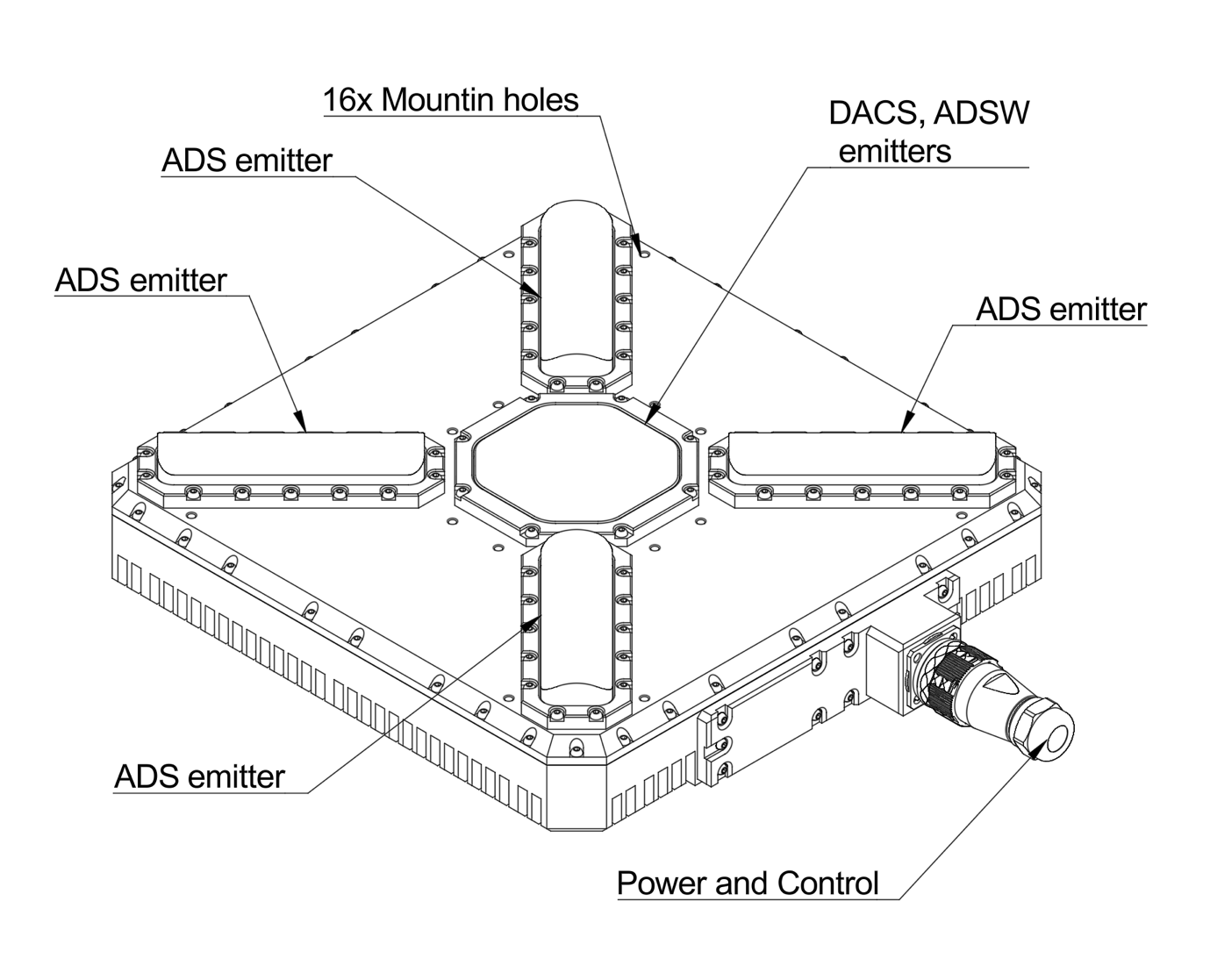
Figure: ULS-Heli-G2 Transmitter A transmitter is a device placed on the ground (platform, moving object). It emits a signal in the Infrared range and serves as a kind of beacon. Transmitter marks position for drone landing. The primary function of the transmitter is to continuously send out a coded signal that can be detected and interpreted by the receiver unit onboard the XCopter. This signal contains critical information needed for the operation of the system, such as positional data, commands, and status.
Receiver (Onboard Unit)
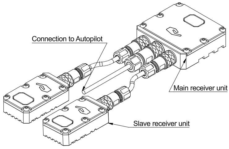
Figure: ULS-Heli-G2 Receiver A receiver is a device that is placed on board an aircraft. The receiver decodes this signal to derive flight information such as positional coordinates, real-time transmitter status updates, and landing guidance. It interprets the data to navigate accurately and ensure drone follows the intended flight path. It provides feedback to the autopilot systems, such as Ardupilot and PX4, to adjust the flight parameters as needed for optimal and safety landing or hovering above.
Part Numbering
| Part Number | Description |
|---|---|
| ULS-HELI-G2 | System set with 3 receivers. |
| ULSDV-HL-TX-G2 | Transmitter unit. |
| ULSDV-HL-RXM-G2 | Master receiver unit. |
| ULSDV-HL-RXS-G2 | Slave receiver unit. |
| SA610/P4IB | 4 Pin Connector for receiver. Manufacturer Weipu. |
| SA810/P8IIB | 8 Pin Connector for receiver. Manufacturer Weipu. |
| SA1610/P10IIB-1 | 10 Pin Connector for transmitter. Manufacturer Weipu. |
Table: Part Numbering
System specification.
| Parameter | Value |
|---|---|
| Distance range m.: | 50.0 |
| Working angle (deg): | 60 |
| Data update frequency (Hz): | 20 |
Table: Common Specification
| Parameter | Value |
|---|---|
| Field of view (deg): | 90 |
| Dimensions mm : | 46x26x12 |
| Weight g.: | 40 |
| Power Consumption (W): | 3 |
| Voltage supply (V): | 5 |
| Interfaces: | USB, CAN, UART |
Table: Receiver (Slave) Specifications
| Parameter | Value |
|---|---|
| Field of view (deg): | 90 |
| Dimensions mm : | 50x50x14 |
| Weight g. : | 60 |
| Power Consumption (W): | 3 |
| Voltage supply (V): | 5 |
| Interfaces: | USB, CAN, UART |
Table: Receiver (Master) Specifications
| Parameter | Value |
|---|---|
| Field of emitting (deg): | 60 |
| Dimensions mm. : | 290x215x48 |
| Weight g.: | 4100 |
| Power Consumption (W): | 10 |
| Voltage supply (V): | 22.0-26.0 |
| Interfaces : | USB, CAN, UART |
Table: Transmitter (Ground) Specifications
Pinout Information
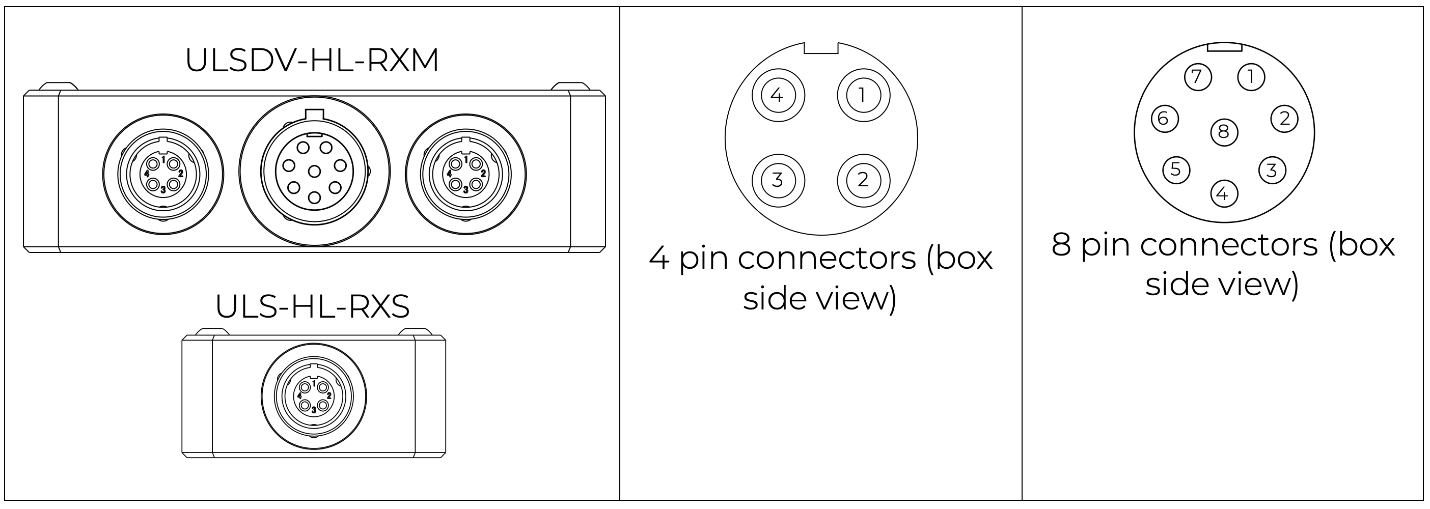
| Pin | Function |
|---|---|
| 1 | Vin (+5V) |
| 2 | CANH |
| 3 | CANL |
| 4 | GND |
Table: 4 Pin Connector Pinout
| Pin | Function |
|---|---|
| 1 | Vin (+5V) |
| 2 | CANH |
| 3 | CANL |
| 4 | UART_TX (OUT) |
| 5 | UART_RX(IN) |
| 6 | USB_D- |
| 7 | USB_D+ |
| 8 | GND |
Table: 8 Pin Connector Pinout
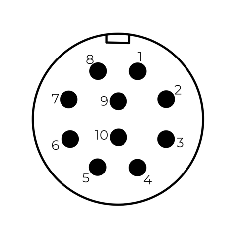
| Pin | Function |
|---|---|
| 1 | Vin +18V – +28V |
| 2 | RS422A |
| 3 | RS422B |
| 4 | RS422Y |
| 5 | RS422Z |
| 6 | CAN-L |
| 7 | CAN-H |
| 8 | USB-D- |
| 9 | USB-D+ |
| 10 | GND |
Table: Transmitter 10 Pin Connector Pinout
Please DO NOT "HOT-PLUG" Transmitter cable. Apply power on transmitter only when connector connected to transmitter.
Please check pin numbers on connector.
Incorrect wiring or connection under voltage can damage the device and USB interface of connected PC !
Mechanical dimensions
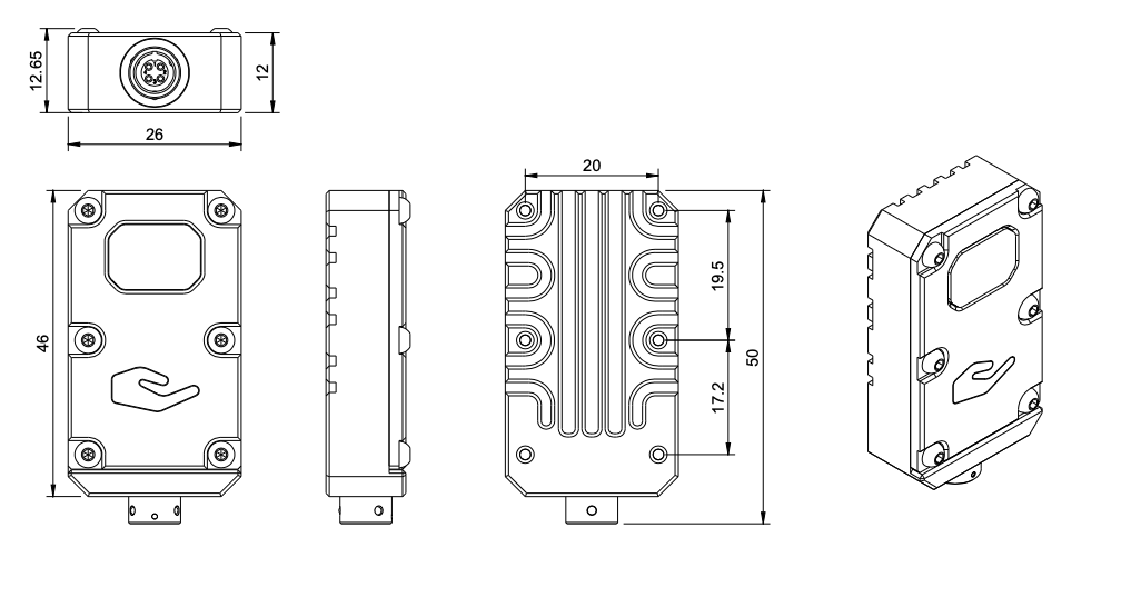
Figure: Slave receiver Mechanical Dimensions
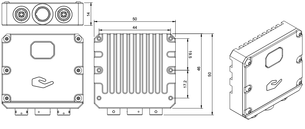
Figure: Master receiver Mechanical Dimensions
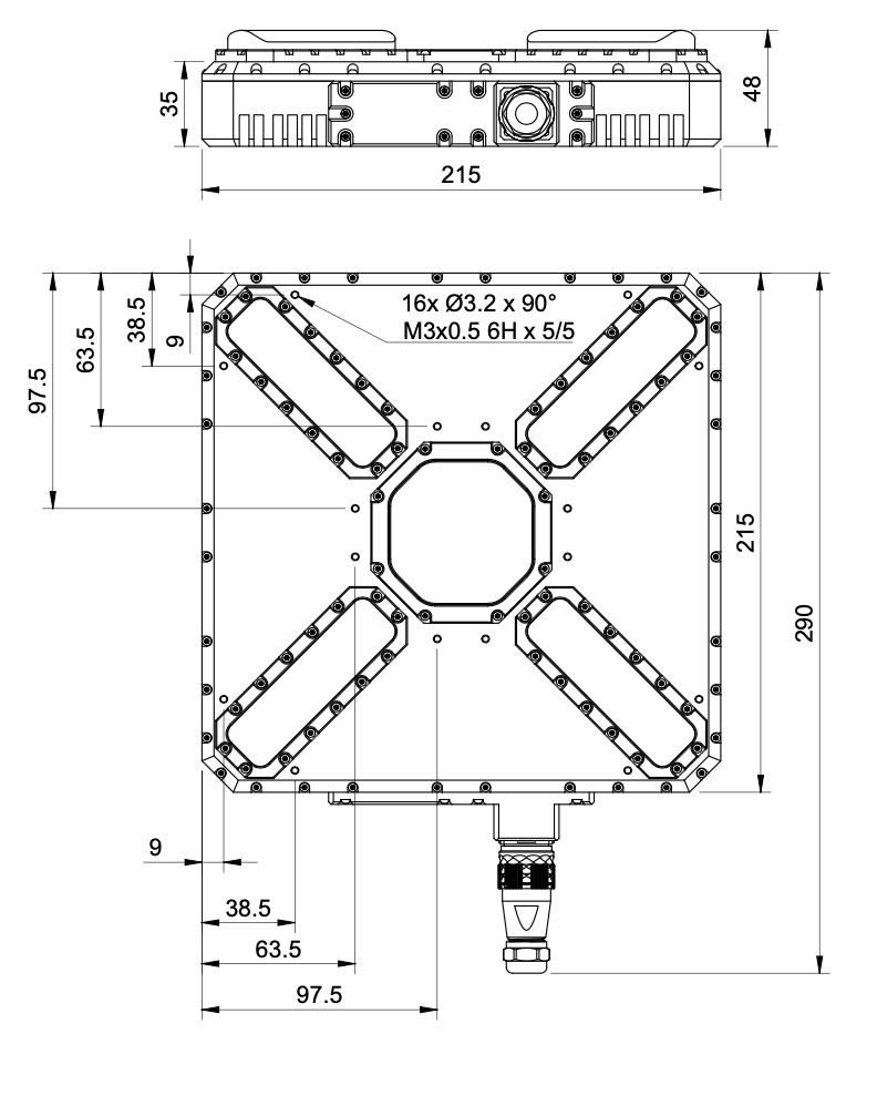
Figure: Transmitter Mechanical Dimensions
Packaging information
The device is shipped in a protective case.
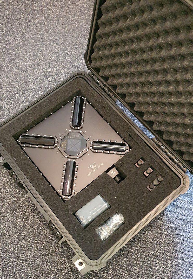
Figure: Protective Packaging Case
Environmental Conditions
Environmental Conditions - Industrial Grade
Equipment is designed to operate reliably in demanding environmental conditions typical of aerospace, industrial automation, and outdoor applications.
Operating Temperature Range
- Standard operating range: -20°C to +55°C
- Covers most industrial and outdoor applications
- Reliable performance across temperature extremes
- No performance degradation within specified range
Humidity Tolerance
- Relative humidity: Up to 70% (non-condensing)
- Protected against moisture in typical operating conditions
- Suitable for outdoor and semi-protected installations
- Condensation prevention through sealed design
Ingress Protection
- IP67 rated (Dust tight and water immersion resistant)
- 6 - Complete protection against dust ingress
- 7 - Protected against temporary immersion in water (up to 1 meter depth for 30 minutes)
- Suitable for harsh industrial environments
- Protected against rain, splashing, and temporary submersion
- Dust-tight sealing for contaminated environments
Storage Conditions
- Storage temperature: -40°C to +70°C
- Relative humidity: Up to 95% (non-condensing)
- Long-term storage in industrial facilities
Operational Environment Standards
- Designed to meet industrial equipment requirements
- Suitable for UAV/drone applications
- Outdoor installation capable
- Protected against:
- Dust and particulate matter
- Water spray and rain
- Temporary water immersion
- Temperature fluctuations
- High humidity
Change Control
All changes to this document must be reviewed and approved by the relevant technical leads and stakeholders
6.2 - ULS-Heli-G2 Interface Control Document
Interface Control Document ULSDC-PBICD210925, version 1.0.1
ULSDC-PBICD210925 · version 1.0.1 · issued September 22, 2025
The numbered PDF is the controlled copy: download it from the portal.
Introduction
Purpose
This document outlines the interfaces between the ULS-Heli-G2 system components, including the transmitter, receiver, and autopilot systems (Ardupilot and PX4 and similar).
Scope
This document is intended for use by system engineers, integrators, and developers working with ULS-Heli-G2 systems. It provides detailed information on the interfaces between the system components, ensuring seamless integration and operation.
System Components
Transmitter (Ground Unit)
Figure: ULS-Heli-G2 Transmitter A transmitter is a device placed on the ground (platform, moving object). It emits a signal in the Infrared range and serves as a kind of beacon. Transmitter marks position for drone landing. The primary function of the transmitter is to continuously send out a coded signal that can be detected and interpreted by the receiver unit onboard the XCopter. This signal contains critical information needed for the operation of the system, such as positional data, commands, and status.
Receiver (Onboard Unit)
Figure: ULS-Heli-G2 Receiver A receiver is a device that is placed on board an aircraft. The receiver decodes this signal to derive flight information such as positional coordinates, real-time transmitter status updates, and landing guidance. It interprets the data to navigate accurately and ensure drone follows the intended flight path. It provides feedback to the autopilot systems, such as Ardupilot and PX4, to adjust the flight parameters as needed for optimal and safety landing or hovering above.
Interface Overview
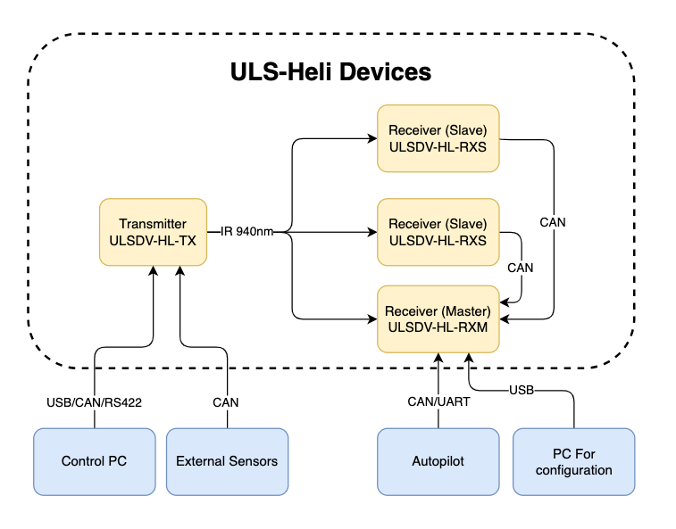
Figure: ULS-Heli-G2 System Interfaces Overview
Transmitter to Control PC Interface (External Sensors)
The transmitter can be connected to a control PC or external equipment for configuration, status monitoring, and data exchange.
Data Types
- Status information
- Control signals
- Transmitter configuration
- External IMU/COMPASS data
Connection Types
- CAN Bus - For network communication
- USB - For configuration and firmware updates
- RS422 - For serial communication with external sensors
Transmitter Pinout
| Pin | Function |
|---|---|
| 1 | Vin +18V – +28V |
| 2 | RS422A |
| 3 | RS422B |
| 4 | RS422Y |
| 5 | RS422Z |
| 6 | CAN-L |
| 7 | CAN-H |
| 8 | USB-D- |
| 9 | USB-D+ |
| 10 | GND |
Table: Transmitter 10 Pin Connector Pinout
Please DO NOT "HOT-PLUG" Transmitter cable. Apply power on transmitter only when connector connected to transmitter.
Please check pin numbers on connector.
Incorrect wiring or connection under voltage can damage the device and USB interface of connected PC !
Transmitter to Receiver Interface
The transmitter and receiver use an optical interface to exchange data. Transmission uses IR emission at 940 nanometers. Data transmission is only in the direction from the transmitter to the receiver.
Data Types
- Position encoded
- Status encoded data (Transmitter orientation and instructions)
Connection Type
- Optical IR 940nm - Infrared optical link
Receiver to Autopilot and Receiver to PC Interfaces
Data Types
- MAVLink messages
- ULS-Blitz frames
- ASCII protocol
Connection Types
- UART - Serial communication with autopilot
- CAN - Network communication
- USB - Direct PC connection
Receiver Pinout
| Pin | Function |
|---|---|
| 1 | Vin (+5V) |
| 2 | CANH |
| 3 | CANL |
| 4 | GND |
Table: 4 Pin Connector Pinout
| Pin | Function |
|---|---|
| 1 | Vin (+5V) |
| 2 | CANH |
| 3 | CANL |
| 4 | UART_TX (OUT) |
| 5 | UART_RX(IN) |
| 6 | USB_D- |
| 7 | USB_D+ |
| 8 | GND |
Table: 8 Pin Connector Pinout
Powering Interfaces
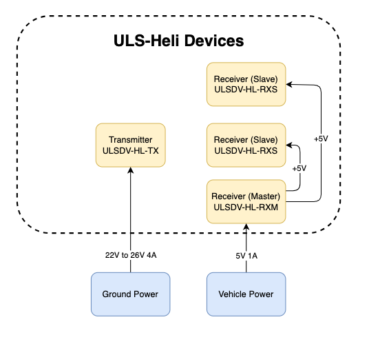
Figure: Power Distribution and Connections
Transmitter Electrical Characteristics
| Parameter | Value | Unit | Notes |
|---|---|---|---|
| Supply Voltage | 22.0 - 26.0 | V | Nominal 24V |
| Supply Current | 4 | A | Peak |
| Power Consumption | 18.1 | W | Typical |
Table: Transmitter Electrical Specifications
Receiver Electrical Characteristics
| Parameter | Value | Unit | Notes |
|---|---|---|---|
| Supply Voltage | 5.0 | V | From flight controller |
| Supply Current | 1 | A | Peak |
| Power Consumption | 3 | W | Typical |
Table: Receiver Electrical Specifications
Functional Interfaces
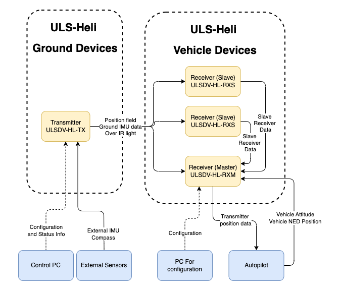
Figure: Data Flow and Functional Interfaces
Data Exchange
The ULS-Heli-G2 system implements several data exchange mechanisms:
Control PC Functions:
- Configure and view status of transmitter
- Set configuration of receivers
- Send control signals (On/off, compass override information)
External Equipment:
- External IMU/Compass equipment can be used to override internal IMU/compass information
Receiver Functions:
- Accept data from transmitter over IR signal (position field information and ground unit IMU data)
- Accept NED and Attitude information from autopilot to convert coordinate system
- Multiple receivers can communicate to calculate vehicle orientation (YAW)
- Send position offset data to autopilot
Mechanical Interfaces
Figure: Slave receiver Mechanical Dimensions
Figure: Master receiver Mechanical Dimensions
Figure: Transmitter Mechanical Dimensions
Transmitter Mounting
Use 16 mounting holes to mount transmitter to panel. 3D model of the transmitter can be provided upon request.
Receiver Mounting
Both master and slave receivers have mounting provisions for secure installation. 3D models of the receivers can be provided upon request.
Communication Protocols
Overview
The protocol used by devices for configuration is proprietary and is described in other documents. However, the protocol implements the possibility of transmitting messages (Blitz messages) that can be used by the user to control the device and obtain information. These messages are universal, and the format describes the data that is transmitted by various devices in our system connected to a single network.
Use CMD=6 to send Blitz messages.
In this document, the CAN protocol is specified. RS485 is used to implement custom protocols that can be defined in the future.
CAN Bus Protocol Frame Format
flowchart LR
  A[Sender Device] --> B[GLOBAL]
  B --> C[CMD = 6]
  C --> D[ID]
  D --> E[dsn_lid]
  E --> F[msg_id]
  F --> G[Blitz Payload data <= 8 bytes]
  G --> H[Receiver Device]
The CAN protocol uses the following frame structure:
| Field | Description |
|---|---|
| GLOBAL | Flag used to send packets over several local networks |
| CMD | Command field (Use CMD=6 to send Blitz messages) |
| ID | Packet sender ID (local id src_lid for local packets and device id for global packets src_did) |
| dsn_lid | Destination local ID address |
| msg_id | Message ID used to identify Blitz packet types |
Table: CAN Protocol Frame Fields
Status Bit Definitions
Most messages include a status byte with the following bit definitions:
| Bit | Flag | Description |
|---|---|---|
| 0 | ULS_STATUS_RX_CARRIER_OK | IR signal detected |
| 1 | ULS_STATUS_RX_SQ_OK | Signal quality OK |
| 2 | ULS_STATUS_RX_POS_OK | Position estimated |
| 3 | ULS_STATUS_RX_VEL_OK | Velocity estimated |
| 4 | ULS_STATUS_RX_GU_IMU_OK | Ground Unit IMU OK |
| 5 | ULS_STATUS_RX_MRX_OK | MRX message received (secondary receiver) |
| 6 | ULS_STATUS_RX_MRXDATA_OK | MRX Yaw and Distance calculated OK |
Table: Status Bit Definitions
Common Data Structure
Blitz Common Data Structure
Structure: __blitz_common_data_struct
| Field | Type | Description |
|---|---|---|
src_lid | uint8_t | Source logical ID |
msg_id | uint16_t | Message ID (see message types below) |
data | union | Message-specific data (8 bytes max) |
Table: Blitz Common Data Structure The union contains all possible message structures:
xcg1_rx_raw_measurmetrx_raw_measurmetrx_pos_in_tx_framerx_mrxrx_dacs
Usage: Universal container for all ULS Blitz message types.
Implementation Notes
- Packed Structures: All structures use
__attribute__((packed))to ensure no padding bytes are added by the compiler. - Endianness: The protocol assumes little-endian byte order for multi-byte fields.
- Angular Precision: Angular measurements use 16-bit signed integers with specific scaling factors for different ranges.
- Distance Units: Distance measurements may use different units (cm, 10cm increments) depending on the message type.
Message Types
XCG1 Raw Measurement (0x0010)
Message ID: ULS_BLITZ_MSG_ID_XCG1_RX_RAW_MEASURMENT (0x0010)
Structure: __uls_blitz_xcg1_rx_raw_measurmet
| Field | Type | Description |
|---|---|---|
status | uint8_t | Status bits (see Status Bit Definitions above) |
d | uint8_t | Distance in 10 cm increments |
aX | int16_t | Angular information X-axis, proportional [-30000 = -30°, +30000 = +30°] |
aY | int16_t | Angular information Y-axis, proportional [-30000 = -30°, +30000 = +30°] |
oF | int8_t | Sensor offset Forward in cm |
oR | int8_t | Sensor offset Right in cm |
Table: XCG1 Raw Measurement Message Format Purpose: Legacy raw measurement data for XCG1 systems with limited angular range.
Raw Measurement (0x0011)
Message ID: ULS_BLITZ_MSG_ID_RX_RAW_MEASURMENT (0x0011)
Structure: __uls_blitz_msg_rx_raw_measurmet
| Field | Type | Description |
|---|---|---|
status | uint8_t | Status bits (see Status Bit Definitions above) |
counter | uint8_t | Message counter for tracking |
aX | int16_t | Angular information X-axis [-180° to +180°] |
aY | int16_t | Angular information Y-axis [-180° to +180°] |
distance | uint16_t | Distance measurement |
Table: Raw Measurement Message Format Angular Conversion Formula:
degrees = (value_int16 * 180.0f) / 32767.0f
Purpose: Standard raw measurement data with full angular range.
Position in TX Frame (0x0012)
Message ID: ULS_BLITZ_MSG_ID_RX_POS_IN_TX_FRAME (0x0012)
Structure: __uls_blitz_msg_rx_pos_in_tx_frame
| Field | Type | Description |
|---|---|---|
status | uint8_t | Status bits (see Status Bit Definitions above) |
counter | uint8_t | Message counter for tracking |
posX | int16_t | Position X-coordinate in transmitter frame (cm) |
posY | int16_t | Position Y-coordinate in transmitter frame (cm) |
posZ | int16_t | Position Z-coordinate in transmitter frame (cm) |
Table: Position in TX Frame Message Format Purpose: 3D position data relative to the transmitter coordinate system.
MRX Information (0x0013)
Message ID: ULS_BLITZ_MSG_ID_RX_MRX (0x0013)
Structure: __uls_blitz_msg_rx_mrx
| Field | Type | Description |
|---|---|---|
status | uint8_t | Status bits (see Status Bit Definitions above) |
counter | uint8_t | Message counter for tracking |
yaw | int16_t | Yaw angle [-180° to +180°] |
distance | uint16_t | Distance measurement in cm |
Table: MRX Information Message Format Purpose: Multi-receiver (MRX) information for secondary receiver data.
DACS Information (0x0014)
Message ID: ULS_BLITZ_MSG_ID_RX_DACS (0x0014)
Structure: __uls_blitz_msg_rx_dacs
| Field | Type | Description |
|---|---|---|
status | uint8_t | Status bits (see Status Bit Definitions above) |
counter | uint8_t | Message counter for tracking |
yaw | int16_t | Yaw angle [-180° to +180°] |
distance | uint16_t | Distance measurement |
yawContinuous | int16_t | Continuous yaw angle ±32768° |
Table: DACS Information Message Format Purpose: DACS (Distance and Azimuth Correction System) data with continuous yaw tracking. Available on VTOL systems only.
Ground IMU Measurement (0x0020)
Message ID: ULS_BLITZ_MSG_ID_GIMU_MEASUREMENT (0x0020)
Structure: __uls_blitz_msg_gimu_data
| Field | Type | Description |
|---|---|---|
status | uint8_t | Status bits (see Status Bit Definitions above) |
counter | uint8_t | Message counter for tracking |
roll | int16_t | Roll angle [-180° to +180°] |
pitch | int16_t | Pitch angle [-180° to +180°] |
yaw | int16_t | Yaw angle [-180° to +180°] |
Table: Ground IMU Measurement Message Format Angular Conversion Formula:
degrees = (value_int16 * 180.0f) / 32767.0f
Purpose: Ground unit IMU (Inertial Measurement Unit) orientation data.
IMU Override (0x0030)
Message ID: ULS_BLITZ_MSG_ID_XX_TXC_IMU_OVERRIDE (0x0030)
Structure: __uls_blitz_msg_xx_txc_imu_override
| Field | Type | Description |
|---|---|---|
control | uint8_t | Control bits (see Control Bits below) |
counter | uint8_t | Message counter for tracking |
roll | int16_t | Override roll angle [-180° to +180°] |
pitch | int16_t | Override pitch angle [-180° to +180°] |
yaw | int16_t | Override yaw angle [-180° to +180°] |
Table: IMU Override Message Format Control Bits:
| Bit | Description |
|---|---|
| 0 | SET Roll - Enable roll angle override |
| 1 | SET Pitch - Enable pitch angle override |
| 2 | SET Yaw - Enable yaw angle override |
| 3-7 | Reserved |
Table: IMU Override Control Bits Angular Conversion Formula:
degrees = (value_int16 * 180.0f) / 32767.0f
Purpose: Override IMU data on ground unit for external orientation control.
Magnetometer Override (0x0031)
Message ID: ULS_BLITZ_MSG_ID_XX_TXC_MAG_OVERRIDE (0x0031)
Structure: __uls_blitz_msg_xx_txc_mag_override
| Field | Type | Description |
|---|---|---|
control | uint8_t | Control bits (see Control Bits below) |
counter | uint8_t | Message counter for tracking |
mx | int16_t | Magnetic field X-component |
my | int16_t | Magnetic field Y-component |
mz | int16_t | Magnetic field Z-component |
Table: Magnetometer Override Message Format Control Bits:
| Bit | Description |
|---|---|
| 0 | SET override - Enable magnetometer override |
| 1-7 | Reserved |
Table: Magnetometer Override Control Bits Magnetic Field Conversion Formula:
mag_value = (value_int16 * 1.0f) / 32767.0f
Purpose: Override magnetometer data on ground unit for external compass control.
Environmental Conditions
For the Receiver Unit
- Operating temperature range: -40°C to +85°C
- Humidity range: Less than 70%
- Dust and moisture protection: IP67
- 6 - Complete protection against dust ingress
- 7 - Protected against temporary immersion in water (up to 1 meter depth for 30 minutes)
For the Transmitter Unit
- Operating temperature range: -40°C to +85°C
- Humidity range: Less than 70%
- Dust and moisture protection: IP67
- 6 - Complete protection against dust ingress
- 7 - Protected against temporary immersion in water (up to 1 meter depth for 30 minutes)
Storage Conditions
- Storage temperature: -40°C to +85°C
- Relative humidity: Up to 70% (non-condensing)
- The receiver unit does not requires additional protective measures in dusty or moist environments
- The transmitter unit can operate in harsh outdoor conditions without additional protection
- Extended temperature range (-40°C to +85°C) enables operation in extreme climates
Part Numbering
| Part Number | Description |
|---|---|
| ULS-HELI-G2 | System set with 3 receivers. |
| ULSDV-HL-TX-G2 | Transmitter unit. |
| ULSDV-HL-RXM-G2 | Master receiver unit. |
| ULSDV-HL-RXS-G2 | Slave receiver unit. |
| SA610/P4IB | 4 Pin Connector for receiver. Manufacturer Weipu. |
| SA810/P8IIB | 8 Pin Connector for receiver. Manufacturer Weipu. |
| SA1610/P10IIB-1 | 10 Pin Connector for transmitter. Manufacturer Weipu. |
Table: Part Numbering
Specifications
| Parameter | Value |
|---|---|
| Distance range m.: | 50.0 |
| Working angle (deg): | 60 |
| Data update frequency (Hz): | 20 |
Table: Common Specification
| Parameter | Value |
|---|---|
| Field of view (deg): | 90 |
| Dimensions mm : | 46x26x12 |
| Weight g.: | 40 |
| Power Consumption (W): | 3 |
| Voltage supply (V): | 5 |
| Interfaces: | USB, CAN, UART |
Table: Receiver (Slave) Specifications
| Parameter | Value |
|---|---|
| Field of view (deg): | 90 |
| Dimensions mm : | 50x50x14 |
| Weight g. : | 60 |
| Power Consumption (W): | 3 |
| Voltage supply (V): | 5 |
| Interfaces: | USB, CAN, UART |
Table: Receiver (Master) Specifications
| Parameter | Value |
|---|---|
| Field of emitting (deg): | 60 |
| Dimensions mm. : | 290x215x48 |
| Weight g.: | 4100 |
| Power Consumption (W): | 10 |
| Voltage supply (V): | 22.0-26.0 |
| Interfaces : | USB, CAN, UART |
Table: Transmitter (Ground) Specifications
Change Control
All changes to this document must be reviewed and approved by the relevant technical leads and stakeholders
6.3 - ULS-Heli-G2 Operation Manual
Operation Manual ULSDC-PBOM210925, version 1.0.0
ULSDC-PBOM210925 · version 1.0.0 · issued January 26, 2026
The numbered PDF is the controlled copy: download it from the portal.
ULS-Heli-G2 Operation Manual
Table of Contents
- Introduction
- Safety Information
- Getting Started
- Installation
- Basic Operation
- Advanced Features
- Troubleshooting
- Maintenance
- Specifications
- Support
Introduction
Purpose
The ULS-Heli-G2 is a professional-grade optical positioning system designed to enable precision approach and landing for helicopters and heavy-lift rotary-wing UAVs. It provides reliable short-range positioning in GPS-denied or degraded environments, including maritime and industrial operations.
Scope
This manual covers safe operation, installation, configuration, and routine maintenance of the ULS-Heli-G2 system, including aircraft receivers (Master/Slave) and the ground transmitter (Beacon).
Intended Audience
Pilots, flight technicians, and integration engineers responsible for installing and operating the system on helicopters or heavy-lift rotary UAV platforms.
Safety Information
Important Safety Guidelines
- WARNING: Rotary-wing aircraft operations are inherently hazardous. Only qualified personnel should install and operate this system.
- WARNING: Avoid direct eye exposure to high-intensity optical emitters. Do not stare into the Beacon emission aperture.
- CAUTION: Ensure secure mounting and vibration isolation compliant with airworthiness requirements for your platform.
- CAUTION: Verify electromagnetic compatibility and power budgets when integrating with aircraft systems.
- NOTE: Maintain clear line-of-sight between aircraft receivers and ground Beacon during approach and landing.
Regulatory Compliance
- System components should be installed per applicable aviation regulations and local maritime/industrial standards.
- Environmental considerations: the system is qualified for all-weather operation; verify local restrictions for optical emissions.
Getting Started
What’s in the Box
- 1× Ground Transmitter (Beacon) — heavy-duty IP-rated enclosure
- 1× Master Receiver — aircraft unit with enhanced features
- 2× Slave Receivers — compact aircraft units for redundancy
- Connection cables — USB, CAN, UART interface options
- Mounting hardware — aircraft and ground mounting kits
- Documentation — datasheet and operation manual
System Requirements
- Aircraft power for receivers: 5 V DC, ~3 W per receiver
- Ground power for Beacon: 22–26 V DC, ~10 W
- Supported autopilots: ArduPilot Helicopter (native), PX4 compatible; or custom AP via USB/UART/CAN
- Clear approach corridor ensuring line-of-sight to Beacon
Installation
1. Preparation
- Review aircraft electrical and mechanical integration constraints (space, power, EMI/EMC).
- Identify mounting locations for receivers with unobstructed forward field of view (~90°).
- Select Beacon site providing 60° emission coverage and safe standoff from rotor/obstacles.
2. Ground Transmitter (Beacon) Mounting
- Mount the Beacon on a stable platform (deck/helipad) within the planned landing area.
- Ensure emission aperture faces the approach path; verify no occlusion within 60° working angle.
- Connect 22–26 V DC supply; confirm IP-rated sealing and strain relief on cables.
3. Aircraft Receiver Installation
- Install Master and Slave receivers per platform layout, oriented to maximize forward line-of-sight.
- Provide vibration isolation per aircraft standards; route cables securely away from moving parts.
- Connect power (5 V DC) and chosen data interface (USB, UART, or CAN) to the flight computer/AP.
4. Initial Setup
- Power Beacon and receivers; confirm device enumerations and link status on AP.
- Configure AP integration (ArduPilot/PX4) to accept ULS-Heli-G2 positioning input.
- Perform alignment check: validate that receiver FOVs cover the approach corridor; adjust mounts if needed.
Basic Operation
Power-On Sequence
- Power Beacon and verify status indicator.
- Power aircraft receivers; confirm data link availability.
- Verify AP integration: positioning data visible and updating at 20 Hz.
Approach and Landing
- Establish approach with direct line-of-sight to Beacon within 50 m range.
- Maintain alignment within the 60° working angle.
- Monitor horizontal/vertical offsets on AP/HMI; use cues to correct approach.
- Execute landing per SOPs; system supports <5 cm horizontal and <10 cm vertical accuracy at 1 m (linearly scaling).
Operating Notes
- System operates day/night and in adverse weather (rain, fog, snow, dust) within qualified limits.
- If dual receivers are installed, Master manages fusion and automatic failover.
Advanced Features
Dual Receiver Configuration (Master/Slave)
- Redundancy with automatic failover for critical operations.
- Cross-checking and sensor fusion for enhanced accuracy.
- Independent power supplies recommended.
Interfaces
- USB, UART, CAN for integration to flight computers or custom APs.
- ArduPilot Helicopter: native support; PX4: full compatibility.
Update Rate and FOV
- 20 Hz update rate for smooth positioning.
- Receiver FOV ~90°; Beacon emission angle ~60°.
Troubleshooting
| Problem | Possible Cause | Solution |
|---|---|---|
| No positioning data | Interface misconfiguration | Verify AP settings; check USB/UART/CAN wiring |
| Intermittent updates | Obstructed line-of-sight or FOV misalignment | Re-orient receivers/Beacon; clear approach corridor |
| Reduced accuracy | Excessive vibration or misalignment | Improve mounting isolation; re-check alignment |
| Beacon not powering | Supply out of range | Verify 22–26 V DC and cable integrity |
| Receiver not powering | 5 V supply issue | Check aircraft power rail and connectors |
Maintenance
Regular Maintenance
- Clean receiver optics and Beacon aperture; remove salt spray/dust.
- Inspect mounts, fasteners, and cable strain relief.
- Verify firmware/software compatibility with AP after updates.
Preventive Maintenance
- Quarterly alignment verification and functional tests.
- Replace worn vibration isolators per aircraft maintenance schedule.
Specifications
System Performance
- Horizontal Accuracy: <5 cm at 1 m (linear scaling)
- Vertical Accuracy: <10 cm
- Operating Range: up to 50 m
- Update Rate: 20 Hz
- Working Angle (Beacon): 60°
Receiver (Slave)
- Weight: 40 g
- Dimensions: 46 × 26 × 12 mm
- Field of View: 90°
- Power Consumption: 3 W
- Supply Voltage: 5 V DC
- Interfaces: USB, CAN, UART
Receiver (Master)
- Weight: 60 g
- Dimensions: 50 × 50 × 14 mm
- Field of View: 90°
- Power Consumption: 3 W
- Supply Voltage: 5 V DC
- Interfaces: USB, CAN, UART
Beacon (Ground)
- Weight: 4100 g
- Dimensions: 290 × 215 × 48 mm
- Emission Angle: 60°
- Power Consumption: 10 W
- Supply Voltage: 22–26 V DC
- Interfaces: USB, CAN, UART
Support
- Technical Support and Services available via the website contact page.
- For integration assistance (ArduPilot/PX4/custom AP), engage engineering support.
6.4 - ULS-Heli-G2 Precision Landing System
Document ULSDC-PBFL210925-L, version 1.0.0
ULSDC-PBFL210925-L · version 1.0.0 · issued 2025-11-10
The numbered PDF is the controlled copy: download it from the portal.
ULS-Heli-G2 Precision Landing System
Infrared-Based UAV Autonomous Landing Solution | 50m Range | IP67 | -20°C to +55°C
Why Choose ULS-Heli-G2?
✓ 50m Operating Range | ✓ Work in GNSS denied environment | ✓ No Radio Connection required | ✓ 20Hz Update Rate | ✓ Plug & Play Integration| ✓ IP67 Protection
Precision landing technology for UAVs requiring accurate positioning and safe autonomous landing on stationary or moving platforms. The ULS-Heli-G2 system enables precise autonomous UAV landing through infrared positioning technology. The system consists of a ground-based transmitter that emits coded infrared signals, and onboard receivers that calculate real-time position and orientation data.
How It Works
- Ground Transmitter (TX) - Infrared beacon continuously emits coded positioning signals in a 60° cone
- Onboard Receivers (RX) - Master + 2 Slave units mounted on UAV decode signals and calculate 6DOF position (X, Y, Z, Roll, Pitch, Yaw)
System Components
| Component | Size (mm) | Weight | FOV/Angle | Power | Details |
|---|---|---|---|---|---|
| Transmitter | 290×215×48 | 4100g | 60° emit | 10W, 22-26V | Ground beacon with omnidirectional mounting |
| Master RX | 50×50×14 | 60g | 90° | 3W, 5V | Primary receiver with data processing |
| Slave RX | 46×26×12 | 40g | 90° | 3W, 5V | Secondary receivers for triangulation |
Communication: USB, CAN, UART (115200 baud) | Autopilot Support: Ardupilot, PX4, Custom integration
Data Output: Position (X/Y/Z), Orientation (Roll/Pitch/Yaw), Signal quality, System status
Technical Specifications
Performance
| Feature | Value | Notes |
|---|---|---|
| Operating Range | Up to 50m | Optimal performance 0.3-40m |
| Update Rate | 20Hz | Real-time position updates |
| Accuracy | ±5cm @ 10m | Varies with distance and conditions |
| Latency | <50ms | End-to-end signal processing |
| Transmitter Angle | 60° cone | Covers landing zone |
| Receiver FOV | 90° per unit | Wide field of view for approach |
| Operating Temp | -20°C to +55°C | Industrial grade components |
| Storage Temp | -40°C to +70°C | Extended range for transport |
| Protection Rating | IP67 | Dust-tight, water immersion protected |
| Humidity | <70% RH | Non-condensing conditions |
Applications & Use Cases
Primary Applications
🚁 UAV Autonomous Landing - Precise landing on stationary or moving platforms with real-time position feedback
🚢 Marine Operations - Ship deck landing systems for maritime surveillance and logistics
⚡ Emergency Services - Reliable landing assistance in challenging conditions and low-visibility environments
Key Benefits
- All-Weather Operation - IR technology unaffected by lighting conditions, works day and night
- Moving Platform Capability - Real-time 6DOF tracking enables landing on ships, vehicles, or dynamic surfaces
- No GPS Required - Operates in GPS-denied environments (indoors, urban canyons)
- Plug & Play Integration - Compatible with major autopilot systems, minimal configuration
Contact Us
UAVLAS sp. z o.o. | 📧 info@uavlas.com | 🌐 www.uavlas.com |
ULS-Heli-G2 - Precision Landing Made Simple
6.5 - ULS-Heli-G2 Precision Landing System
Document ULSDC-PBFL210925, version 1.0.0
ULSDC-PBFL210925 · version 1.0.0 · issued 2025-11-10
The numbered PDF is the controlled copy: download it from the portal.
ULS-Heli-G2 Precision Landing System
Infrared-Based UAV Autonomous Landing Solution | 50m Range | IP67 | -20°C to +55°C
Why Choose ULS-Heli-G2?
✓ 50m Operating Range | ✓ Work in GNSS denied environment | ✓ No Radio Connection required | ✓ 20Hz Update Rate | ✓ Plug & Play Integration| ✓ IP67 Protection
Precision landing technology for UAVs requiring accurate positioning and safe autonomous landing on stationary or moving platforms. The ULS-Heli-G2 system enables precise autonomous UAV landing through infrared positioning technology. The system consists of a ground-based transmitter that emits coded infrared signals, and onboard receivers that calculate real-time position and orientation data.
How It Works
- Ground Transmitter (TX) - Infrared beacon continuously emits coded positioning signals in a 60° cone
- Onboard Receivers (RX) - Master + 2 Slave units mounted on UAV decode signals and calculate 6DOF position (X, Y, Z, Roll, Pitch, Yaw)
System Components
| Component | Size (mm) | Weight | FOV/Angle | Power | Details |
|---|---|---|---|---|---|
| Transmitter | 290×215×48 | 4100g | 60° emit | 10W, 22-26V | Ground beacon with omnidirectional mounting |
| Master RX | 50×50×14 | 60g | 90° | 3W, 5V | Primary receiver with data processing |
| Slave RX | 46×26×12 | 40g | 90° | 3W, 5V | Secondary receivers for triangulation |
Communication: USB, CAN, UART (115200 baud) | Autopilot Support: Ardupilot, PX4, Custom integration
Data Output: Position (X/Y/Z), Orientation (Roll/Pitch/Yaw), Signal quality, System status
Technical Specifications
Performance
| Feature | Value | Notes |
|---|---|---|
| Operating Range | Up to 50m | Optimal performance 0.3-40m |
| Update Rate | 20Hz | Real-time position updates |
| Accuracy | ±5cm @ 10m | Varies with distance and conditions |
| Latency | <50ms | End-to-end signal processing |
| Transmitter Angle | 60° cone | Covers landing zone |
| Receiver FOV | 90° per unit | Wide field of view for approach |
| Operating Temp | -20°C to +55°C | Industrial grade components |
| Storage Temp | -40°C to +70°C | Extended range for transport |
| Protection Rating | IP67 | Dust-tight, water immersion protected |
| Humidity | <70% RH | Non-condensing conditions |
Applications & Use Cases
Primary Applications
🚁 UAV Autonomous Landing - Precise landing on stationary or moving platforms with real-time position feedback
🚢 Marine Operations - Ship deck landing systems for maritime surveillance and logistics
⚡ Emergency Services - Reliable landing assistance in challenging conditions and low-visibility environments
Key Benefits
- All-Weather Operation - IR technology unaffected by lighting conditions, works day and night
- Moving Platform Capability - Real-time 6DOF tracking enables landing on ships, vehicles, or dynamic surfaces
- No GPS Required - Operates in GPS-denied environments (indoors, urban canyons)
- Plug & Play Integration - Compatible with major autopilot systems, minimal configuration
Contact Us
UAVLAS sp. z o.o. | 📧 info@uavlas.com | 🌐 www.uavlas.com |
ULS-Heli-G2 - Precision Landing Made Simple
7 - ULS-Heli-G3
Production
7.1 - ULS-Heli-G3 Datasheet
Datasheet ULSDC-PBDS110426, version 0.1.19
ULSDC-PBDS110426 · version 0.1.19 · issued April 11, 2026
The numbered PDF is the controlled copy: download it from the portal.
Introduction
Purpose
The purpose of this datasheet is to provide a concise technical overview of the ULS-Heli-G3 system family, including the transmitter and 2 identical, equal-priority RXM receiver units. The document is intended to help customers, evaluators, and integrators understand the product role, key characteristics, and integration fit. Detailed interface definitions remain in the Interface Control Document.
Scope
This document is intended for system engineers, integrators, and developers preparing ULS-Heli-G3 integration.
Intended Audience
This datasheet is intended for customers, sales engineers, system integrators, and technical evaluators.
Product Overview
ULS-Heli-G3 is a generation 3 precision optical positioning system designed for integration with aircraft platforms that require accurate relative positioning and landing guidance. The system architecture consists of one ground transmitter and 2 equal-priority RXM onboard receivers. The dual-receiver architecture supports redundancy and yaw orientation estimation in MRX mode.
System Base Components
Transmitter (Ground Unit)
- Device code: ULSDV-HL-G3-TX
- Primary function: Optical IR field emission for precision positioning
- Optical emission parameters: 940nm, pulsed
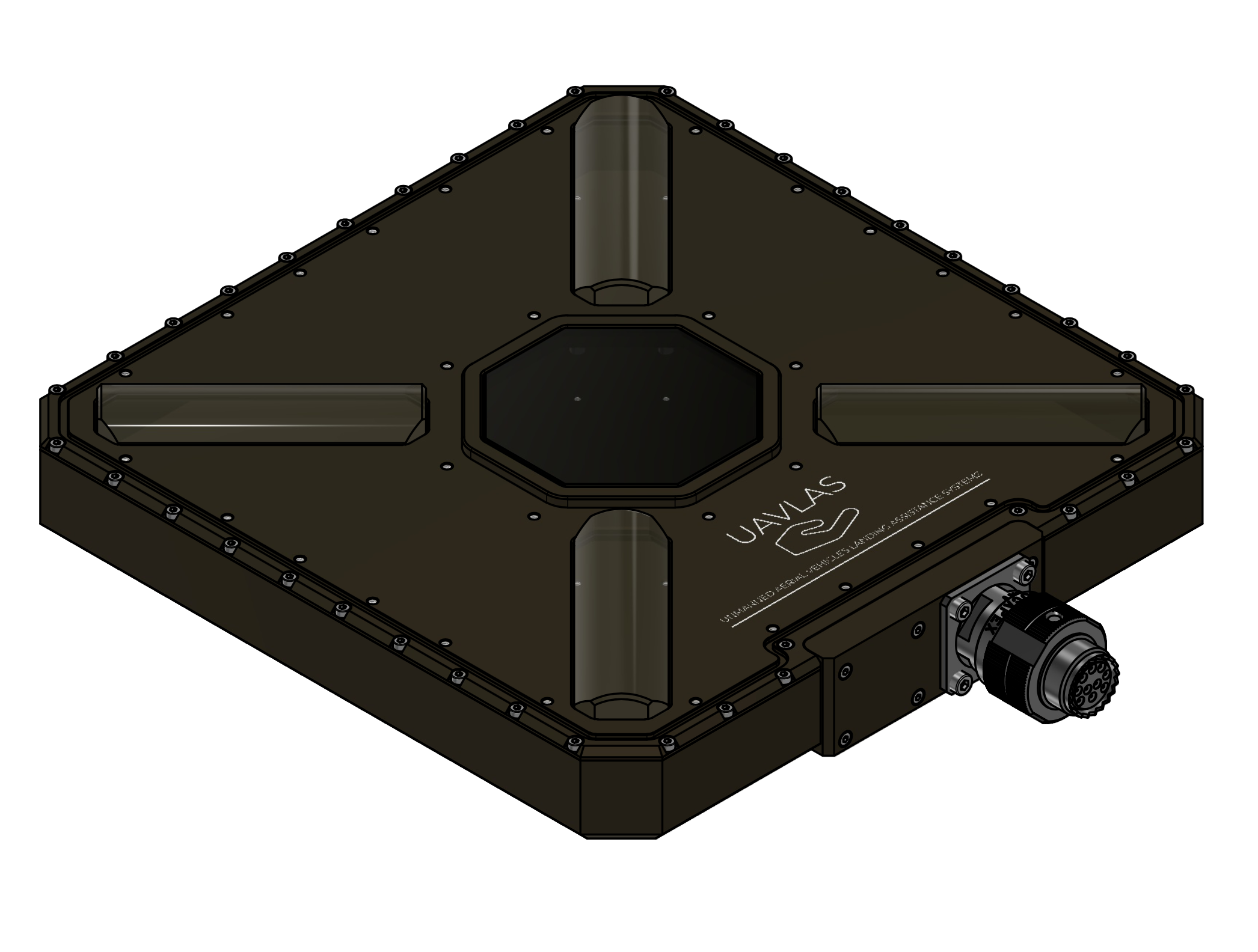
Figure: ULSDV-HL-G3-TX Transmitter
Receiver (Onboard Unit)
- Device code: ULSDV-HLXS-G3-RXM
- Primary function: Optical IR field sensor for precision positioning
- Optical central wavelength : 940nm
System architecture uses 2 identical RXM receiver units operating with the same priority.
Both RXM units are used for redundancy and for yaw orientation estimation using a triangular method in MRX mode.
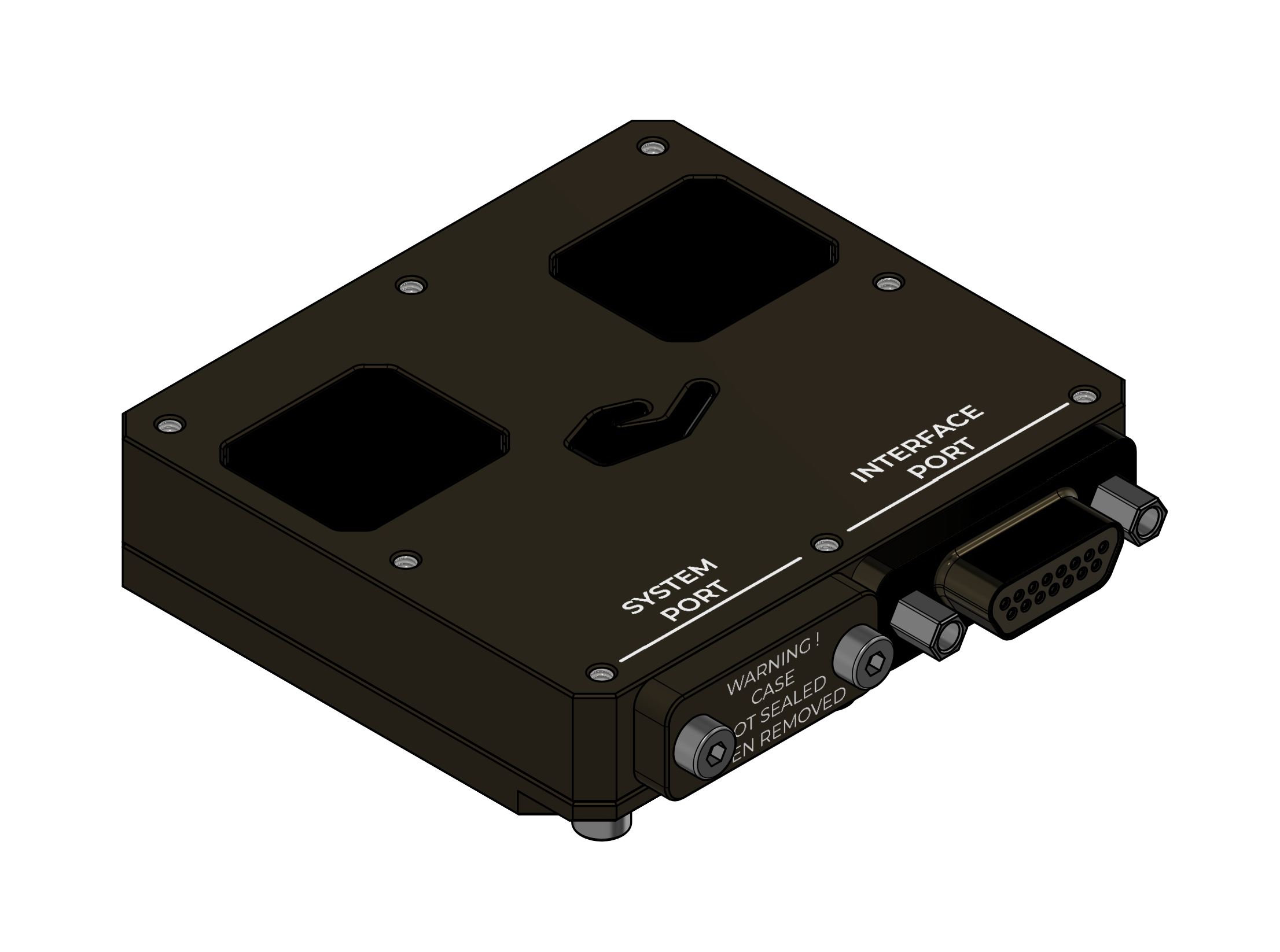
Figure: ULSDV-HLXS-G3-RXM Receiver
RS422–UART Onboard Adapter
When the autopilot has only a UART interface, the ULSDV-HLXS-G3 RS422-to-UART adapter (ULSDV-XX-UART-RS422) is used onboard to connect the ULSDV-HLXS-G3-RXM receiver to the autopilot.
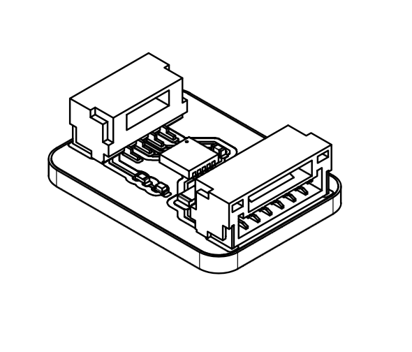
Figure: ULSDV-XX-UART-RS422 Onboard Adapter
USB–RS422 Ground Adapter
The ULSDV-XX-USB-RS422 adapter is used on the ground to connect the ULSDV-HL-G3-TX transmitter to a PC for configuration and control.
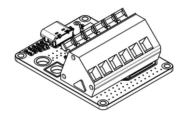
Figure: ULS-XX-USB-RS422 Ground Adapter
Key Features
- Dual RXM receiver architecture for redundancy and yaw estimation in MRX mode
- Shared generation 3 receiver platform for improved hardware commonality
- Optical transmitter-to-receiver link for precision positioning data transfer
- RS422-based native hardware interfaces with adapter support for UART-only autopilots
System Applications
- Precision landing and approach guidance
- Platform-relative positioning for autonomous aircraft operations
- Integration with supported autopilot and mission systems
System Wiring Schematics

Figure: HL/XS G3 Ground-Side Wiring Schematic

Figure: HL/XS G3 Onboard Wiring Schematic
Part Numbering
| Part Number | Description |
|---|---|
| ULS-HELI-G3 | System set with transmitter and 2 identical RXM receiver units. |
| ULSDV-HL-G3-TX | Transmitter unit. |
| ULSDV-HLXS-G3-RXM | RXM receiver unit (identical hardware for Set A and Set B), quantity 2 per system. |
| ULS-XX-UART-RS422 | RS422-to-UART onboard adapter for connecting RXM receiver to UART-only autopilots. |
| ULS-XX-USB-RS422 | USB-to-RS422 ground adapter for connecting transmitter to PC (configuration and control). |
| TVP00WCI-13-98P | Manufacturer Amphenol. Transmitter connector type. |
| TV06RW-13-98S | Manufacturer Amphenol. Transmitter cable connector type. |
| M83513/04-B06C | Receiver connector type. |
| M83513/03-B03C | Receiver cable connector type. |
Table: Part Numbering
System Specifications
| Parameter | Value |
|---|---|
| Distance range (m) | 30m…50m |
| Working angle (deg) | 60 |
| Data update frequency (Hz) | 20 |
| Receiver architecture | 2 identical RXM receivers with same priority |
| Redundancy mode | Dual-RXM redundancy |
| MRX yaw estimation method | Triangular method |
Table: Common Specification
| Parameter | Value |
|---|---|
| Field of view (deg) | 95 |
| Dimensions (mm) | 50x54 |
| Weight (g) | 50 |
| Power consumption (W) | 10 |
| Supply voltage (V) | +12V…+24V |
| Interfaces | CAN,USB,RS422 |
Table: ULSDV-HLXS-G3-RXM Receiver Specifications
| Parameter | Value |
|---|---|
| Field of emitting (deg) | 30 (60 in Wide Field) |
| Dimensions (mm) | 254 x 214 |
| Weight (g) | 1960 |
| Power consumption (W) | 20W |
| Supply voltage (V) | +18V..+24V |
| Interfaces | CAN, RS422 |
Table: ULSDV-HL-G3-TX Transmitter (Ground) Specifications
Interface Summary
The ULS-Heli-G3 system uses optical, RS422, CAN, USB, and adapter-assisted UART connectivity depending on subsystem role and host platform capability.
- Transmitter to receiver: optical IR link
- Transmitter to control PC: USB to RS422 adapter path
- Receiver to host system: native RS422, CAN, USB, or adapter-assisted UART
For connector, pinout, signal, and protocol definitions, refer to ULSDC-PBICD110426-ULS-Heli-G3-ICD.
Mechanical Dimensions
| Component | Dimensions (mm) | Notes |
|---|---|---|
| ULSDV-HLXS-G3-RXM (ULSDV-HLXS-G3-RXM) | ~ 50mm x 52mm | Without connector |
| ULSDV-HL-G3-TX | ~254mm x 214mm | Without connector |
Table: Mechanical Dimensions
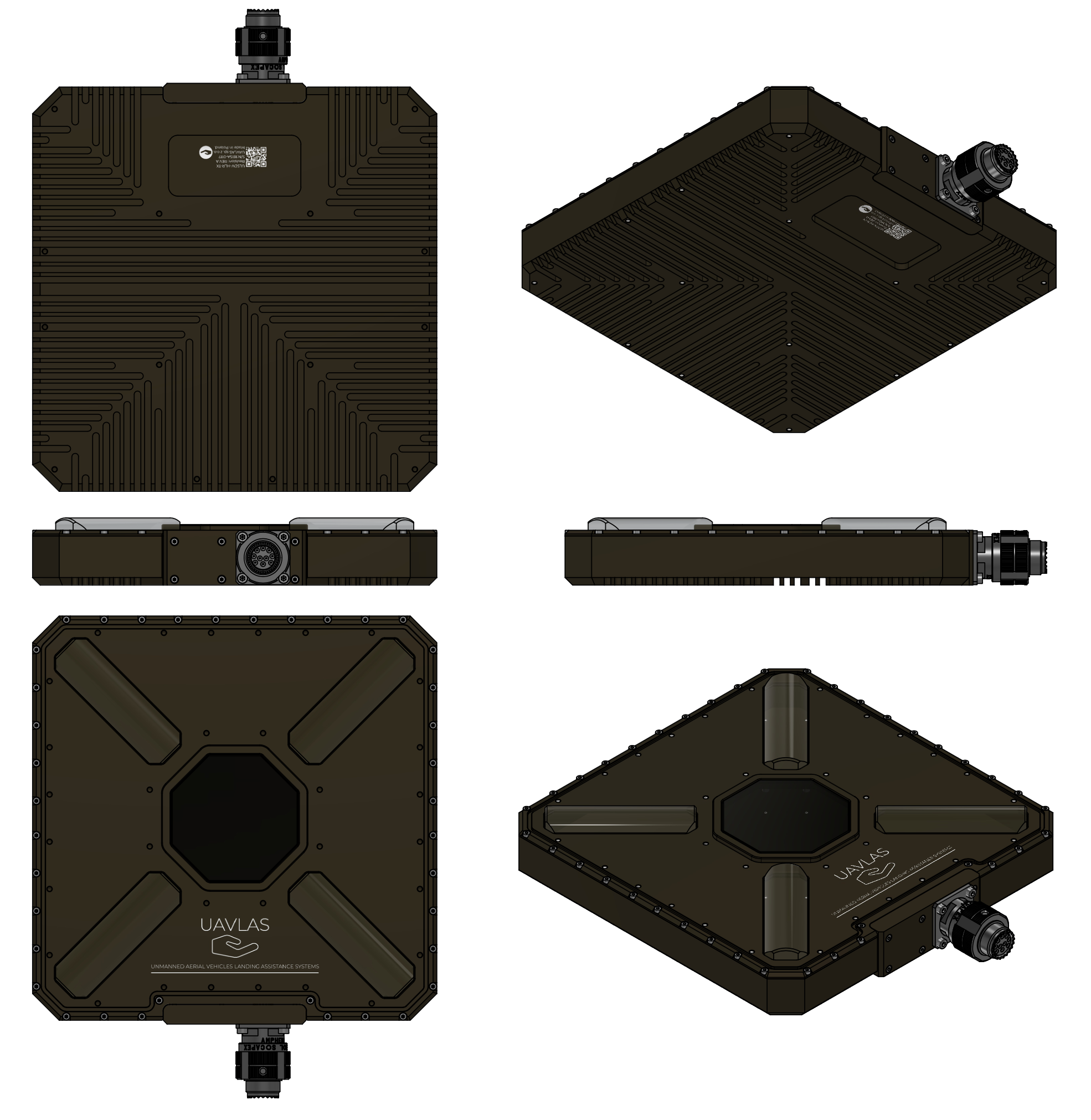
Figure: ULSDV-HL-G3-TX Projection Views (Color)
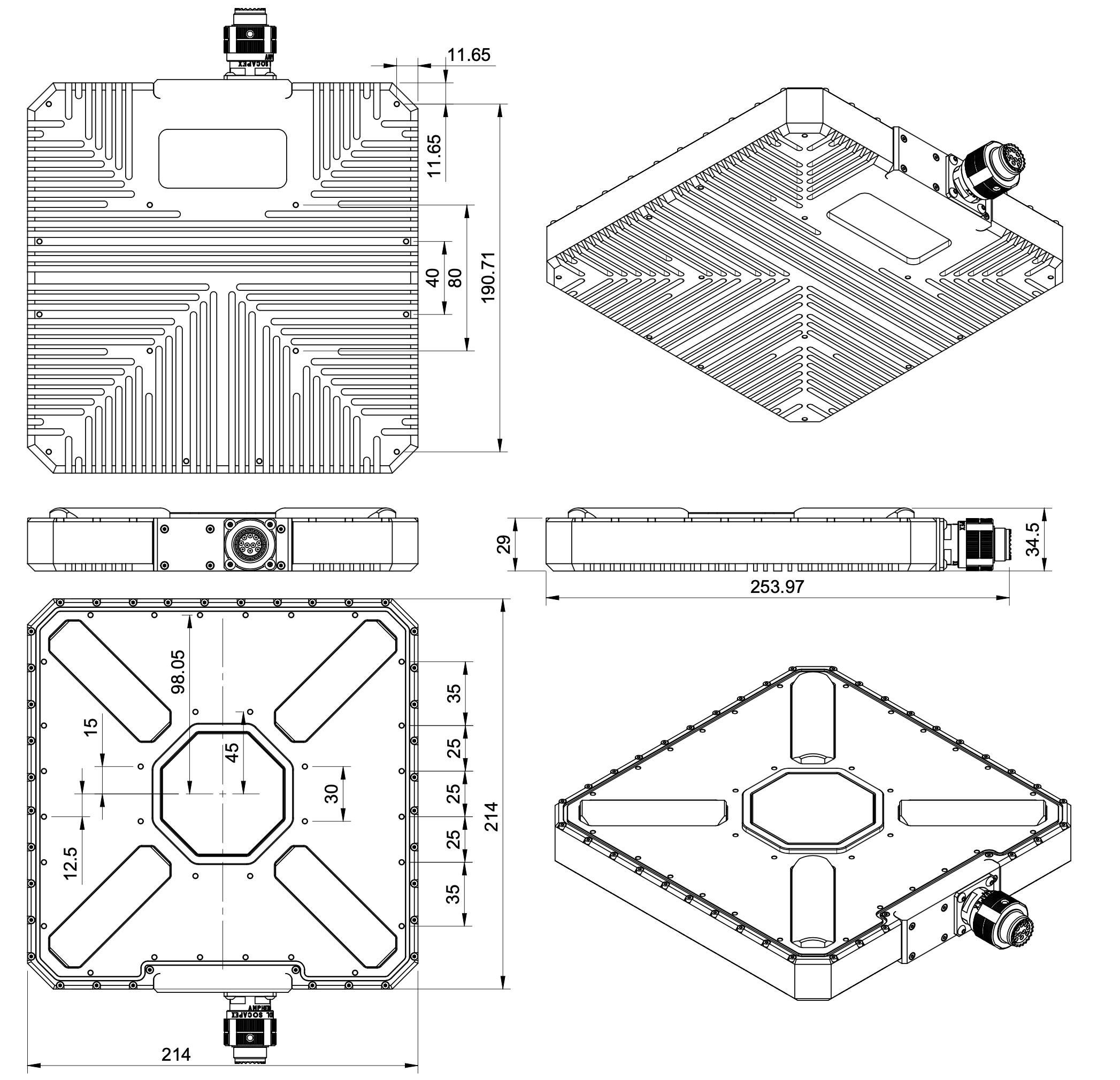
Figure: ULSDV-HL-G3-TX Transmitter Dimensions
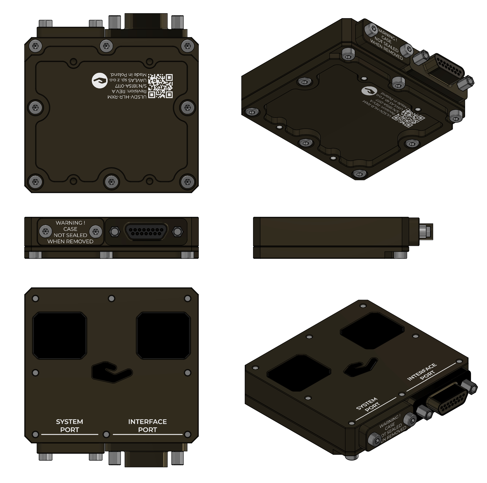
Figure: ULSDV-HLXS-G3-RXM Projection Views (Color)
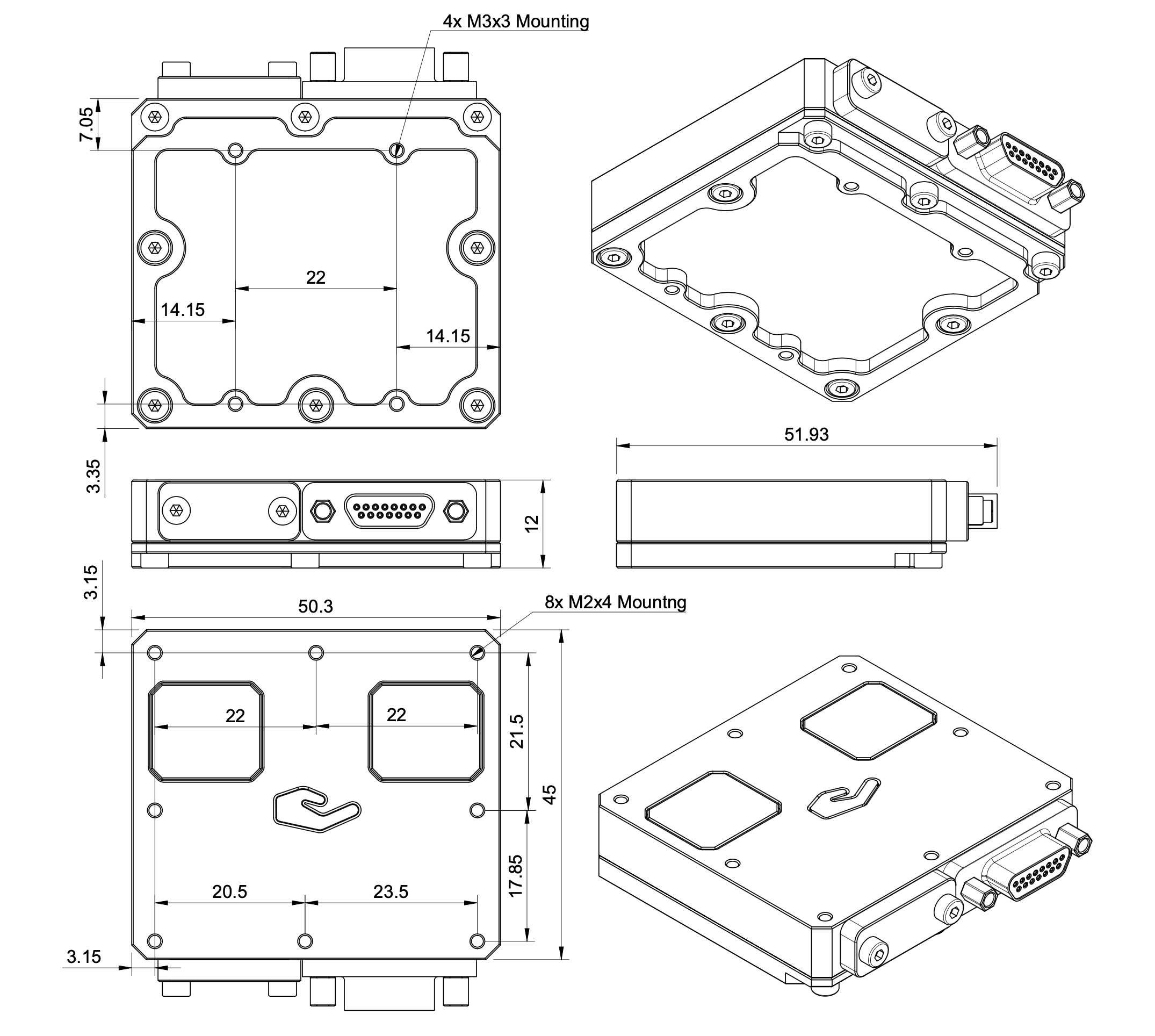
Figure: ULSDV-HLXS-G3-RXM Receiver Dimensions
Packaging Information
| Item | Packaging Value |
|---|---|
| Packaging type | Rugged case |
| Unit net weight | 2500 |
| Unit gross weight | 4500 |
| Box dimensions | 180x380x400 |
Table: Packaging Information
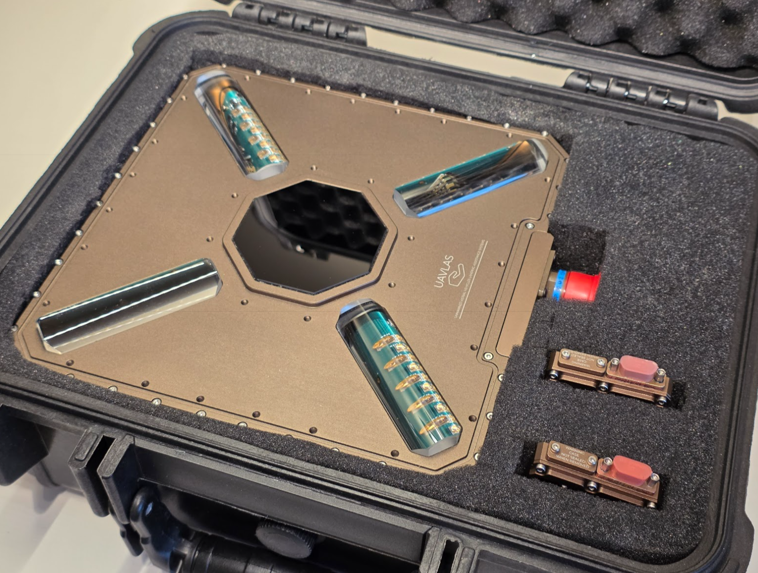
Figure: ULS-Heli-G3 packaging
Environmental Conditions
Equipment is designed to meet stringent military and maritime operational requirements, providing reliable performance in the most demanding environmental conditions including shipboard operations, offshore platforms, and tactical deployments.
Operating Temperature Range
- Extended operating range: -40°C to +85°C
- Meets MIL-STD-810 requirements for temperature extremes
- Arctic to desert operations capability
- No performance degradation across full temperature range
- Qualified for rapid temperature transitions and thermal shock
- Cold-soak start capability from -40°C
Humidity and Salt Fog Resistance
- Relative humidity: Up to 95% (condensing)
- Salt fog resistant per MIL-STD-810 Method 509
- Maritime environment qualified for shipboard operations
- Corrosion-resistant materials and protective coatings
- Protected against salt spray and marine atmosphere
- Suitable for offshore platform installations
Ingress Protection
- IP67 rated (Dust tight and water immersion resistant)
- 6 - Complete protection against dust, sand, and particulate ingress
- 7 - Protected against temporary immersion in water (up to 1 meter depth for 30 minutes)
- Exceeds requirements for shipboard and maritime operations
- Protected against:
- Heavy rain and sea spray
- Temporary submersion (deck washing, wave impact)
- Sand and dust storms
- Contaminated environments
Shock and Vibration
- Vibration: MIL-STD-810 Method 514
- Helicopter vibration profile qualified
- Shipboard vibration and shock resistant
- Continuous operation during vibration
- Mechanical Shock: MIL-STD-810 Method 516
- Drop and impact qualified
- Transportation and handling shock resistant
- Crash survival design considerations
Electromagnetic Compatibility
- EMI/EMC: MIL-STD-461 compliant
- Electromagnetic interference immunity
- Low electromagnetic emissions
- RF coexistence with military avionics
- Lightning protection per MIL-STD-464
- ESD Protection: IEC 61000-4-2
- Contact discharge: ±8kV
- Air discharge: ±15kV
Storage Conditions
- Storage temperature: -55°C to +85°C
- Relative humidity: Up to 95% (condensing)
- Long-term storage in uncontrolled environments
- Sealed for preservation and long-term depot storage
Altitude and Pressure
- Operating altitude: -500m to +4500m above sea level
- Storage altitude: -500m to +12000m
- Pressure differential resistant
- Suitable for high-altitude helicopter operations
Maintenance and Serviceability
- Designed for field maintenance and repair
- Minimal preventive maintenance required
- Accessible components for service and inspection
- Environmental seals serviceable in the field
- Long service intervals suitable for deployed operations
Note: All environmental specifications are subject to final qualification testing. Contact UAVLAS for the most current test data and certification documentation. Custom environmental testing and certification to specific standards available upon request.
Optical Radiation Safety (IR Emission)
The transmitter (ground unit) emits pulsed infrared optical radiation with a centre wavelength of 940nm. The receivers are optical sensors only and do not emit optical radiation.
INFRARED RADIATION IS EMITTED FROM THE TRANSMITTER OPTICAL APERTURES WHENEVER THE UNIT IS POWERED. Do not look into the transmitter emitter apertures at close range. IR emission at 940nm is invisible and does not trigger the blink or aversion reflex, so the eye receives no natural warning of exposure.
Why This Warning Is Given
Radiation at 940nm is outside the visible range. The protective mechanisms that limit exposure to bright visible sources — the blink reflex, pupil constriction, and the instinct to look away — are not triggered by an invisible source. Exposure time is therefore limited only by operator behaviour, which is why the precautions below are given as operating instructions and not left to the operator’s judgement.
The transmitter is a positioning beacon. It is not an illumination product and is not intended to be viewed at any time.
Operating Precautions
- Do not look directly into the transmitter emitter apertures from a distance of less than 1 metre while the unit is powered.
- Treat the transmitter as emitting whenever supply voltage is applied, including when no receiver is present and no positioning data is being transferred.
- Switch emission off before working directly in front of the transmitter. Use the Illumination parameter in ULS-Tools to disable emission, or disconnect supply power.
- Do not view the powered transmitter through binoculars, telescopes, camera lenses, magnifiers, or any other light-collecting instrument. Such optics concentrate the emission and can raise the exposure at the eye by orders of magnitude compared with unaided viewing.
- Do not add, remove, or modify optical elements of the transmitter. Added optics change the emission characteristics and invalidate any photobiological classification of the unit.
- Position the transmitter so that the emission field is directed away from work positions and walkways where personnel stay for extended periods.
- Servicing personnel working inside the emission field at close range should disable emission first rather than rely on viewing distance.
Classification and Applicable Standards
| Item | Value |
|---|---|
| Emitter type | Incoherent IR LED array (not a laser) |
| Centre wavelength | 940nm |
| Emission mode | Pulsed |
| Applicable standard | IEC 62471 / EN 62471, Photobiological safety of lamps and lamp systems |
| Classification distance | 200mm (non-GLS source, per IEC 62471) |
| Risk group | TBD — to be entered from the IEC 62471 assessment report |
| Hazard distance | TBD — to be entered from the IEC 62471 assessment report |
Table: Optical Radiation Safety Data
The transmitter uses light emitting diodes, not laser emitters. LED sources are assessed under IEC 62471; the laser product standard IEC 60825-1 does not apply to this product.
For a 940nm source the applicable exposure limits are the retinal thermal hazard (380nm to 1400nm), the retinal thermal hazard for a weak visual stimulus (780nm to 1400nm, which applies specifically to sources that give no visual cue), and the infrared hazard to the cornea and lens (780nm to 3000nm). The corneal and lens limits are intended for chronic exposures longer than 1000s at a daily averaged irradiance of 100 W/m² or more.
Organisations operating this equipment within the European Union are additionally subject to Directive 2006/25/EC on the exposure of workers to artificial optical radiation, which requires the employer to assess worker exposure against the exposure limit values given in Annex I of that directive. UAVLAS provides the emission data needed for that assessment on request.
Compliance and Standards
- Document classification and release control as defined in metadata
- Product-specific compliance statements to be finalized for release
Ordering Information
Use the part numbering section to identify system variants, subassemblies, and related accessories.
Change Control
All changes to this document must be reviewed and approved by the relevant technical leads and stakeholders
7.2 - ULS-Heli-G3 Interface Control Document
Interface Control Document ULSDC-PBICD110426, version 0.1.36
ULSDC-PBICD110426 · version 0.1.36 · issued April 11, 2026
The numbered PDF is the controlled copy: download it from the portal.
Introduction
Purpose
This document defines the interfaces between ULS-Heli-G3 components, including one transmitter and 2 identical, equal-priority RXM receivers. It records the mechanical, electrical, communication, and functional characteristics needed for correct system integration.
Scope
This document is intended for system engineers, integrators, and developers working with ULS-Heli-G3 systems.
Assumptions and Exclusions
- This document defines interfaces only; product selection and overview information belong in the datasheet.
- Installation, calibration, and operating procedures belong in the operation manual.
System Components
Transmitter (Ground Unit)
- Device code: ULSDV-HL-G3-TX
- Primary function: Optical IR field emission for precision positioning
- Optical emission parameters: 940nm, pulsed
Figure: ULSDV-HL-G3-TX Transmitter
Receiver (Onboard Unit)
- Device code: ULSDV-HLXS-G3-RXM
- Primary function: Optical IR field sensor for precision positioning
- Optical central wavelength : 940nm
System architecture uses 2 identical RXM receiver units operating with the same priority.
Both RXM units are used for redundancy and for yaw orientation estimation using a triangular method in MRX mode.
Figure: ULSDV-HLXS-G3-RXM Receiver
RS422–UART Onboard Adapter
When the autopilot has only a UART interface, the ULSDV-HLXS-G3 RS422-to-UART adapter (ULSDV-XX-UART-RS422) is used onboard to connect the ULSDV-HLXS-G3-RXM receiver to the autopilot.
Figure: ULSDV-XX-UART-RS422 Onboard Adapter
USB–RS422 Ground Adapter
The ULSDV-XX-USB-RS422 adapter is used on the ground to connect the ULSDV-HL-G3-TX transmitter to a PC for configuration and control.
Figure: ULS-XX-USB-RS422 Ground Adapter
Interface Overview

Figure: ULS-Heli-G3 System Interfaces Overview
Physical Interfaces

Figure: ULS-Heli-G3 System Interfaces Overview
Transmitter to Control PC Interface
The transmitter (ULSDV-HL-G3-TX) connects to a PC via the ULS-XX-USB-RS422 ground adapter for configuration and control.
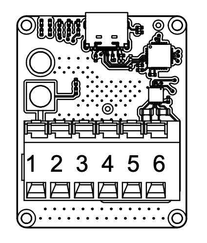
Figure: ULS-XX-USB-RS422 Adapter Pinout
| Pin | Function |
|---|---|
| 1 | +V supply +18V…+27V to Transmitter |
| 2 | GND |
| 3 | RS422 A RX+ (Adapter Input) |
| 4 | RS422 B RX- (Adapter Input) |
| 5 | RS422 Y TX- (Adapter Output) |
| 6 | RS422 Z TX+ (Adapter Output) |
| 7,8 | +V supply +18V…+27V Power input from battery |
*Table: ULS-XX-USB-RS422 Pinout *
Data Types
- Status information
- Control signals
- Transmitter configuration
- External IMU/COMPASS data
Connection Types
- CAN Bus – For network communication
- USB – Via ULS-XX-USB-RS422 adapter (PC side)
- RS422 – Native transmitter interface; for serial communication with external sensors
Transmitter Pinout
ULSDV-HL-G3-TX Transmitter pinout information.
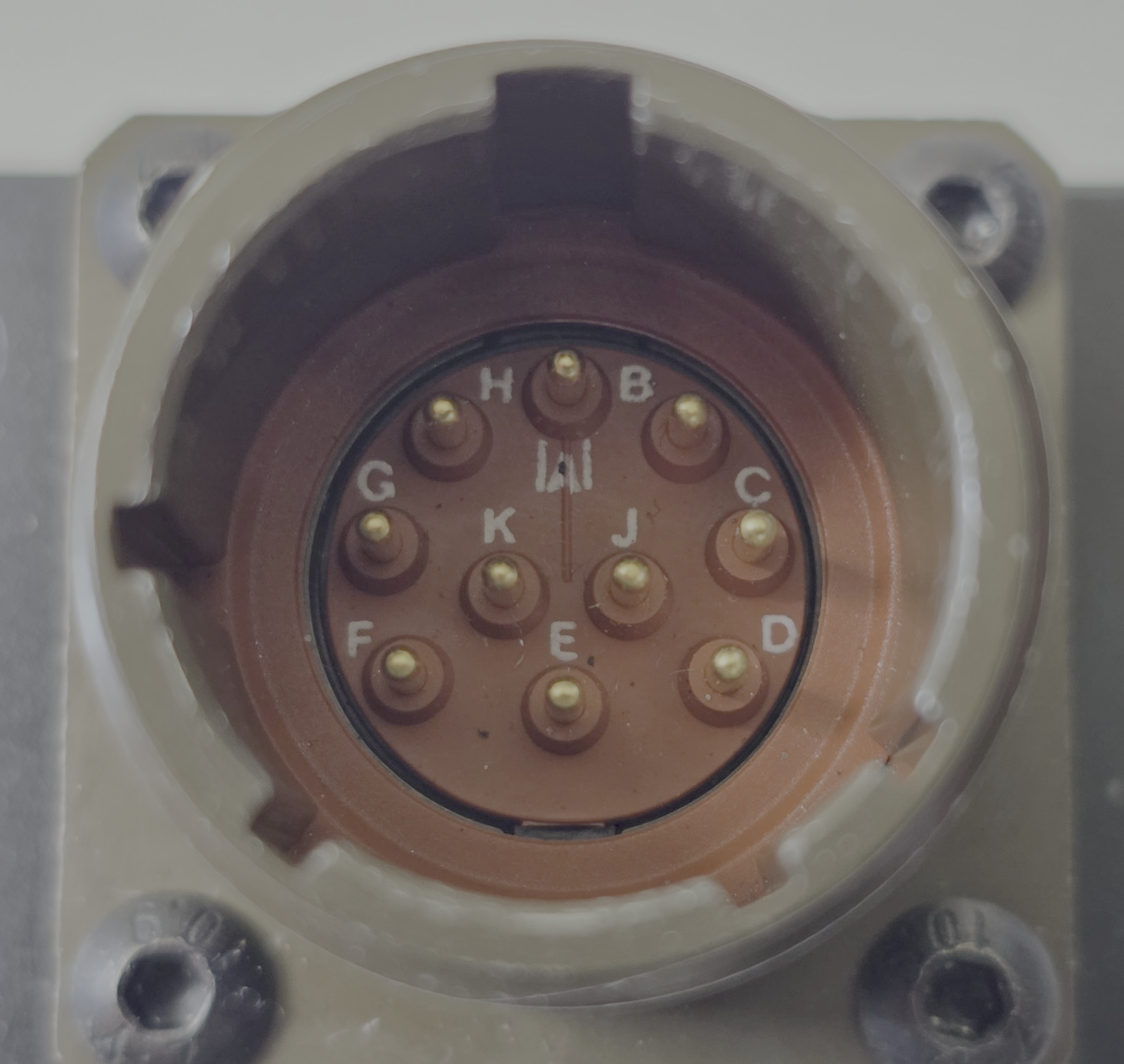
Figure: Transmitter connector
| Pin | Function |
|---|---|
| A | +V supply +18V…+27V |
| B | RS422 RX+ (A) |
| C | RS422 RX- (B) |
| D | RS422 TX+ (Y) |
| E | RS422 TX- (Z) |
| F | GND |
| G | C1L |
| H | C1H |
| J | GND |
| K | GND |
Table: Transmitter Connector Pinout (ULSDV-HL-G3-TX)
Do not connect or disconnect the transmitter interface under power unless approved by final hardware instructions.
Transmitter to Receiver Interface
The transmitter and receiver use an optical interface to exchange data. Transmission uses pulsed IR emission at 940 nanometers. Data transmission is only in the direction from the transmitter to the receiver.
Data Types
- Position encoded
- Status encoded data (transmitter orientation and instructions)
Connection Type
- Optical IR 940nm (pulsed) – Infrared optical link
The transmitter emits invisible infrared radiation whenever it is powered. Observe the precautions in the Optical Radiation Safety section before working in front of the transmitter.
Receiver Interfaces (RXM Set A and RXM Set B)
Both RXM receivers (ULSDV-HLXS-G3-RXM) are identical and have the same priority in system operation.
When the autopilot provides only a UART interface, connect the RXM receiver RS422 output through the ULS-XX-UART-RS422 onboard adapter.
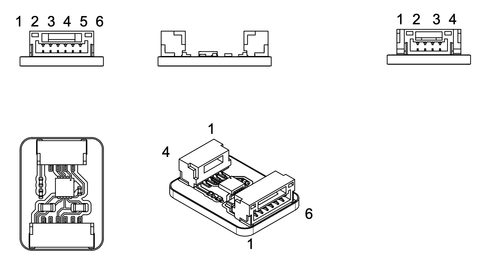
Figure: ULS-XX-UART-RS422 Adapter Pinout
| Pin | Function |
|---|---|
| 1 | +5V |
| 2 | UART-TX (Adapter Out) |
| 3 | UART-RX (Adapter In) |
| 4 | GND |
Table: ULSDV-XX-UART-RS422-R0 4 pin connector pinout
| Pin | Function |
|---|---|
| 1 | GND |
| 3 | RS422 A RX+ (Adapter Input) |
| 4 | RS422 B RX- (Adapter Input) |
| 5 | RS422 Y TX- (Adapter Output) |
| 6 | RS422 Z TX+ (Adapter Output) |
| 2 | GND |
Table: ULSDV-XX-UART-RS422-R0 6 pin connector pinout
Data Types
- MAVLink messages
- ULS-Blitz frames
- ASCII protocol
- MRX-mode yaw estimation data (triangular method)
Connection Types
- RS422 – Native receiver interface
- UART – Via ULS-XX-UART-RS422 adapter (for UART-only autopilots)
- CAN – Network communication
- USB – Direct PC connection
Receiver Pinout
ULSDV-HLXS-G3-RXM Receiver pinout information.
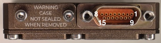
Figure: Receiver connector
| Pin | Function |
|---|---|
| 1 | + V supply +12V..+25V |
| 2 | C2H |
| 3 | C2L |
| 4 | GND - Ground connection |
| 5 | + V supply +12V..+25V |
| 6 | C1H |
| 7 | C1L |
| 8 | GND - Ground connection |
| 9 | + V supply +12V..+25V |
| 10 | RS422 Z |
| 11 | RS422 Y |
| 12 | RS422 A |
| 13 | RS422 B |
| 14 | GND - Ground connection |
| 15 | GND - Ground connection |
Table: ULSDV-HLXS-G3-RXM Connector Pinout
For receiver setup unscrew protection part to get access to usb connector.
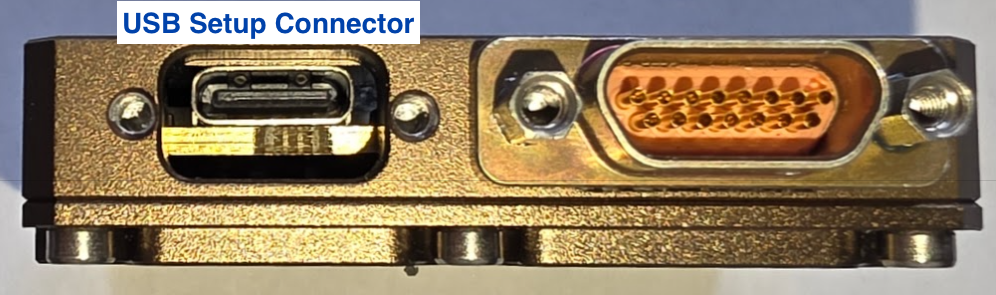
Figure: Receiver USB connector
Due hardware limitation of current revision USB connector with thin shield required
Receiver case not sealed when USB cover removed.
Electrical Interfaces

Figure: Power Distribution and Connections
Transmitter Electrical Characteristics
| Parameter | Value | Unit | Notes |
|---|---|---|---|
| Supply Voltage | +18…+26 | V | |
| Supply Current | 2.5 | A | |
| Power Consumption | 25 | W |
Table: Transmitter Electrical Specifications
Receiver Electrical Characteristics (Per RXM Set)
| Parameter | Value | Unit | Notes |
|---|---|---|---|
| Supply Voltage | +12…+26 | V | |
| Supply Current | 1 | A | |
| Power Consumption | 10 | W |
Table: Receiver Electrical Specifications
Communication Interfaces
Supported Communication Methods
- Optical IR 940nm pulsed link between transmitter and receiver
- RS422 for native wired subsystem interfaces
- UART via ULS-XX-UART-RS422 where required by the host autopilot
- CAN for network communication
- USB for direct PC access where supported
Data Definitions
Data Categories
- Position-encoded optical data
- Transmitter status and orientation data
- MAVLink messages
- ULS-Blitz frames
- ASCII protocol data
- MRX yaw estimation data
Functional Interfaces

Figure: Data Flow and Functional Interfaces
Data Exchange
The ULS-Heli-G3 system data exchange mechanism:
Control PC Functions:
- Configure and view status of transmitter
- Set configuration of receivers
- Send control signals (On/off, compass override information)
External Equipment:
- External IMU/Compass equipment can be used to override internal IMU/compass information
Receiver Functions:
- Accept data from transmitter over IR signal (position field information and ground unit IMU data)
- Accept NED and Attitude information from autopilot to convert coordinate system
- Multiple receivers (MRX mode) communicate to calculate vehicle orientation (YAW) using triangular method
- Send position offset data to autopilot
Mechanical Interfaces
| Component | Dimensions (mm) | Notes |
|---|---|---|
| ULSDV-HLXS-G3-RXM (ULSDV-HLXS-G3-RXM) | ~ 50mm x 52mm | Without connector |
| ULSDV-HL-G3-TX | ~254mm x 214mm | Without connector |
Table: Mechanical Dimensions
Figure: ULSDV-HL-G3-TX Projection Views (Color)
Figure: ULSDV-HL-G3-TX Transmitter Dimensions
Figure: ULSDV-HLXS-G3-RXM Projection Views (Color)
Figure: ULSDV-HLXS-G3-RXM Receiver Dimensions
Environmental Conditions
Equipment is designed to meet stringent military and maritime operational requirements, providing reliable performance in the most demanding environmental conditions including shipboard operations, offshore platforms, and tactical deployments.
Operating Temperature Range
- Extended operating range: -40°C to +85°C
- Meets MIL-STD-810 requirements for temperature extremes
- Arctic to desert operations capability
- No performance degradation across full temperature range
- Qualified for rapid temperature transitions and thermal shock
- Cold-soak start capability from -40°C
Humidity and Salt Fog Resistance
- Relative humidity: Up to 95% (condensing)
- Salt fog resistant per MIL-STD-810 Method 509
- Maritime environment qualified for shipboard operations
- Corrosion-resistant materials and protective coatings
- Protected against salt spray and marine atmosphere
- Suitable for offshore platform installations
Ingress Protection
- IP67 rated (Dust tight and water immersion resistant)
- 6 - Complete protection against dust, sand, and particulate ingress
- 7 - Protected against temporary immersion in water (up to 1 meter depth for 30 minutes)
- Exceeds requirements for shipboard and maritime operations
- Protected against:
- Heavy rain and sea spray
- Temporary submersion (deck washing, wave impact)
- Sand and dust storms
- Contaminated environments
Shock and Vibration
- Vibration: MIL-STD-810 Method 514
- Helicopter vibration profile qualified
- Shipboard vibration and shock resistant
- Continuous operation during vibration
- Mechanical Shock: MIL-STD-810 Method 516
- Drop and impact qualified
- Transportation and handling shock resistant
- Crash survival design considerations
Electromagnetic Compatibility
- EMI/EMC: MIL-STD-461 compliant
- Electromagnetic interference immunity
- Low electromagnetic emissions
- RF coexistence with military avionics
- Lightning protection per MIL-STD-464
- ESD Protection: IEC 61000-4-2
- Contact discharge: ±8kV
- Air discharge: ±15kV
Storage Conditions
- Storage temperature: -55°C to +85°C
- Relative humidity: Up to 95% (condensing)
- Long-term storage in uncontrolled environments
- Sealed for preservation and long-term depot storage
Altitude and Pressure
- Operating altitude: -500m to +4500m above sea level
- Storage altitude: -500m to +12000m
- Pressure differential resistant
- Suitable for high-altitude helicopter operations
Maintenance and Serviceability
- Designed for field maintenance and repair
- Minimal preventive maintenance required
- Accessible components for service and inspection
- Environmental seals serviceable in the field
- Long service intervals suitable for deployed operations
Note: All environmental specifications are subject to final qualification testing. Contact UAVLAS for the most current test data and certification documentation. Custom environmental testing and certification to specific standards available upon request.
Optical Radiation Safety (IR Emission)
The transmitter (ground unit) emits pulsed infrared optical radiation with a centre wavelength of 940nm. The receivers are optical sensors only and do not emit optical radiation.
INFRARED RADIATION IS EMITTED FROM THE TRANSMITTER OPTICAL APERTURES WHENEVER THE UNIT IS POWERED. Do not look into the transmitter emitter apertures at close range. IR emission at 940nm is invisible and does not trigger the blink or aversion reflex, so the eye receives no natural warning of exposure.
Why This Warning Is Given
Radiation at 940nm is outside the visible range. The protective mechanisms that limit exposure to bright visible sources — the blink reflex, pupil constriction, and the instinct to look away — are not triggered by an invisible source. Exposure time is therefore limited only by operator behaviour, which is why the precautions below are given as operating instructions and not left to the operator’s judgement.
The transmitter is a positioning beacon. It is not an illumination product and is not intended to be viewed at any time.
Operating Precautions
- Do not look directly into the transmitter emitter apertures from a distance of less than 1 metre while the unit is powered.
- Treat the transmitter as emitting whenever supply voltage is applied, including when no receiver is present and no positioning data is being transferred.
- Switch emission off before working directly in front of the transmitter. Use the Illumination parameter in ULS-Tools to disable emission, or disconnect supply power.
- Do not view the powered transmitter through binoculars, telescopes, camera lenses, magnifiers, or any other light-collecting instrument. Such optics concentrate the emission and can raise the exposure at the eye by orders of magnitude compared with unaided viewing.
- Do not add, remove, or modify optical elements of the transmitter. Added optics change the emission characteristics and invalidate any photobiological classification of the unit.
- Position the transmitter so that the emission field is directed away from work positions and walkways where personnel stay for extended periods.
- Servicing personnel working inside the emission field at close range should disable emission first rather than rely on viewing distance.
Classification and Applicable Standards
| Item | Value |
|---|---|
| Emitter type | Incoherent IR LED array (not a laser) |
| Centre wavelength | 940nm |
| Emission mode | Pulsed |
| Applicable standard | IEC 62471 / EN 62471, Photobiological safety of lamps and lamp systems |
| Classification distance | 200mm (non-GLS source, per IEC 62471) |
| Risk group | TBD — to be entered from the IEC 62471 assessment report |
| Hazard distance | TBD — to be entered from the IEC 62471 assessment report |
Table: Optical Radiation Safety Data
The transmitter uses light emitting diodes, not laser emitters. LED sources are assessed under IEC 62471; the laser product standard IEC 60825-1 does not apply to this product.
For a 940nm source the applicable exposure limits are the retinal thermal hazard (380nm to 1400nm), the retinal thermal hazard for a weak visual stimulus (780nm to 1400nm, which applies specifically to sources that give no visual cue), and the infrared hazard to the cornea and lens (780nm to 3000nm). The corneal and lens limits are intended for chronic exposures longer than 1000s at a daily averaged irradiance of 100 W/m² or more.
Organisations operating this equipment within the European Union are additionally subject to Directive 2006/25/EC on the exposure of workers to artificial optical radiation, which requires the employer to assess worker exposure against the exposure limit values given in Annex I of that directive. UAVLAS provides the emission data needed for that assessment on request.
Integration Wiring Diagrams
Figure: HL/XS G3 Ground-Side Wiring Schematic
Figure: HL/XS G3 Onboard Wiring Schematic
Part Numbering
| Part Number | Description |
|---|---|
| ULS-HELI-G3 | System set with transmitter and 2 identical RXM receiver units. |
| ULSDV-HL-G3-TX | Transmitter unit. |
| ULSDV-HLXS-G3-RXM | RXM receiver unit (identical hardware for Set A and Set B), quantity 2 per system. |
| ULS-XX-UART-RS422 | RS422-to-UART onboard adapter for connecting RXM receiver to UART-only autopilots. |
| ULS-XX-USB-RS422 | USB-to-RS422 ground adapter for connecting transmitter to PC (configuration and control). |
| TVP00WCI-13-98P | Manufacturer Amphenol. Transmitter connector type. |
| TV06RW-13-98S | Manufacturer Amphenol. Transmitter cable connector type. |
| M83513/04-B06C | Receiver connector type. |
| M83513/03-B03C | Receiver cable connector type. |
Table: Part Numbering
Applicable Documents
- ULSDC-PBDS110426-ULS-Heli-G3-Datasheet
- ULSDC-PBOM110426-ULS-Heli-G3-Operation-Manual
- ULSDC-PBDS051125-ULS-DeCoNet Blitz Messages Specification
Change Control
All changes to this document must be reviewed and approved by the relevant technical leads and stakeholders
7.3 - ULS-Heli-G3 Operation Manual
Operation Manual ULSDC-PBOM110426, version 0.1.22
ULSDC-PBOM110426 · version 0.1.22 · issued April 11, 2026
The numbered PDF is the controlled copy: download it from the portal.
Introduction
Purpose
This manual provides installation, configuration, operation, verification, and troubleshooting guidance for the ULS-Heli-G3 system.
Scope
This manual covers one transmitter and 2 identical, equal-priority RXM receivers used in the ULS-Heli-G3 architecture.
Intended Audience
This manual is intended for operators, installers, technicians, and integrators responsible for commissioning and using the system.
Safety Information
- WARNING: The transmitter emits invisible infrared radiation when powered. Do not look into the emitter apertures at close range. See the Optical Radiation Safety section below.
- CAUTION: Do not connect or disconnect the transmitter interface under power.
Optical Radiation Safety (IR Emission)
The transmitter (ground unit) emits pulsed infrared optical radiation with a centre wavelength of 940nm. The receivers are optical sensors only and do not emit optical radiation.
INFRARED RADIATION IS EMITTED FROM THE TRANSMITTER OPTICAL APERTURES WHENEVER THE UNIT IS POWERED. Do not look into the transmitter emitter apertures at close range. IR emission at 940nm is invisible and does not trigger the blink or aversion reflex, so the eye receives no natural warning of exposure.
Why This Warning Is Given
Radiation at 940nm is outside the visible range. The protective mechanisms that limit exposure to bright visible sources — the blink reflex, pupil constriction, and the instinct to look away — are not triggered by an invisible source. Exposure time is therefore limited only by operator behaviour, which is why the precautions below are given as operating instructions and not left to the operator’s judgement.
The transmitter is a positioning beacon. It is not an illumination product and is not intended to be viewed at any time.
Operating Precautions
- Do not look directly into the transmitter emitter apertures from a distance of less than 1 metre while the unit is powered.
- Treat the transmitter as emitting whenever supply voltage is applied, including when no receiver is present and no positioning data is being transferred.
- Switch emission off before working directly in front of the transmitter. Use the Illumination parameter in ULS-Tools to disable emission, or disconnect supply power.
- Do not view the powered transmitter through binoculars, telescopes, camera lenses, magnifiers, or any other light-collecting instrument. Such optics concentrate the emission and can raise the exposure at the eye by orders of magnitude compared with unaided viewing.
- Do not add, remove, or modify optical elements of the transmitter. Added optics change the emission characteristics and invalidate any photobiological classification of the unit.
- Position the transmitter so that the emission field is directed away from work positions and walkways where personnel stay for extended periods.
- Servicing personnel working inside the emission field at close range should disable emission first rather than rely on viewing distance.
Classification and Applicable Standards
| Item | Value |
|---|---|
| Emitter type | Incoherent IR LED array (not a laser) |
| Centre wavelength | 940nm |
| Emission mode | Pulsed |
| Applicable standard | IEC 62471 / EN 62471, Photobiological safety of lamps and lamp systems |
| Classification distance | 200mm (non-GLS source, per IEC 62471) |
| Risk group | TBD — to be entered from the IEC 62471 assessment report |
| Hazard distance | TBD — to be entered from the IEC 62471 assessment report |
Table: Optical Radiation Safety Data
The transmitter uses light emitting diodes, not laser emitters. LED sources are assessed under IEC 62471; the laser product standard IEC 60825-1 does not apply to this product.
For a 940nm source the applicable exposure limits are the retinal thermal hazard (380nm to 1400nm), the retinal thermal hazard for a weak visual stimulus (780nm to 1400nm, which applies specifically to sources that give no visual cue), and the infrared hazard to the cornea and lens (780nm to 3000nm). The corneal and lens limits are intended for chronic exposures longer than 1000s at a daily averaged irradiance of 100 W/m² or more.
Organisations operating this equipment within the European Union are additionally subject to Directive 2006/25/EC on the exposure of workers to artificial optical radiation, which requires the employer to assess worker exposure against the exposure limit values given in Annex I of that directive. UAVLAS provides the emission data needed for that assessment on request.
System Overview
ULS-Heli-G3 is a generation 3 precision optical positioning system built around one ground transmitter and 2 equal-priority RXM receivers. The system supports redundant onboard sensing and MRX-based yaw estimation for platform-relative positioning and landing support.
Package Contents
- 1x Ground transmitter unit
- 2x RXM receiver units.
- 1x ULS-XX-USB-RS422 adapter (ground configuration)
- 2x ULS-XX-UART-RS422 onboard adapters (receiver-to-autopilot UART interface)
- Cables and mounting hardware
- Documentation package (may supply in online form )
Installation
Wiring Schematics
Figure: HL/XS G3 Ground-Side Wiring Schematic
Figure: HL/XS G3 Onboard Wiring Schematic
Transmitter Installation
Figure: ULSDV-HL-G3-TX Transmitter
Figure: ULSDV-HL-G3-TX Dimensions
- Mounting instructions: device can be mounter from top side or from bottom side. Use corresponding M3 screws to mount device on place. 3D model and pad example can be provided by UAVLAS under request.
- Orientation requirements: The device must be positioned with the optical elements facing upward. Make sure that no foreign objects obstruct the optical elements within the transmitter’s entire field of view.
Receiver Installation
Figure: ULSDV-HLXS-G3-RXM Receiver
Figure: ULSDV-HLXS-G3-RXM Dimensions
- Receivers location and orientation: The device must be positioned with the optical elements facing downward. Ensure that the optical elements are not obstructed by foreign objects within the transmitter’s entire field of view.
- Install the receivers at least 0.5 meters apart; this will ensure reliable operation in MRX mode even if one of the transmitters moves out of the system’s field of view.Typically, the first receiver (the one connected to the main autopilot) is located near the center of the landing point, and the second receiver is located at the tail. The maximum installation distance is 3 meters.
Configuration
Connecting Transmitter to PC
Use the ULS-XX-USB-RS422 adapter to connect the transmitter RS422 interface to a PC USB port for configuration and control via ULS-Tools software.
Figure: ULS-XX-USB-RS422 Ground Adapter
Figure: ULS-XX-USB-RS422 Adapter Pinout
Connecting Receiver to UART Autopilot
When the autopilot provides only a UART interface, use the ULS-XX-UART-RS422 onboard adapter between the receiver RS422 output and the autopilot UART port.
Figure: ULS-XX-UART-RS422 Onboard Adapter
Figure: ULS-XX-UART-RS422 Onboard Adapter Pinout
Receiver Pinout
ULSDV-HLXS-G3-RXM Receiver pinout information.
Figure: Receiver connector
| Pin | Function |
|---|---|
| 1 | + V supply +12V..+25V |
| 2 | C2H |
| 3 | C2L |
| 4 | GND - Ground connection |
| 5 | + V supply +12V..+25V |
| 6 | C1H |
| 7 | C1L |
| 8 | GND - Ground connection |
| 9 | + V supply +12V..+25V |
| 10 | RS422 Z |
| 11 | RS422 Y |
| 12 | RS422 A |
| 13 | RS422 B |
| 14 | GND - Ground connection |
| 15 | GND - Ground connection |
Table: ULSDV-HLXS-G3-RXM Connector Pinout
For receiver setup unscrew protection part to get access to usb connector.
Figure: Receiver USB connector
Due hardware limitation of current revision USB connector with thin shield required
Receiver case not sealed when USB cover removed.
Transmitter Pinout
ULSDV-HL-G3-TX Transmitter pinout information.
Figure: Transmitter connector
| Pin | Function |
|---|---|
| A | +V supply +18V…+27V |
| B | RS422 RX+ (A) |
| C | RS422 RX- (B) |
| D | RS422 TX+ (Y) |
| E | RS422 TX- (Z) |
| F | GND |
| G | C1L |
| H | C1H |
| J | GND |
| K | GND |
Table: Transmitter Connector Pinout (ULSDV-HL-G3-TX)
Do not connect or disconnect the transmitter interface under power unless approved by final hardware instructions.
Device Configuration and Integration in ULS-Tools
ULS-Heli-G3 is currently in pre-production stage. Use ULS-Tools Beta for configuration and firmware update:
https://github.com/UAVLAS/ULSTools-Beta/releases/
Use the adapters listed in this manual to connect each device to a PC and complete configuration in ULS-Tools before field operation.
ULS-Tools Device Dashboard
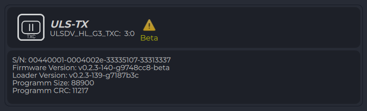
Figure: ULS-Tools Device Dashboard
Configure Transmitter
- Connect the transmitter through the ULS-XX-USB-RS422 adapter.
- Open transmitter settings and verify communication parameters.
- Set required operating parameters and click Apply Config.
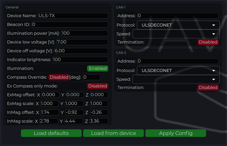
Figure: ULS-Tools Transmitter Configuration
| Parameter | Description |
|---|---|
| Device Name | Name shown for the transmitter in ULS-Tools. |
| Beacon ID | Transmitter iD to be transmitter to receiver over R signal (functionality under request) |
| Device Illumination Power | IR emitter power scaling (100 for nominal operation). |
| Device Low Voltage | Voltage level where low-voltage warning is activated. |
| Device Off Voltage | Voltage level where IR emitters are disabled to prevent over-discharge. |
| Indicator Brightness | Brightness level of the transmitter status LED indicator. |
| Illumination | Enables or disables transmitter emission during configuration and operation. |
| Compass Override [deg] | Fixed heading override for installations that require manual heading alignment. |
| External Compass Only | Forces system to use only external compass data when enabled. |
| Magnetometer Offset/Scale | Calibration values for internal or external (“Ex”) magnetometer. |
| CAN Address/Speed | CAN bus node address and bitrate settings. |
| CAN Protocol | Protocol selection (ULS DECENT with ULSBlitz messages supported) Custom protocols are possible |
| CAN Termination | If system has inbuilt termination resistor this option can activate it |
Table: Transmitter Configuration Parameters
Configure Receiver (RXM)
- Connect each receiver and configure one at a time.
- Set UART protocol/baud rate to match autopilot serial configuration.
- For dual-receiver installation, verify MRX-related parameters and offsets.
- Click Apply Config after each update.
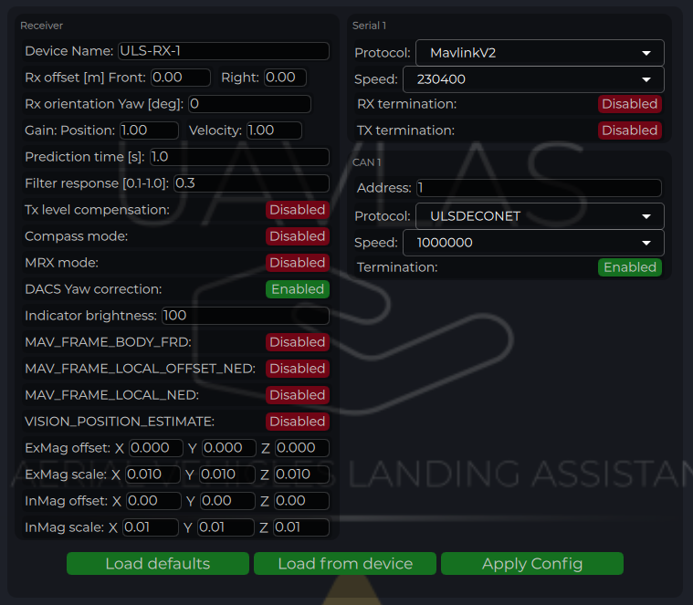
Figure: ULS-Tools Receiver Configuration
| Parameter | Description |
|---|---|
| Device Name | Name shown for the receiver in ULS-Tools. |
| Receiver Offset (Front, Right) [m] | Receiver position relative to vehicle reference point for MRX/yaw calculations. |
| Rx orientation | Receiver YAW installation orientation relative to vehicle front |
| Prediction Time [s] | Position prediction window used to smooth short signal interruptions. |
| Filter Response | Receiver position filter response tuning (higher is faster, lower is smoother). |
| Tx Level Compensation | Compensation for transmitter pan/tilt motion on moving platforms. |
| Compass Mode | Enables use of ground compass data in receiver calculations. |
| MRX Mode | Enables dual-receiver mode for yaw and redundancy features. |
| DACS Yaw Correction | Disable and enable Distance and Azimuth Correction System |
| Indicator Brightness | Brightness level of receiver status indicator. |
| Magnetometer Offset/Scale | Calibration values for internal or external (“Ex”) magnetometer. (under implementation) |
| CAN Address/Speed | CAN bus node address and bitrate settings. |
| CAN Protocol | Protocol selection (ULS DECENT with ULSBlitz messages supported) Custom protocols are possible |
| CAN Termination | If system has inbuilt termination resistor this option can activate it |
| UART Protocol | Protocol selection for autopilot communication (for example MavlinkV2). |
| UART Baud Rate | Serial baud rate; must match autopilot serial port settings. |
| UART Termination | If system has inbuilt termination resistor this option can activate it |
Table: Receiver Configuration Parameters
Compass Calibration (Ground Unit)
After installation, check compass behavior and perform calibration if required.
- Press Reset calibrations.
- Rotate the ground unit through multiple orientations to fill calibration charts.
- Press Apply calibration and Apply Config.
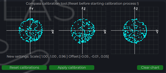
Figure: ULS-Tools Compass Calibration
Integration Verification in ULS-Tools
- Confirm live device telemetry is visible in charts.
- Verify stable IMU and system parameter traces before flight tests.
- Confirm receiver link and valid position updates prior to autopilot integration tests.
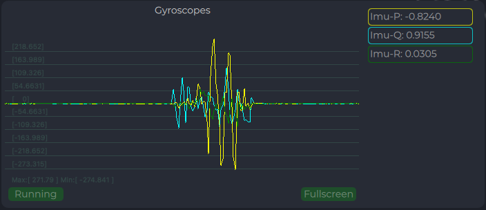
Figure: ULS-Tools System Parameters Chart
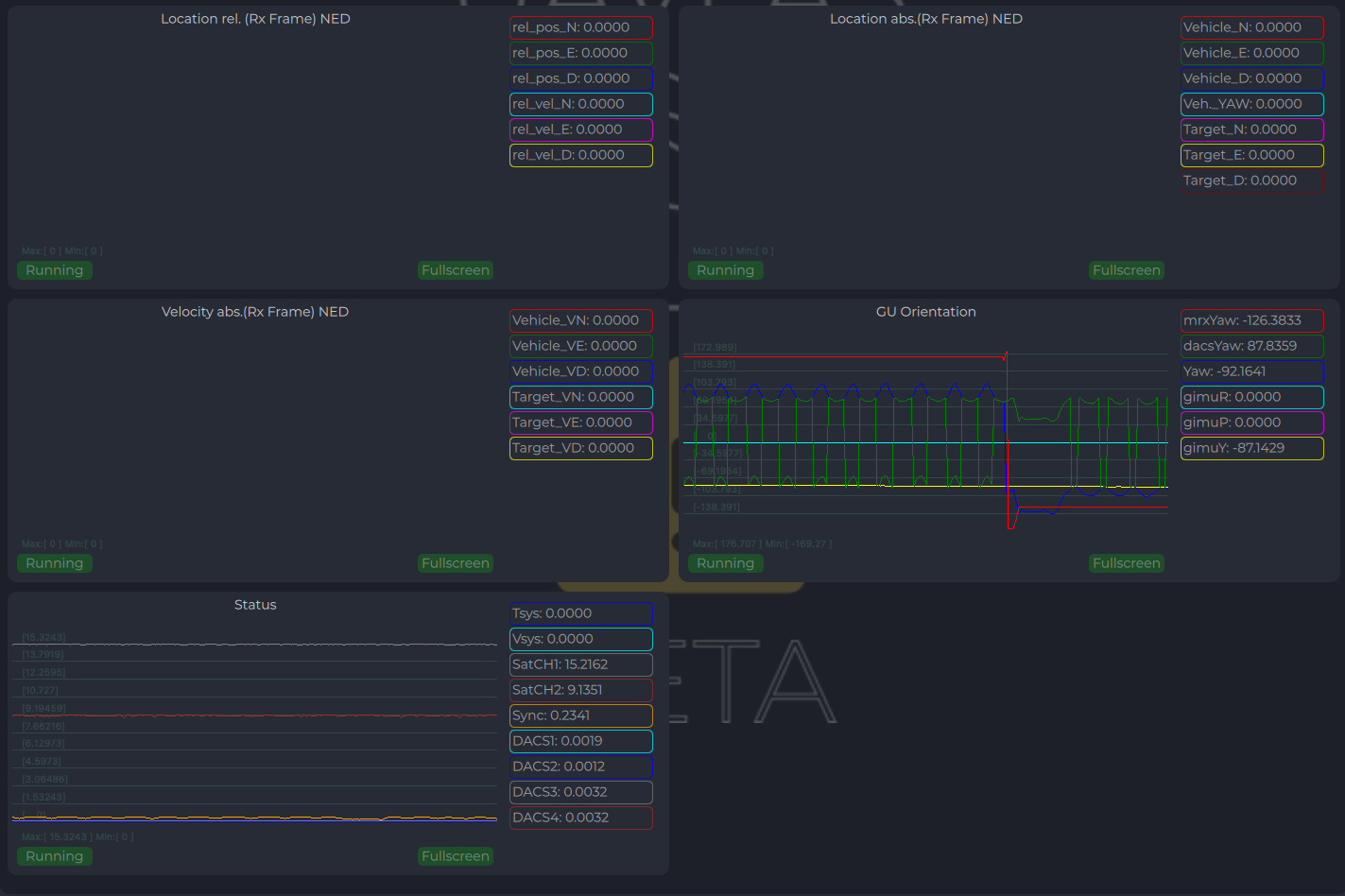
Figure: ULS-Tools Receiver Charts
Integration Instructions for Ardupilot Based Systems
Preparing for Integration
- Download the latest version of ULS-Tools (Beta). It is recommended to connect all devices to a PC and update firmware for all UAVLAS devices before proceeding.
- Update the autopilot to the latest Arducopter version.
- Configure the transmitter in ULS-Tools
- Configure both receivers in ULS-Tools
The system communicates with Ardupilot using the MavlinkV2 protocol (supports MAV_FRAME_BODY_FRD).
Autopilot Configuration
Setup PLND Section
| Param | Value | Comment |
|---|---|---|
| PLND_ENABLED | 1 | Enable the precision landing module |
| PLND_TYPE | 1 | Use type = 1 to enable UAVLAS sensor over the companion computer driver |
Table: Ardupilot PLND Section Parameters All other PLND parameters should remain at defaults, or be set according to your vehicle requirements.
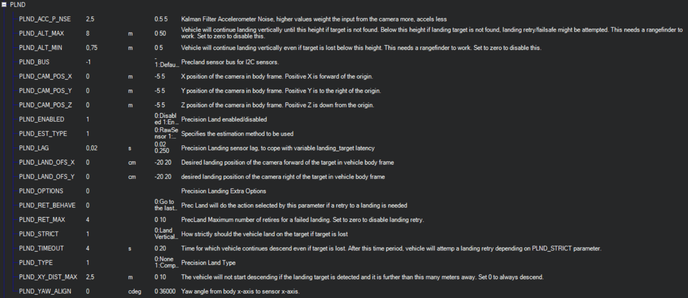
Figure: PLND Configuration Example
It is recommended to test several Kalman filter options during test flights (or switch it off) to achieve the best performance.
Set Up Serial Communication in SERIALx Section
| Param | Value | Comment |
|---|---|---|
| SERIAL2_BAUD | 230 | Baud rate — must match the receiver UART baud rate setting |
| SERIAL2_OPTIONS | 0 | Default |
| SERIAL2_PROTOCOL | 2 | MAVlink2 protocol |
Table: Ardupilot SERIALx Section Parameters Set up serial stream rates in the SRx section. The sensor requires the following data from the autopilot:
| Param | Value | Comment |
|---|---|---|
| SR2_EXTRA1 (or MAV2_EXTRA1) | 20 | Attitude stream at 20 Hz — required for compass mode yaw orientation |
| SR2_POSITION (or MAV2_POSITION) | 20 | Optional — Vehicle LOCAL_POSITION_NED stream at 20 Hz for absolute target position calculation |
Table: Ardupilot SRx Stream Rate Parameters
Check Setup
When configuration and wiring are correct, GPS is available, and the receiver is in the field of view of the transmitter, you will see the LANDING_TARGET MAVLink message in the MAVLink Inspector (Mission Planner example shown):
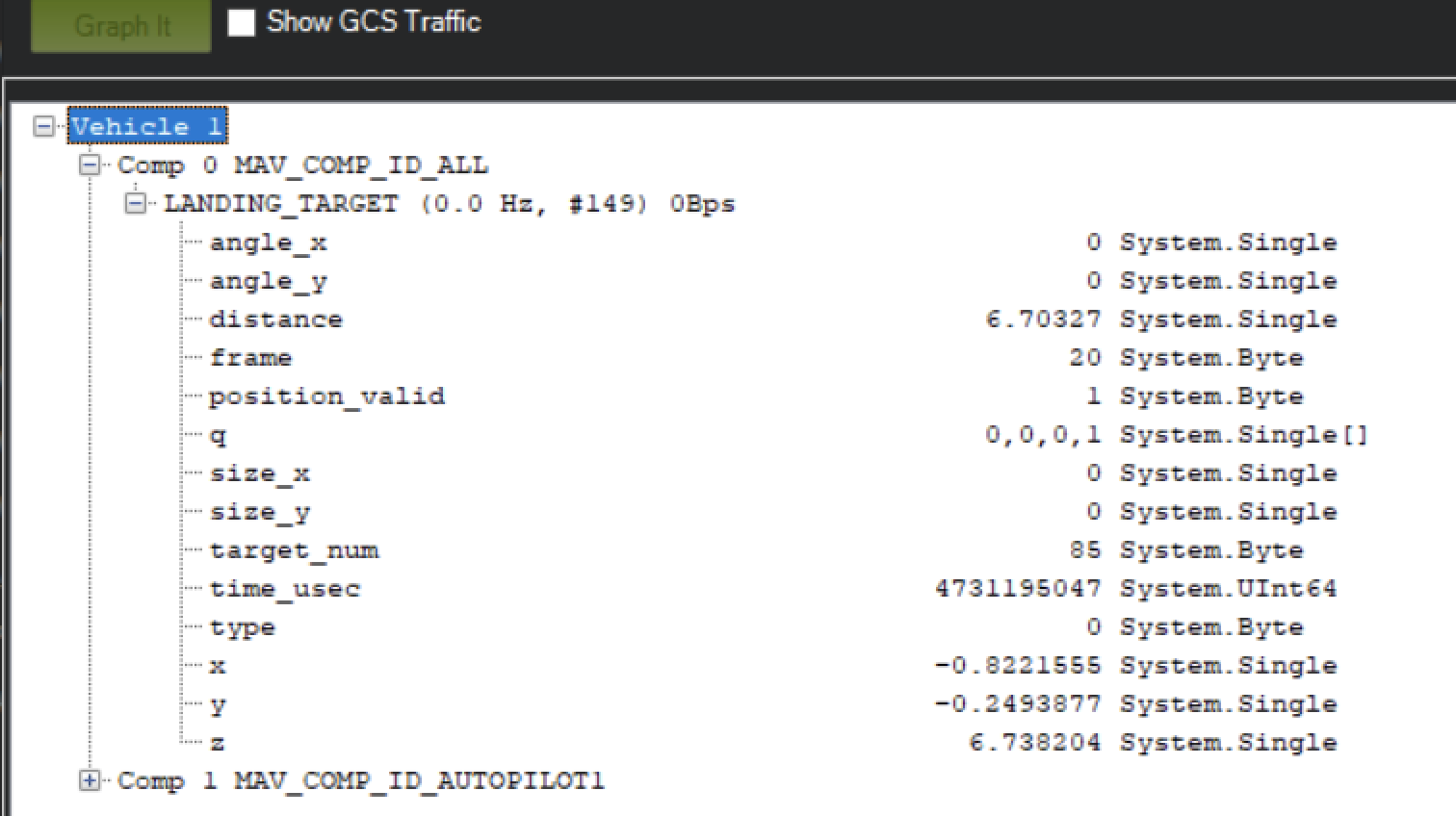
Figure: LANDING_TARGET Message in MAVLink Inspector
Setup Precision Loiter Mode
Attach any unused switch to the PrecLoiter option to enable precision loiter mode:
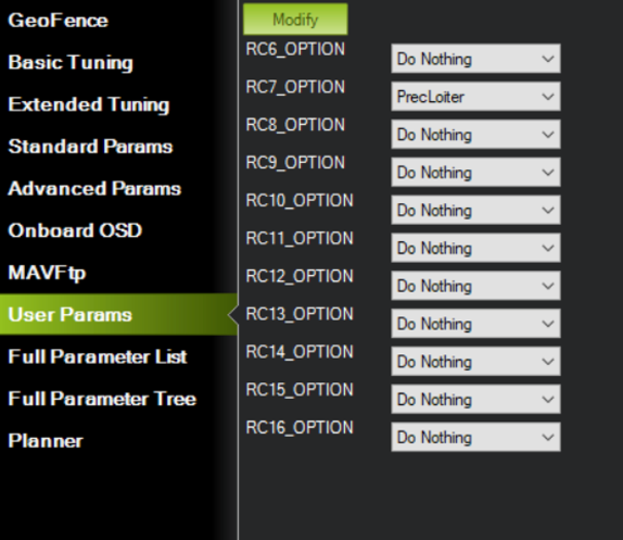
Figure: PrecLoiter Switch Configuration
Activate the switch and confirm messages “PrecLoiter: LOW” and “PrecLoiter: HIGH” appear. After a test flight above the target, check telemetry for PL offset data.
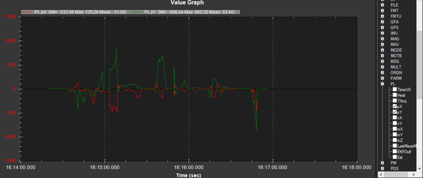
Figure: Telemetry Data Showing PL Offsets
PID Tuning
In case of oscillations or instability during landing, check the PID parameters in Ardupilot Extended Tuning.
It is recommended to tune Position XY, Velocity XY, and Loiter Speed for the best performance:
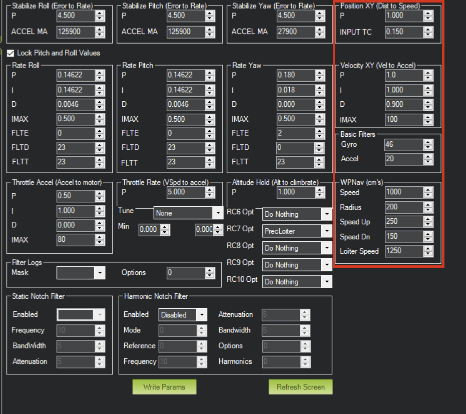
Figure: Ardupilot Extended Tuning Parameters
Settings of Velocity XY P = 0.8, I = 0.2, D = 0.6 have worked well for some customers as a starting point.
It is recommended to start PID testing and performance validation in Precision Loiter mode before enabling full precision landing.
For additional information, see the Ardupilot documentation at https://ardupilot.org/ardupilot/
Integration Instructions for PX4 Based Systems
Preparing for Integration
- Download the latest version of ULS-Tools (Beta). It is recommended to connect all devices to a PC and update firmware for all UAVLAS devices before proceeding.
- Update the autopilot to the latest PX4 version.
- Configure the transmitter in ULS-Tools.
- Configure both receivers in ULS-Tools.
The system communicates with PX4 using the MavlinkV2 protocol (supports MAV_FRAME_LOCAL_NED).
Configure PX4 Autopilot
Values are provided as an example (Pixhawk4-mini AP):
| PX4 Parameter | Value | Comment |
|---|---|---|
| MAV_1_CONFIG | TELEM/SERIAL4 | Requires reboot to apply the next parameters |
| MAV_1_FORWARD | Enabled | Forward MAVLink messages |
| MAV_1_MODE | Onboard | Set link mode to onboard |
| SER_TEL4_BAUD | 460800_8N1 | Must match the UART baud rate set in the receiver configuration |
Table: PX4 Autopilot Configuration Parameters
Running and Testing
After configuration and wiring, power up the drone and transmitter. In QGroundControl, go to Analyze Tools → MAVLink Inspector and check for the LANDING_TARGET MAVLink message.
If the vehicle is providing a LOCAL_POSITION_NED message to the UAVLAS system and is hovering over the beacon, the field position_valid = 1 will appear in LANDING_TARGET.
To perform precision landing, create a flight plan and enable the Precision Landing option on the landing waypoint.
LANDING_TARGET may be unavailable when connected over USB. Use a telemetry channel (UART modem, etc.) to connect the drone to QGroundControl during testing.
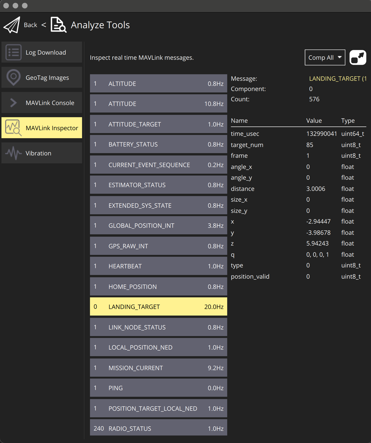
Figure: LANDING_TARGET Message in QGroundControl
For additional information, see the PX4 documentation at https://docs.px4.io/main/en/
Operating Instructions
- Power sequence: Power device after all connectors are plugged in before powering.
- Link check procedure: Link can be checked from the configuration system during system installation, as well as during operation using a third-party device via the appropriate protocols.
- Landing and approach operation notes: The vehicle’s control system independently decides on the appropriate action based on the status of the landing system. The UAVLAS system acts as a sensor—the procedure for handling abnormal situations during operation remains the responsibility of the unmanned vehicle’s control system.
- Equal-priority RXM behavior in MRX mode: Both receivers have the same priority, and either one can be used to receive system status data.
Service and Support
The device requires no maintenance throughout its service life.
Appendices
Technical Reference
| Parameter | Value |
|---|---|
| Distance range (m) | 30m…50m |
| Working angle (deg) | 60 |
| Data update frequency (Hz) | 20 |
| Receiver architecture | 2 identical RXM receivers with same priority |
| Redundancy mode | Dual-RXM redundancy |
| MRX yaw estimation method | Triangular method |
Table: Common Specification
| Parameter | Value |
|---|---|
| Field of view (deg) | 95 |
| Dimensions (mm) | 50x54 |
| Weight (g) | 50 |
| Power consumption (W) | 10 |
| Supply voltage (V) | +12V…+24V |
| Interfaces | CAN,USB,RS422 |
Table: ULSDV-HLXS-G3-RXM Receiver Specifications
| Parameter | Value |
|---|---|
| Field of emitting (deg) | 30 (60 in Wide Field) |
| Dimensions (mm) | 254 x 214 |
| Weight (g) | 1960 |
| Power consumption (W) | 20W |
| Supply voltage (V) | +18V..+24V |
| Interfaces | CAN, RS422 |
Table: ULSDV-HL-G3-TX Transmitter (Ground) Specifications
Change Control
All changes to this document must be reviewed and approved by the relevant technical leads and stakeholders
References
- ULSDC-PBDS110426-ULS-Heli-G3-Datasheet
- ULSDC-PBICD110426-ULS-Heli-G3-ICD
8 - ULS-OnNet
Production
8.1 - ULS-OnNet Datasheet
Datasheet ULSDC-PBDS061125, version 1.0.3
ULSDC-PBDS061125 · version 1.0.3 · issued August 14, 2026
The numbered PDF is the controlled copy: download it from the portal.
Introduction
Purpose
This datasheet provides a technical overview of the ULS-OnNet precision landing system: its role, architecture, performance figures, and integration characteristics. It is intended to let customers, evaluators, and integrators judge the fit of the system to a given fixed-wing platform and recovery method.
Scope
The document covers the ULS-OnNet-G2 system as delivered in its standard configuration: one ground transmitter (ULSDV-ON-TX-G2) and one onboard receiver (ULSDV-ON-RX-G2), with an optional second receiver for redundant operation. Detailed protocol and connector definitions are held in the interface documentation referenced at the end of this document.
Intended Audience
System engineers, integrators, autopilot developers, and technical evaluators preparing a ULS-OnNet installation on a fixed-wing platform or a recovery installation.
Product Overview
Description
ULS-OnNet is an optical (infrared) precision positioning system that gives a fixed-wing aircraft the navigation information required to perform an automatic precision landing into a recovery net or onto a tether. The system is aimed at small and medium fixed-wing UAVs and can also be used by small aircraft for conventional landing on the ground.
A single ground transmitter projects a structured infrared field along the approach direction. The onboard receiver decodes that field and outputs the position of the aircraft relative to the ground unit, at 20 Hz, to the autopilot. The autopilot remains fully responsible for aircraft control and for computing the landing path; ULS-OnNet supplies the relative navigation solution it needs.
The system does not use GNSS and does not use radio for the landing solution, so it continues to work where satellite navigation is jammed, degraded, or unavailable, and in areas where radio emission is undesirable.
Key Features
- 300 m operational range — flexible placement of the recovery installation while keeping precision guidance through the whole approach
- GNSS-independent operation — the landing solution relies only on the infrared field
- Infrared optical link at 940 nm — no radio emission, no radio interference, no spectrum coordination
- 0.8° accuracy in both the horizontal and vertical planes, with 0.1° resolution
- 20 Hz update rate — smooth, responsive approach control
- 24/7 operation across −40 °C to +85 °C and in harsh weather
- IP67 protection on all equipment against dust and water ingress
- Motion compensation — built-in level correction over a ±20° range for moving and shipborne platforms
- Simple integration — one transmitter on the ground, one receiver on board; a second receiver may be added for redundancy
- Lightweight onboard module — 85 g receiver, 47 × 26 × 17 mm
- Multi-protocol interfacing — CAN, RS422, and UART, with USB used for setup
- Fast start-up — the system is operational 2.8 s after power is applied
Advantages of the Optical Approach
Reduced susceptibility to interference. GNSS and radio signals can be disrupted by weather, terrain, or intentional jamming. By relying only on the infrared field, ULS-OnNet avoids these failure modes and keeps landings reliable in contested or difficult environments.
Increased safety in sensitive areas. Where radio emission could interfere with critical equipment — near hospitals, airports, or sensitive installations — an optical system is the safer alternative.
Weather-independent operation. The equipment holds its function across the full −40 °C to +85 °C range and under adverse weather, supporting mission continuity.
Motion compensation for moving platforms. The internal level correction system compensates platform movement over a 20° range, enabling recovery onto vessels experiencing wave motion up to moderate sea states.
Autonomous landing precision. 0.8° accuracy in both planes supports autonomous recovery without human intervention, reducing operational risk and the personnel required on site.
System Applications
- Net recovery of fixed-wing UAVs (spider-web style capture nets)
- Tether recovery with a wing-mounted hook
- Shipborne and other moving-platform recovery
- Landing guidance in GNSS-denied or GNSS-degraded environments
- Conventional ground/runway landing of small fixed-wing aircraft where high-precision guidance is required
- Research and development platforms for autonomous recovery
Supported Platforms
ULS-OnNet is optimised for fixed-wing platforms that require precision guidance into a net or tether recovery system.
| Platform class | MTOW | Typical use |
|---|---|---|
| Medium | 10 – 25 kg | Surveillance, reconnaissance, and commercial missions recovering onto maritime vessels and ground installations |
| Medium-large | 25 – 60 kg | Extended-range operations, cargo delivery, and professional applications recovering onto large vessels and specialised platforms |
Table: Supported Fixed-Wing Platform Classes Autopilot integration. Compatible with MAVLink-enabled autopilots across all supported weight categories. Custom integration protocols are available on request.
Landing Platform Compatibility
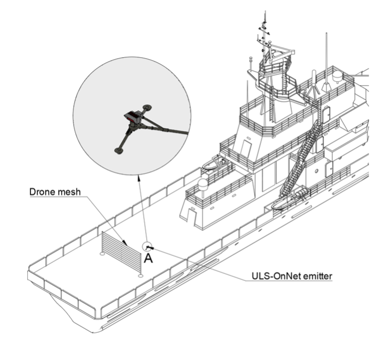
Figure: Landing on ship application
Net recovery systems. ULS-OnNet provides precision guidance for aircraft designed to land in recovery nets, holding an accurate approach vector under challenging conditions.
Tether-based platforms. Precision guidance onto tether systems, supporting reliable recovery for surveillance and monitoring missions.
Ground-based landing. Adaptable to conventional runway landing where high-precision guidance is required.
Maritime platforms. Designed to operate from moving vessels, compensating ship motion through the transmitter level correction system.
System Architecture
flowchart LR
  subgraph GND["Ground / Vessel Installation"]
    TX["ULSDV-ON-TX-G2 Transmitter\n• IR emission 940nm\n• 30° x 30° field\n• Level correction ±20°\n• 20-28V, 30W"]
    PC["Setup PC\n• USB\n• Configuration & diagnostics"]
  end
  subgraph AIR["Fixed-Wing Aircraft"]
    RX["ULSDV-ON-RX-G2 Receiver\n• IR sensor 940nm\n• 60° x 30° FOV\n• Relative position, 20Hz\n• 12-24V, 10W"]
    AP["Autopilot\n• MAVLink\n• CAN (ULS-Blitz)\n• Landing path control"]
  end
  TX -->|"Structured IR field, up to 300m"| RX
  PC -->|"Setup & diagnostics"| TX
  RX -->|"Relative position & status"| AP
The transmitter is the navigation beacon; the receiver is the navigation sensor. All positioning is computed on board from the received optical field, so the aircraft does not depend on a data link with the ground during the approach. Several aircraft can operate simultaneously inside the field of a single transmitter.
System Base Components
Receiver — Onboard Module (ULSDV-ON-RX-G2)
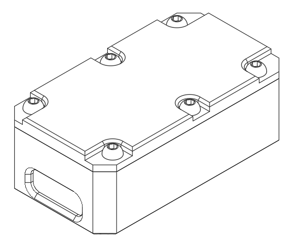
Figure: Onboard receiver (ULSDV-ON-RX-G2)
The onboard infrared receiver is the navigation sensor of the system. It captures the infrared signal from the ground transmitter and converts it into navigation data for the autopilot. Several receivers may be installed on one vehicle where redundant operation is required.
Key functions:
- IR signal reception — detects and decodes the 940 nm infrared navigation signal from the ground transmitter within the 300 m range
- Spatial processing — converts the received optical data into precise position and orientation information relative to the landing zone
- Autopilot interface — transmits processed navigation data to the autopilot over CAN or UART
- Real-time updates — continuous position output at 20 Hz for smooth approach guidance
- System integration — works with MAVLink and with custom autopilot solutions
Transmitter — Ground Module (ULSDV-ON-TX-G2)
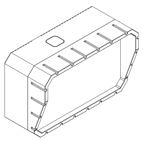
Figure: On-runway portable transmitter, 300 m (ULSDV-ON-TX-G2)
The ground-based infrared transmitter is the primary navigation beacon of the system. It projects a structured infrared field that provides spatial reference information to approaching aircraft within a 300 m operational range. It is mounted on the ground or on a vehicle or vessel.
Key functions:
- IR beacon generation — creates a precise infrared navigation field with 30° horizontal and vertical coverage
- Spatial reference — provides the position and orientation reference that makes accurate landing guidance possible
- Real-time status — transmits system status and diagnostic information to the onboard receiver
- Flexible operation — multiple vehicles can operate in the field of a single transmitter simultaneously
Part Numbering
| Part number | Item | Description |
|---|---|---|
| ULSDV-ON-TX-G2 | Transmitter | Ground/vehicle-mounted infrared transmitter, 300 m range |
| ULSDV-ON-RX-G2 | Receiver | Onboard infrared receiver module, 85 g |
Table: ULS-OnNet-G2 Device Part Numbers
The ULSDV-ON prefix identifies devices of the ULS-OnNet family; the -G2 suffix identifies the generation of the device.
Technical Specifications
General Specifications
| Parameter | Specification |
|---|---|
| Operation range | 300 m |
| Navigation method | Optical (infrared, 940 nm) |
| Radio wave independence | No GNSS or radio wave reliance for the landing solution |
| Optional connectivity | GNSS and radio connectivity available on request |
| Update rate | 20 Hz |
| Start-up time | 2.8 s |
| Landing capability | Nets, tethers, and ground |
Table: General System Specifications
Field of View
| Component | Horizontal | Vertical |
|---|---|---|
| Transmitter (emission field) | 30 degrees | 30 degrees |
| Receiver (sensor field) | 60 degrees | 30 degrees |
Table: Field of View Specifications
Accuracy
| Parameter | Specification |
|---|---|
| Horizontal accuracy | 0.8 degrees |
| Vertical accuracy | 0.8 degrees |
| Resolution (horizontal and vertical) | 0.1 degrees |
| Distance estimation accuracy | 2 m or 20 % of the distance, whichever is greater |
Table: System Accuracy and Resolution Angular accuracy is the primary specification of the system: the linear position error therefore grows in proportion to the distance from the transmitter, and the guidance becomes progressively tighter as the aircraft closes on the recovery point. Distance estimation is a coarser measurement than the angular solution and is intended to support approach staging, not touchdown geometry.
Power Requirements
| Unit | Supply | Consumption |
|---|---|---|
| Ground unit (ULSDV-ON-TX-G2) | 20 – 28 V DC, 3 A (battery or external supply) | 30 W |
| Onboard unit (ULSDV-ON-RX-G2) | 12 – 24 V DC, 1.2 A | 10 W |
Table: Power Supply and Consumption
Communication and Connectivity
| Parameter | Specification |
|---|---|
| Data connectivity | CAN, RS422, UART |
| Setup interface | USB |
| Communication protocols | MAVLink, ULS-Blitz over CAN; custom protocol solutions on request |
Table: Communication Interfaces and Connectivity Options
Transmitter Level Correction System
| Parameter | Specification |
|---|---|
| Level correction limit | 20 degrees |
| Level correction accuracy | 0.1 degrees |
Table: Transmitter Level Correction System Capabilities
Environmental Specifications
| Parameter | Range |
|---|---|
| Operating temperature range | −40 °C to +85 °C |
| IP rating | IP67 (dust-tight, protected against temporary immersion) |
Table: Environmental Operating Conditions and Protection Rating All ULS-OnNet equipment is sealed to IP67 and is intended for continuous outdoor and shipborne operation without additional weather protection. Qualification test data and certification documentation are available from UAVLAS on request.
Mechanical Specifications
Ground Unit (ULSDV-ON-TX-G2)
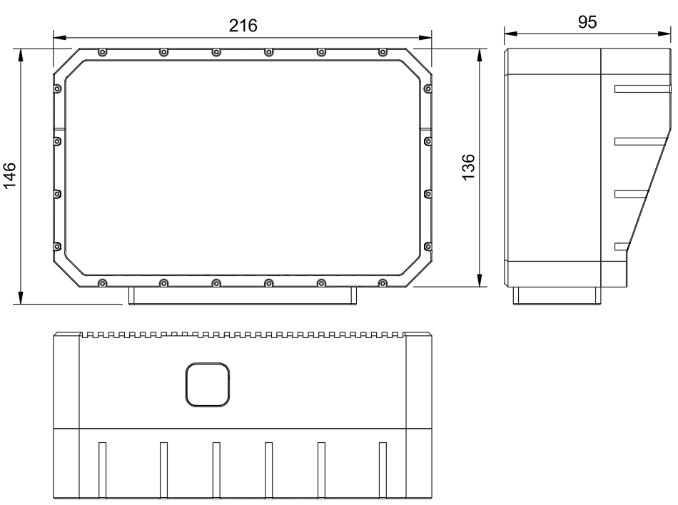
Figure: ULSDV-ON-TX-G2 dimensions
| Parameter | Specification |
|---|---|
| Dimensions | 213 × 136 × 95 mm |
| Weight | 3200 g |
Table: Transmitter Physical Specifications
Onboard Unit (ULSDV-ON-RX-G2)
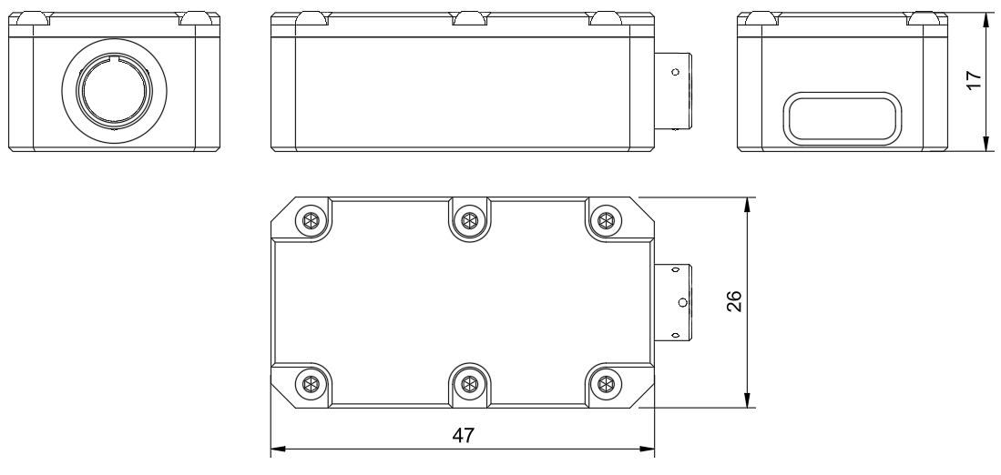
Figure: ULSDV-ON-RX-G2 dimensions
| Parameter | Specification |
|---|---|
| Dimensions | 47 × 26 × 17 mm |
| Weight | 85 g |
Table: Receiver Physical Specifications
Interface Summary
ULS-OnNet uses an optical link between the ground and the aircraft, and wired interfaces on each side of that link.
- Transmitter to receiver: optical infrared link, 940 nm, up to 300 m
- Transmitter to setup PC: USB, for configuration and diagnostics
- Receiver to autopilot: CAN or UART; RS422 and USB are available on the transmitter side
Transmitter Connector
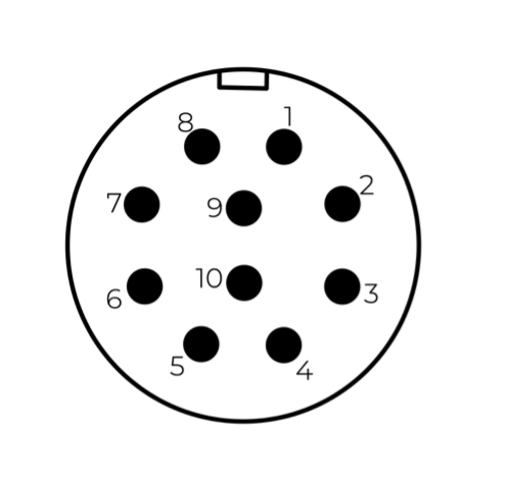
Figure: ULSDV-ON-TX-G2 connector pin numbers
| Pin | Function |
|---|---|
| 1 | Vin +18 V … +28 V |
| 2 | RS422A |
| 3 | RS422B |
| 4 | RS422Y |
| 5 | RS422Z |
| 6 | CAN-L |
| 7 | CAN-H |
| 8 | USB-D− |
| 9 | USB-D+ |
| 10 | GND |
Table: ULS-OnNet transmitter pinout
Do NOT "hot-plug" the transmitter cable. Apply power to the transmitter only when the connector is mated to the transmitter.
Check the pin numbers on the connector before wiring.
Incorrect wiring, or connection while under voltage, can damage the device and the USB interface of the connected PC.
Receiver Connector

Figure: ULSDV-ON-RX-G2 connector pin numbers
| Pin | Function |
|---|---|
| 1 | Vin (supply — see Power Requirements) |
| 2 | CAN-H |
| 3 | CAN-L |
| 4 | UART_TX (out) |
| 5 | UART_RX (in) |
| 6 | USB_D− |
| 7 | USB_D+ |
| 8 | GND |
Table: ULS-OnNet receiver pinout
Autopilot Integration
Integration Options
Standard protocol (MAVLink). The widely used open communication protocol for UAVs; integration with MAVLink-compatible autopilots is the simplest path.
CAN protocol (ULS-Blitz messages). Navigation data can be taken directly from the CAN bus using ULS-Blitz messages. See ULSDC-PBDS031025-ULS-Blitz-Types-and-Description.
Custom solution. UAVLAS can supply a custom integration where the autopilot does not support MAVLink or where specific functionality is required.
Data Provided by ULS-OnNet
Relative position. The onboard unit outputs the position of the aircraft relative to the ground transmitter, derived from the infrared navigation field.
System diagnostics. Transmitter level and life status are relayed to the onboard side.
Role of the Autopilot
Aircraft control. The autopilot remains responsible for flying the aircraft, including stability and manoeuvring during the approach.
Landing path calculation. The autopilot uses the relative position from ULS-OnNet to compute and fly a precise path into the net or onto the tether.
Installation
Ground Equipment
The ground segment of ULS-OnNet consists of a single main component and is straightforward to install.
Simplified setup. The transmitter is pointed along the intended landing path direction; no further alignment infrastructure is required.
Typical placement. The transmitter is ideally positioned behind the landing zone — behind the net or tether — for optimal signal geometry during the approach.
Fast start-up. The system becomes operational within 3 seconds of power being applied, which suits rapid deployment.
Levelling Requirements
Why levelling matters. A level transmitter installation maximises the usable radiation angle, and therefore the coverage area of the infrared field.
Level correction system. The built-in level correction system compensates minor mounting errors within a 20° range, at the cost of a slight reduction in the effective viewing angle.
Stabilised platform recommendation. For installation on objects with a high chance of tilting beyond 20° of roll, a stabilised platform is recommended to keep the transmitter level. UAVLAS offers customised solutions for such installations on request.
Onboard Equipment
Mounting. The receiver is mounted with a clear view along the approach direction, so that the transmitter stays inside the 60° × 30° sensor field through the whole approach.
Redundancy. A second receiver may be added and mounted so that the two units cover the approach independently.
Power and data. The receiver is supplied from the aircraft bus (12 – 24 V DC, 10 W) and connects to the autopilot over CAN or UART.
Packaging Information
ULS-OnNet-G2 is delivered as a complete precision landing solution containing everything needed for deployment: hardware modules, connectivity accessories, and documentation.
Standard Package Contents
| Component | Quantity | Part number | Description |
|---|---|---|---|
| Transmitter unit | 1 | ULSDV-ON-TX-G2 | Ground-based infrared transmitter, 300 m range |
| Receiver unit | 1 | ULSDV-ON-RX-G2 | Onboard infrared receiver module (85 g) |
| Transmitter cable | 1 | - | 10-pin connector cable for the transmitter |
| Receiver cable | 1 | - | 8-pin connector cable for the receiver |
| USB configuration cable | 2 | - | For system setup and diagnostics |
| Mounting hardware | 1 set | - | Brackets and screws for installation |
| Quick start guide | 1 | - | Initial setup instructions |
| Technical documentation | 1 set | - | Complete system manuals and specifications |
Table: ULS-OnNet-G2 Standard Package Contents
Optional Accessories
| Component | Part number | Description |
|---|---|---|
| Secondary receiver | ULSDV-ON-RX-G2 | Additional receiver for redundant operation |
| Extended cable kit | - | Longer cables for specific installation requirements |
| Power supply unit | - | Dedicated power supply for the ground transmitter |
Table: Optional Accessories
Optical Radiation Safety (IR Emission)
The transmitter (ground unit) emits pulsed infrared optical radiation with a centre wavelength of 940nm. The receivers are optical sensors only and do not emit optical radiation.
INFRARED RADIATION IS EMITTED FROM THE TRANSMITTER OPTICAL APERTURES WHENEVER THE UNIT IS POWERED. Do not look into the transmitter emitter apertures at close range. IR emission at 940nm is invisible and does not trigger the blink or aversion reflex, so the eye receives no natural warning of exposure.
Why This Warning Is Given
Radiation at 940nm is outside the visible range. The protective mechanisms that limit exposure to bright visible sources — the blink reflex, pupil constriction, and the instinct to look away — are not triggered by an invisible source. Exposure time is therefore limited only by operator behaviour, which is why the precautions below are given as operating instructions and not left to the operator’s judgement.
The transmitter is a positioning beacon. It is not an illumination product and is not intended to be viewed at any time.
Operating Precautions
- Do not look directly into the transmitter emitter apertures from a distance of less than 1 metre while the unit is powered.
- Treat the transmitter as emitting whenever supply voltage is applied, including when no receiver is present and no positioning data is being transferred.
- Switch emission off before working directly in front of the transmitter. Use the Illumination parameter in ULS-Tools to disable emission, or disconnect supply power.
- Do not view the powered transmitter through binoculars, telescopes, camera lenses, magnifiers, or any other light-collecting instrument. Such optics concentrate the emission and can raise the exposure at the eye by orders of magnitude compared with unaided viewing.
- Do not add, remove, or modify optical elements of the transmitter. Added optics change the emission characteristics and invalidate any photobiological classification of the unit.
- Position the transmitter so that the emission field is directed away from work positions and walkways where personnel stay for extended periods.
- Servicing personnel working inside the emission field at close range should disable emission first rather than rely on viewing distance.
Classification and Applicable Standards
| Item | Value |
|---|---|
| Emitter type | Incoherent IR LED array (not a laser) |
| Centre wavelength | 940nm |
| Emission mode | Pulsed |
| Applicable standard | IEC 62471 / EN 62471, Photobiological safety of lamps and lamp systems |
| Classification distance | 200mm (non-GLS source, per IEC 62471) |
| Risk group | TBD — to be entered from the IEC 62471 assessment report |
| Hazard distance | TBD — to be entered from the IEC 62471 assessment report |
Table: Optical Radiation Safety Data
The transmitter uses light emitting diodes, not laser emitters. LED sources are assessed under IEC 62471; the laser product standard IEC 60825-1 does not apply to this product.
For a 940nm source the applicable exposure limits are the retinal thermal hazard (380nm to 1400nm), the retinal thermal hazard for a weak visual stimulus (780nm to 1400nm, which applies specifically to sources that give no visual cue), and the infrared hazard to the cornea and lens (780nm to 3000nm). The corneal and lens limits are intended for chronic exposures longer than 1000s at a daily averaged irradiance of 100 W/m² or more.
Organisations operating this equipment within the European Union are additionally subject to Directive 2006/25/EC on the exposure of workers to artificial optical radiation, which requires the employer to assess worker exposure against the exposure limit values given in Annex I of that directive. UAVLAS provides the emission data needed for that assessment on request.
Compliance and Standards
- RoHS compliant
- Document classification and release control as defined in the document metadata
- Product-specific compliance statements to be finalised for release
Ordering Information
Use the part numbering and packaging sections to identify system variants, subassemblies, and accessories. Communication protocol selection is agreed per installation; optional GNSS and radio connectivity can be supplied for preliminary calculation of the landing slope.
Change Control
All changes to this document must be reviewed and approved by the relevant technical leads and stakeholders
References
- ULSDC-PBDS031025-ULS-Blitz-Types-and-Description
9 - ULS-ProCopter
Production
9.1 - ULS-ProCopter Datasheet
Datasheet ULSDC-PBDS070425, version 1.0.0
ULSDC-PBDS070425 · version 1.0.0 · issued June 14, 2025
The numbered PDF is the controlled copy: download it from the portal.
Introduction
Purpose
The purpose of this datasheet is to provide comprehensive technical information about the ULS-ProCopter System family. This includes specifications, performance characteristics, and detailed descriptions of system components, such as transmitters and receivers. By outlining the interfaces between these components, the datasheet aims to facilitate seamless integration and operation for system engineers, integrators, and developers working with ULS-ProCopter systems.
Scope
This document is intended for use by system engineers, integrators, and developers working with ULS-ProCopter systems. It provides detailed information on the system.
System Base Components
Transmitter (Ground Unit)
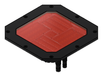
Figure: ULS-ProCopter Transmitter
A transmitter is a device placed on the ground (platform, moving object). It emits a signal in the Infrared range and serves as a kind of beacon. Transmitter marks position for drone landing.
The primary function of the transmitter is to continuously send out a coded signal that can be detected and interpreted by the receiver unit onboard the ULS-ProCopter. This signal contains critical information needed for the operation of the ULS-ProCopter, such as positional data, commands, and system status.
Receiver (Onboard Unit)
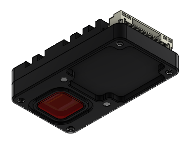
Figure: ULS-ProCopter Receiver
A receiver is a device that is placed on board an aircraft.
The receiver decodes this signal to derive flight information such as positional coordinates, real-time transmitter status updates, and landing guidance. It interprets the data to navigate accurately and ensure drone follows the intended flight path. It provides feedback to the autopilot systems, such as Ardupilot and PX4, to adjust the flight parameters as needed for optimal and safety landing or hovering above.
Part Numbering
| Part Number | Description |
|---|---|
| ULS-ProCopter | System set with 1 receiver. |
| ULS-ProCopter-MRX | System set with 2 receivers. |
| ULSDV-PC-TX | Transmitter unit. Generation 2. |
| ULSDV-PC-RX | Receiver unit. Generation 2. |
| GHR-10V-S | 10 Pin Connector for receiver. Cable side. Manufacturer, JST Commercial. |
| SA810/P8IIB | 8 Pin Connector for transmitter. Cable side. Manufacturer, Weipu Connector. |
| SA610/P4IB | 4 Pin Connector for transmitter. Cable side. Manufacturer, Weipu Connector. |
Table: ULS-ProCopter Part Numbers and Descriptions
System specification.
Common specification:
| Parameter | Value |
|---|---|
| Distance range m.: | 0.1 - 20.0 |
| Working angle (deg): | >100 |
| Data update frequency (Hz): | 20 |
Table: Common System Specifications Receiver (on board unit):
| Parameter | Value |
|---|---|
| Field of view (deg): | 100 |
| Dimensions mm : | 18.4 x 33.4 x 6.9 |
| Weight g.: | 10 |
| Power Consumption (W): | 0.3 |
| Voltage supply (V): | 5.0 |
| Interfaces: | USB, CAN, UART |
Table: Receiver Specifications Transmitter (on ground)
| Parameter | Value |
|---|---|
| Field of emitting (deg): | >100 |
| Dimensions mm. : | 183 x 183 x 29 |
| Weight g.: | 1200 |
| Power Consumption (W): | 18.4 |
| Voltage supply (V): | 12V- 27V |
| Interfaces : | USB, CAN, UART |
Table: Transmitter Specifications
Pinout information
Transmitter pinout
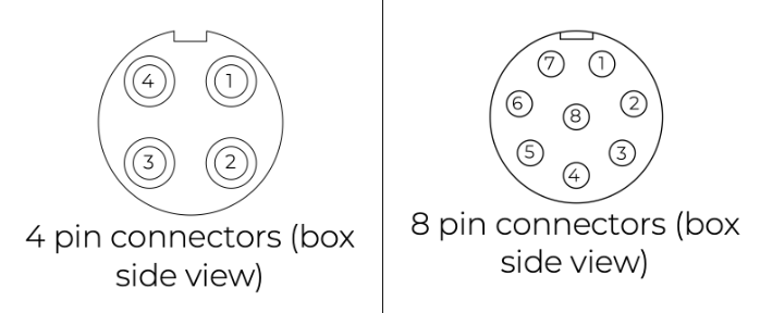
Figure: ULS-ProCopter Transmitter Pinout Diagram
| Pin number | ProCopter |
|---|---|
| 1 | Vcc Input (+12.0V..+27V) |
| 2 | CAN2 H |
| 3 | CAN2 L |
| 4 | UART TX |
| 5 | UART RX |
| 6 | USB D- |
| 7 | USB D+ |
| 8 | GND |
Table: Transmitter 8-pin Main Connector Pinout
| Pin number | ProCopter |
|---|---|
| 1 | +5V Output |
| 2 | CAN1 H |
| 3 | CAN1 L |
| 5 | GND |
Table: Transmitter 4-pin Connector Pinout
Please DO NOT "HOT-PLUG" Transmitter cable. Apply power on transmitter only when connector connected to transmitter.
Please check pin numbers on connector.
Incorrect wiring or connection under voltage can damage the device and USB interface of connected PC !
Receiver pinout
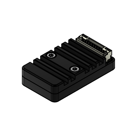
Figure: Receiver Top Side Connector Variant
Figure: Receiver Strait Variant
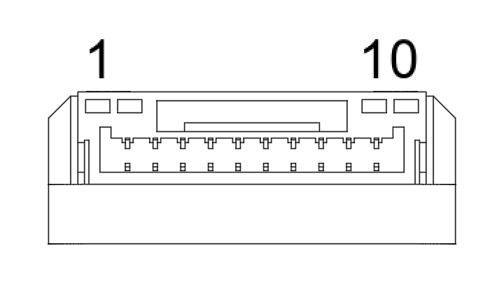
Figure: ULS-ProCopter Receiver connector
| Pin number | Strait Variant | Top Side Connector Variant |
|---|---|---|
| 1 | +5V Input | GND |
| 2 | UART RX | UART2 TX |
| 3 | UART TX | UART2 RX |
| 4 | CAN H | USB D+ |
| 5 | CAN L | USB D- |
| 6 | USB D- | CAN L |
| 7 | USB D+ | CAN H |
| 8 | UART2 RX | UART TX |
| 9 | UART2 TX | UART RX |
| 10 | GND | +5V Input |
Table: Receiver JX1 Connector Pinout (External Power and Control)
Mechanical dimensions
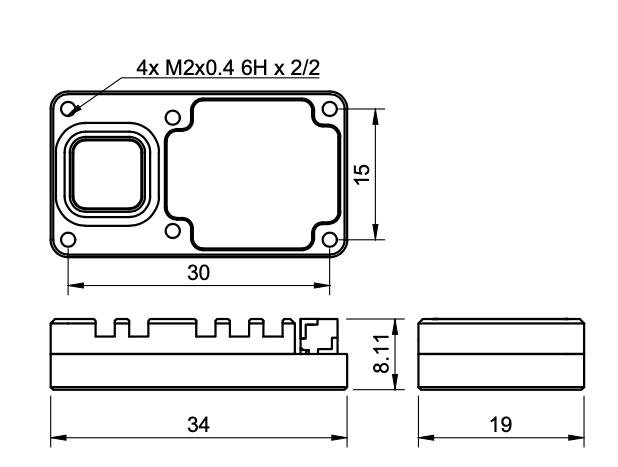
Figure: ULS-ProCopter Receiver dimensions
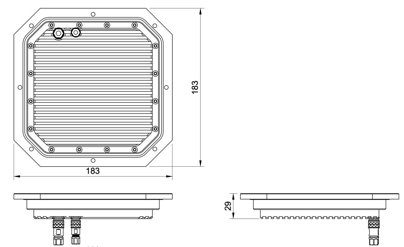
Figure: ULS-ProCopter Transmitter Mechanical Dimensions
System performance characteristics
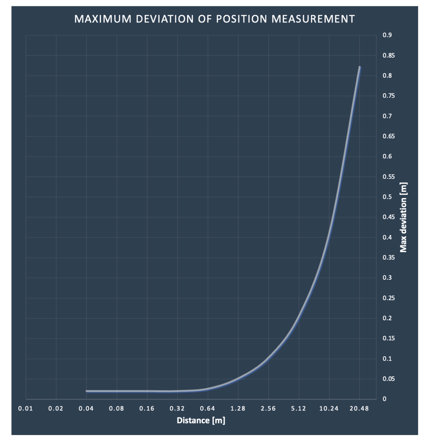
Environmental Conditions - Industrial Grade
Equipment is designed to operate reliably in demanding environmental conditions typical of aerospace, industrial automation, and outdoor applications.
Operating Temperature Range
- Standard operating range: -20°C to +55°C
- Covers most industrial and outdoor applications
- Reliable performance across temperature extremes
- No performance degradation within specified range
Humidity Tolerance
- Relative humidity: Up to 70% (non-condensing)
- Protected against moisture in typical operating conditions
- Suitable for outdoor and semi-protected installations
- Condensation prevention through sealed design
Ingress Protection
- IP67 rated (Dust tight and water immersion resistant)
- 6 - Complete protection against dust ingress
- 7 - Protected against temporary immersion in water (up to 1 meter depth for 30 minutes)
- Suitable for harsh industrial environments
- Protected against rain, splashing, and temporary submersion
- Dust-tight sealing for contaminated environments
Storage Conditions
- Storage temperature: -40°C to +70°C
- Relative humidity: Up to 95% (non-condensing)
- Long-term storage in industrial facilities
Operational Environment Standards
- Designed to meet industrial equipment requirements
- Suitable for UAV/drone applications
- Outdoor installation capable
- Protected against:
- Dust and particulate matter
- Water spray and rain
- Temporary water immersion
- Temperature fluctuations
- High humidity
Dust and moisture protection: Not applicable to the ULSDV-PC-RX, protective measures are required against dust and moisture.
Change Control
All changes to this document must be reviewed and approved by the relevant technical leads and stakeholders
9.2 - ULS-ProCopter Interface Control Document
Interface Control Document ULSDC-PBICD070425, version 1.0.0
ULSDC-PBICD070425 · version 1.0.0 · issued June 10, 2025
The numbered PDF is the controlled copy: download it from the portal.
Introduction
Purpose
This document outlines the interfaces between the ULS-ProCopter system components, including the transmitter, receiver, and autopilot systems (Ardupilot and PX4 and similar).
Scope
This document is intended for use by system engineers, integrators, and developers working with ULS-ProCopter systems. It provides detailed information on the interfaces between the system components, ensuring seamless integration and operation.
System Components
Transmitter (Ground Unit)
Figure: ULS-ProCopter Transmitter
A transmitter is a device placed on the ground (platform, moving object). It emits a signal in the Infrared range and serves as a kind of beacon. Transmitter marks position for drone landing.
The primary function of the transmitter is to continuously send out a coded signal that can be detected and interpreted by the receiver unit onboard the ULS-ProCopter. This signal contains critical information needed for the operation of the ULS-ProCopter, such as positional data, commands, and system status.
Receiver (Onboard Unit)
Figure: ULS-ProCopter Receiver
A receiver is a device that is placed on board an aircraft.
The receiver decodes this signal to derive flight information such as positional coordinates, real-time transmitter status updates, and landing guidance. It interprets the data to navigate accurately and ensure drone follows the intended flight path. It provides feedback to the autopilot systems, such as Ardupilot and PX4, to adjust the flight parameters as needed for optimal and safety landing or hovering above.
Interface Overview
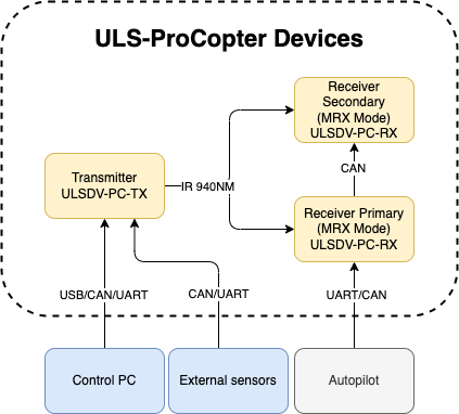
Figure: ULS-ProCopter System Interface Overview
Transmitter to control PC interface (external sensors):
Data Type:
- Status information
- Control signals
- Transmitter configuration
- External IMU/COMPASS data
Connection Types
- CAN Bus - For network communication
- USB - For configuration and firmware updates
- UART - For serial communication with external sensors
Pinout:
Figure: ULS-ProCopter Transmitter Pinout Diagram
| Pin number | ProCopter |
|---|---|
| 1 | Vcc Input (+12.0V..+27V) |
| 2 | CAN2 H |
| 3 | CAN2 L |
| 4 | UART TX |
| 5 | UART RX |
| 6 | USB D- |
| 7 | USB D+ |
| 8 | GND |
Table: Transmitter 8-pin Main Connector Pinout
| Pin number | ProCopter |
|---|---|
| 1 | +5V Output |
| 2 | CAN1 H |
| 3 | CAN1 L |
| 5 | GND |
Table: Transmitter 4-pin Connector Pinout
Please DO NOT "HOT-PLUG" Transmitter cable. Apply power on transmitter only when connector connected to transmitter.
Please check pin numbers on connector.
Incorrect wiring or connection under voltage can damage the device and USB interface of connected PC !
Transmitter to Receiver Interface:
The transmitter and receiver use an optical interface to exchange data. Transmission use IR emission 940 nanometers. Data transmission is only in the direction from the transmitter to the receiver.
Data Type:
- Position encoded
- Status encoded data (Transmitter orientation and instructions)
Connection Type
- Optical IR 940nm - Infrared optical link
Receiver to Autopilot and Receiver to PC Interfaces
Data Type:
- Mavlink messages
- ULS-Blitz frames
- ASCII protocol
Connection Types
- UART - Serial communication with autopilot
- CAN - Network communication
- USB - Direct PC connection
Pinout:
Figure: Receiver Top Side Connector Variant
Figure: Receiver Strait Variant
Figure: ULS-ProCopter Receiver connector
| Pin number | Strait Variant | Top Side Connector Variant |
|---|---|---|
| 1 | +5V Input | GND |
| 2 | UART RX | UART2 TX |
| 3 | UART TX | UART2 RX |
| 4 | CAN H | USB D+ |
| 5 | CAN L | USB D- |
| 6 | USB D- | CAN L |
| 7 | USB D+ | CAN H |
| 8 | UART2 RX | UART TX |
| 9 | UART2 TX | UART RX |
| 10 | GND | +5V Input |
Table: Receiver JX1 Connector Pinout (External Power and Control)
Powering Interfaces
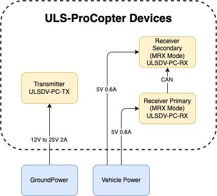
Figure: ULS-ProCopter Powering Interfaces and Electrical Characteristics
Transmitter Electrical Characteristics
- Supply Voltage: 12.0V - 25V
- Supply Current: 2A
- Power Consumption: 18.1 W
Receiver Electrical Characteristics
- Supply Voltage: 5.0V
- Supply Current: 0.6A
- Power Consumption: 3 W
Functional Interfaces

Figure: ULS-ProCopter Functional Interfaces and Data Flow
Data Exchange
- Control PC used to configure and view status of transmitter.
- Control PC used to set configuration of receivers.
- Control PC (or embedded equipment instead control pc) can be used to send control signals (On/off, compass override information)
- External IMU/Compass equipment can be used to override internal IMU/compass information.
- Receiver accept data from transmitter over IR signal. This data include position field information and ground unit IMU data.
- Receiver accept NED and Attitude information from autopilot to be able convert coordinate system that can be accepted by autopilot.
- Several Receivers can communicate to be able calculate vehicle orientation YAW.
- Receiver send position offset data to autopilot.
Mechanical interfaces
Transmitter mechanical interface:
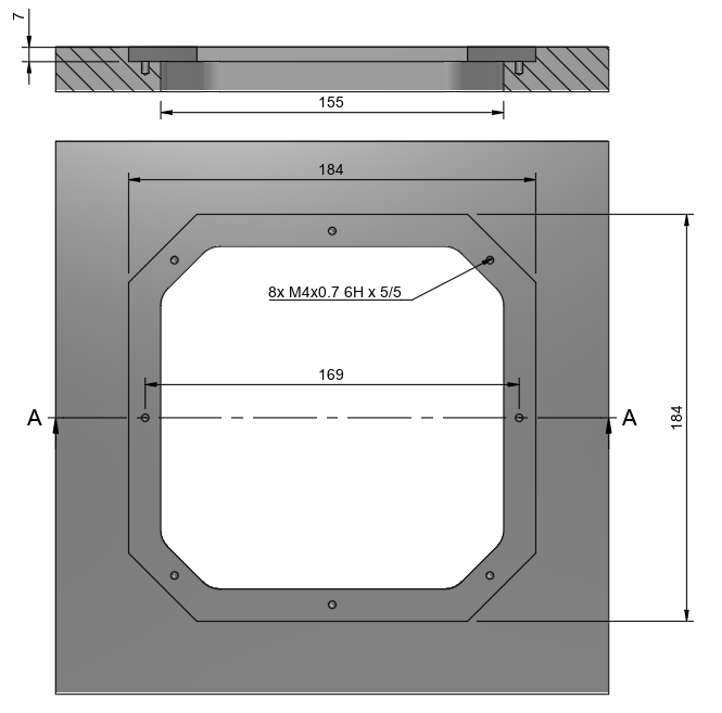
Figure: ULS-ProCopter Transmitter Mechanical Interface and Mounting Dimensions
Receiver mechanical interface:
Figure: ULS-ProCopter Receiver Mechanical Interface and Mounting Dimensions
Environmental Conditions - Industrial Grade
Equipment is designed to operate reliably in demanding environmental conditions typical of aerospace, industrial automation, and outdoor applications.
Operating Temperature Range
- Standard operating range: -20°C to +55°C
- Covers most industrial and outdoor applications
- Reliable performance across temperature extremes
- No performance degradation within specified range
Humidity Tolerance
- Relative humidity: Up to 70% (non-condensing)
- Protected against moisture in typical operating conditions
- Suitable for outdoor and semi-protected installations
- Condensation prevention through sealed design
Ingress Protection
- IP67 rated (Dust tight and water immersion resistant)
- 6 - Complete protection against dust ingress
- 7 - Protected against temporary immersion in water (up to 1 meter depth for 30 minutes)
- Suitable for harsh industrial environments
- Protected against rain, splashing, and temporary submersion
- Dust-tight sealing for contaminated environments
Storage Conditions
- Storage temperature: -40°C to +70°C
- Relative humidity: Up to 95% (non-condensing)
- Long-term storage in industrial facilities
Operational Environment Standards
- Designed to meet industrial equipment requirements
- Suitable for UAV/drone applications
- Outdoor installation capable
- Protected against:
- Dust and particulate matter
- Water spray and rain
- Temporary water immersion
- Temperature fluctuations
- High humidity
Dust and moisture protection: Not applicable to the ULSDV-PC-RX, protective measures are required against dust and moisture.
Change Control
All changes to this document must be reviewed and approved by the relevant technical leads and stakeholders
9.3 - ULS-ProCopter Operation Manual
Operation Manual ULSDC-PBOM070425, version 1.0.0
ULSDC-PBOM070425 · version 1.0.0 · issued June 14, 2025
The numbered PDF is the controlled copy: download it from the portal.
Introduction
Purpose
The purpose of this operation manual is to provide comprehensive guidance on the installation, configuration, operation, and troubleshooting of the ULS-ProCopter System. This manual is designed to help users effectively integrate and utilize the system for precision landing and navigation applications.
Scope
This document is intended for use by system engineers, integrators, operators, and developers working with ULS-ProCopter systems. It provides detailed information on system operation, configuration procedures, and integration with autopilot systems.
System Base Components
Transmitter (Ground Unit)
Figure: ULS-ProCopter Transmitter
A transmitter is a device placed on the ground (platform, moving object). It emits a signal in the Infrared range and serves as a kind of beacon. Transmitter marks position for drone landing.
The primary function of the transmitter is to continuously send out a coded signal that can be detected and interpreted by the receiver unit onboard the ULS-ProCopter. This signal contains critical information needed for the operation of the ULS-ProCopter, such as positional data, commands, and system status.
Receiver (Onboard Unit)
Figure: ULS-ProCopter Receiver
A receiver is a device that is placed on board an aircraft.
The receiver decodes this signal to derive flight information such as positional coordinates, real-time transmitter status updates, and landing guidance. It interprets the data to navigate accurately and ensure drone follows the intended flight path. It provides feedback to the autopilot systems, such as Ardupilot and PX4, to adjust the flight parameters as needed for optimal and safety landing or hovering above.
Operation theory
All data communication from the transmitter to the receiver is done in the optical band, which eliminates interference with other radio devices and radio signals.
The transmitter contains an array of emitting elements that operate in the infrared range. The transmitter emits a modulated signal with each of the transmitter emitters transmitting a unique signal. Each of the transmitter emitters emits in a unique direction. The receiver receives the signal from the transmitter decodes it and by analyzing the signal can determine in which direction relative to the transmitter it is located. The distance to the transmitter is determined by the signal strength. Thus the system determines the position in a polar coordinate system with the origin at the center of the transmitter.
It is worth noting that due to the features described above, the receiver position readings will change when the transmitter orientation is changed, but the change in receiver orientation will have no effect if the transmitter and receiver are within the range of visibility of the systems specified in the specification.
This must be taken into account when working with the system. In order to calculate the position of the receiver without errors in case of orientation changes, the transmitter is equipped with an inertial orientation measurement system. This system allows you to determine the orientation of the module and transmit this information to the receiver by means of an infrared signal so that it can correct the position according to the inclination of the transmitter (transmitter level correction function).
The system can then convert the polar coordinate system to a Cartesian coordinate system. In this case, this coordinate system originates at the center of the transmitter.
Usually, to navigate and ensure a precise landing, the autopilot needs information about the position of the landing point in a coordinate system either attached to the drone’s body or in a global coordinate system.
The system can then convert the polar coordinate system to a Cartesian coordinate system. In this case, this coordinate system originates at the center of the transmitter.
To navigate and ensure a precise landing, the autopilot needs information about the position of the landing point in a coordinate system either attached to the drone’s body or in a global coordinate system. For this purpose, the receiver requests information from the autopilot about its position and orientation. Then, using this information and information about the orientation of the ground transmitter, the receiver can calculate the position of the transmitter relative to the drone in the required coordinates.
It important to point out that the system will act as a navigation sensor. The information from our system can be used by autopilots and drones for various purposes:
- Landing vehicle on platform
- Hovering over a point of interest
- Accurately dropping a load or precisely lowering it on a tether.
Functional description diagram
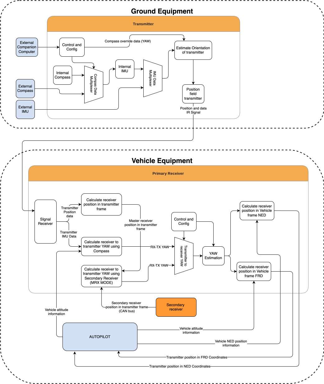
System specification.
Common specification:
| Parameter | Value |
|---|---|
| Distance range m.: | 0.1 - 20.0 |
| Working angle (deg): | >100 |
| Data update frequency (Hz): | 20 |
Table: Common System Specifications Receiver (on board unit):
| Parameter | Value |
|---|---|
| Field of view (deg): | 100 |
| Dimensions mm : | 18.4 x 33.4 x 6.9 |
| Weight g.: | 10 |
| Power Consumption (W): | 0.3 |
| Voltage supply (V): | 5.0 |
| Interfaces: | USB, CAN, UART |
Table: Receiver Specifications Transmitter (on ground)
| Parameter | Value |
|---|---|
| Field of emitting (deg): | >100 |
| Dimensions mm. : | 183 x 183 x 29 |
| Weight g.: | 1200 |
| Power Consumption (W): | 18.4 |
| Voltage supply (V): | 12V- 27V |
| Interfaces : | USB, CAN, UART |
Table: Transmitter Specifications
Pinout information
Transmitter Pinout
Figure: ULS-ProCopter Transmitter Pinout Diagram
| Pin number | ProCopter |
|---|---|
| 1 | Vcc Input (+12.0V..+27V) |
| 2 | CAN2 H |
| 3 | CAN2 L |
| 4 | UART TX |
| 5 | UART RX |
| 6 | USB D- |
| 7 | USB D+ |
| 8 | GND |
Table: Transmitter 8-pin Main Connector Pinout
| Pin number | ProCopter |
|---|---|
| 1 | +5V Output |
| 2 | CAN1 H |
| 3 | CAN1 L |
| 5 | GND |
Table: Transmitter 4-pin Connector Pinout
Please DO NOT "HOT-PLUG" Transmitter cable. Apply power on transmitter only when connector connected to transmitter.
Please check pin numbers on connector.
Incorrect wiring or connection under voltage can damage the device and USB interface of connected PC !
Receiver Pinout
Figure: Receiver Top Side Connector Variant
Figure: Receiver Strait Variant
Figure: ULS-ProCopter Receiver connector
| Pin number | Strait Variant | Top Side Connector Variant |
|---|---|---|
| 1 | +5V Input | GND |
| 2 | UART RX | UART2 TX |
| 3 | UART TX | UART2 RX |
| 4 | CAN H | USB D+ |
| 5 | CAN L | USB D- |
| 6 | USB D- | CAN L |
| 7 | USB D+ | CAN H |
| 8 | UART2 RX | UART TX |
| 9 | UART2 TX | UART RX |
| 10 | GND | +5V Input |
Table: Receiver JX1 Connector Pinout (External Power and Control)
Mechanical dimensions
Figure: ULS-ProCopter Receiver dimensions
Figure: ULS-ProCopter Transmitter Mechanical Dimensions
Integration
Ground unit installation (transmitter)
The device must be installed on a clean surface to avoid any obstacles. The device must be installed in an open area. There must be no obstacles in the radiation field of the transmitting device. If possible, avoid installing the system near vertical surfaces that can strongly reflect infrared radiation. Device developed to be installed in panel and bolted with M4 screw. All customers get 3d model of system and cut panel as reference to make integration process more simple.
Panel cut-out drawing.
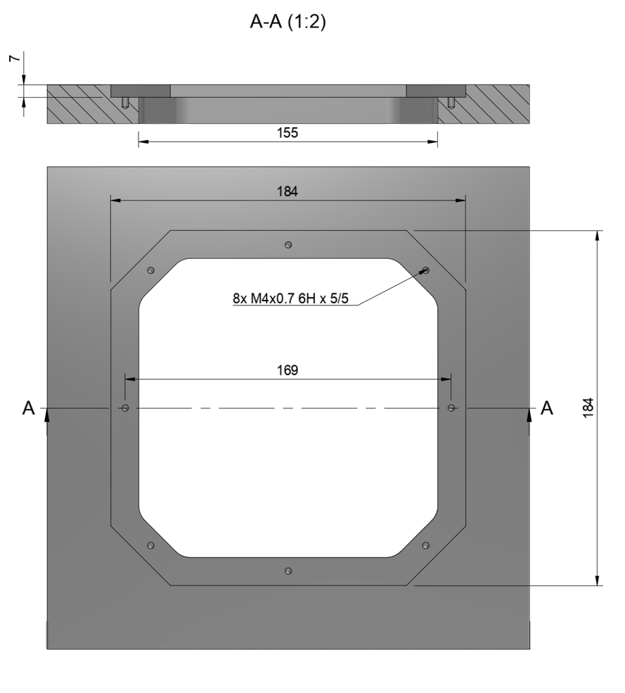
After installation, it is recommended to verify the correctness of the compass reading and, if necessary, correct the compass calibration.
Wiring Transmitter
The transmitter only requires power to operate. The transmitter can be powered via a 8-pin connector located nearby. External compass (IMU) and control data can be send over UART and CAN protocol. See pinout information of transmitter.
Configure transmitter in ULS-Tools
ULS-ProCopter on beta stage now pls use Beta version of ULS-Tools for configuration and firmware update.
https://github.com/UAVLAS/ULSTools-Beta/releases/
To apply any changes, press "Apply Config" button at the bottom of the field.
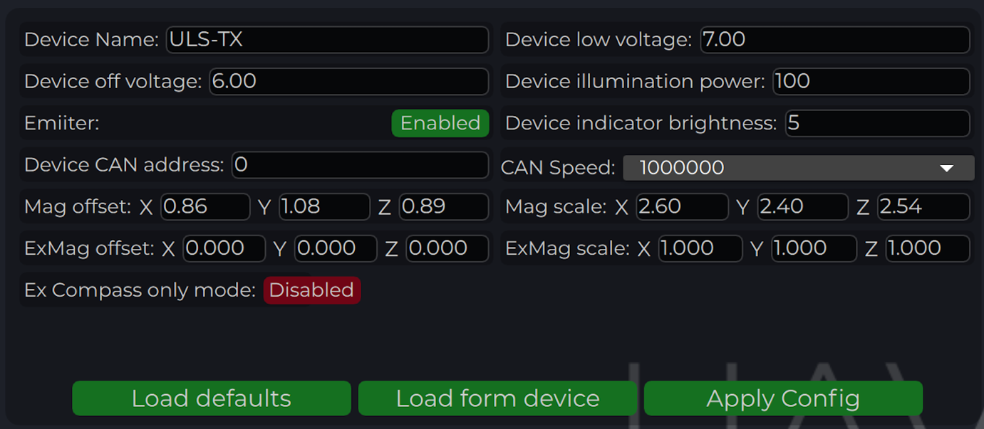
| Parameter | Description |
|---|---|
| Device name | Name of the device displayed in main window |
| Device low voltage | Voltage limit to start indicator flash warning |
| Device off voltage | Voltage limit to disable IR emitters to prevent battery under discharge |
| Device illumination power | Emitters power correction (100 for normal operation) |
| Emitter (enable/disable) | Disable (for configure) or enable emitter |
| Device Indicator Brightness | Adjust transmitter RGB led indicator brightness |
| Device CAN address/speed | Setup external CAN interface parameters |
| Compass Override (enable/disable) [deg] | Enable in case of module installed on fixed platform. The entered value will be used instead of internal compass data in “Compass mode”. In this way, the transmitter must be turned on the corresponding angle, CW to North. |
| Mag(ExMag) offset/scale | Calibration parameters for internal/external magnetometer |
| ExCompass mode only | If enabled - system will not use internal compass. If external compass data unavailable system generate error. If disabled internal compass will be used if External magnetometer unavailable |
Table: Transmitter Configuration Parameters
Compass calibration
This compass is used to calculate an absolute heading of the ground unit. This information is transmitted to the Receiver and used to calculate NED coordinates. To be able to use compass, it needs to be calibrated before. To calibrate compass:
- Press “Reset calibrations”.
- Rotate device in different directions until you get 3 circles on charts (see picture below).
- Press “Apply calibration” & “Apply configuration”.
During of calibration you can press "Clear chart" to reset previous compass measurements.
Compass chart before calibration:
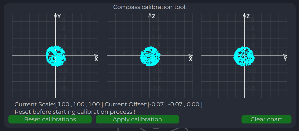
Compass chart after calibration:
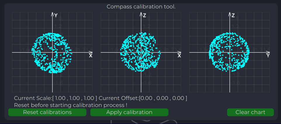
Charts Transmitter
Program display several parameters of the device on charts:
- IMU data.
- Voltage (not valid when powered from USB).
- Temperature data.
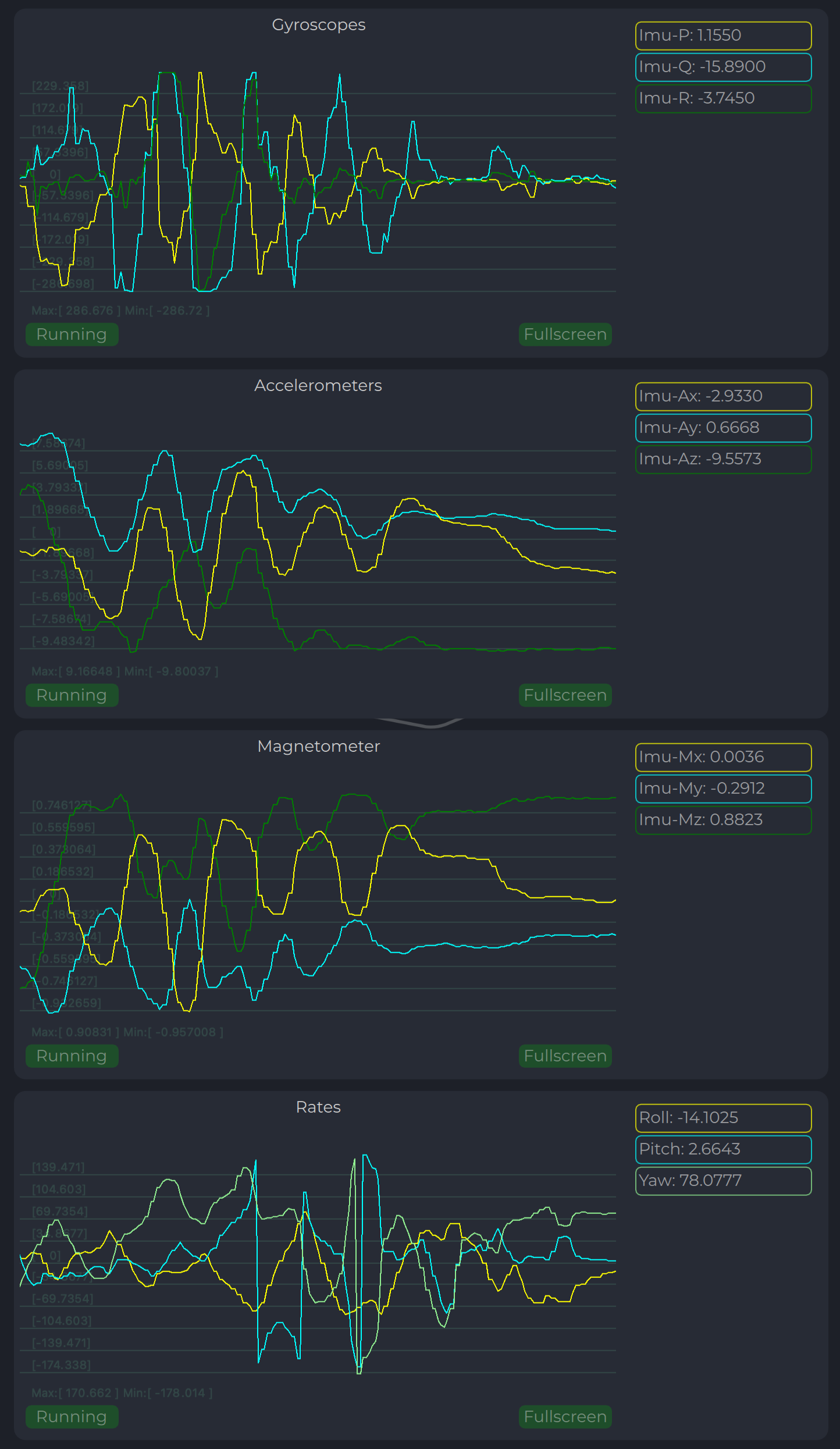
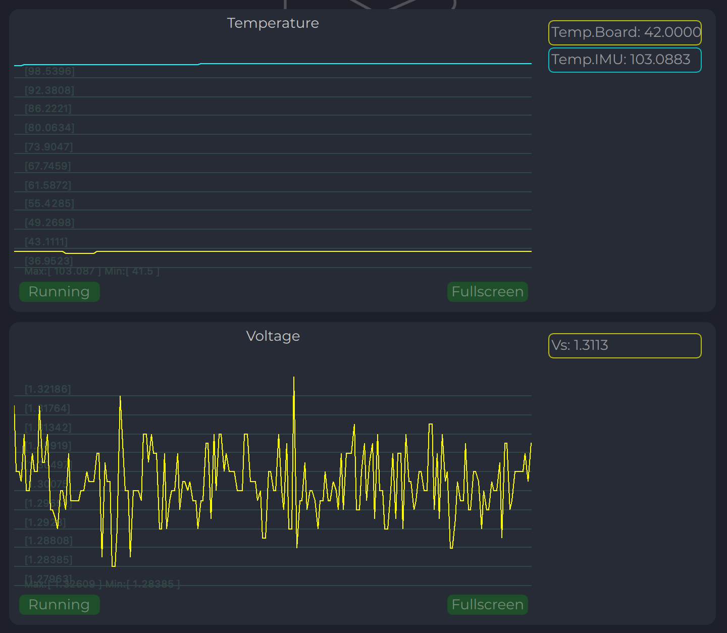
Led Indicator
You can check the status of the transmitter looking on the LED indicator on the transmitter. LED flashes in sequences of colors, so it can flash green-red-off-off or green-off-blue-off.
| Flash color | Description |
|---|---|
| Green | Normal operation. |
| Orange | Low voltage. |
| Red | Problem, check device. If it is first in sequence it can be led malfunctions of power voltage below minimum, second for compass fail detect. |
| Blue | Compass ok and device points to the North (brightness of illumination depends on how precise it is pointed to the North). |
Table: LED Indicator Status Colors
On-board unit installation (receiver)
The receiver can be installed both inside and outside the vehicle. However, please note that this version of the system is not equipped with protection against moisture and dust. The orientation of the receiver does not matter - however, when installing the receiver, care should be taken to ensure line-of-sight conditions between the transmitter and receiver throughout the entire field of view of the receiver (100 deg). The receiver sensor zone is indicated in the figure.
Once the receiver is installed, enter the appropriate receiver offset information into the configuration.
Wiring Receiver Pixhawk 4 autopilot connection using UART
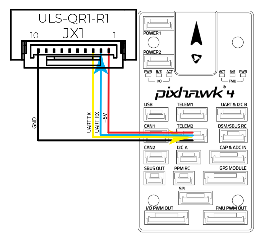
Wiring for MultiRX mode (MRX)
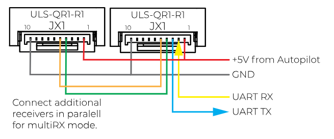
Configure Receiver in ULS-Tools
Note:
To apply any changes, press “Apply Config” button at the bottom of the field.
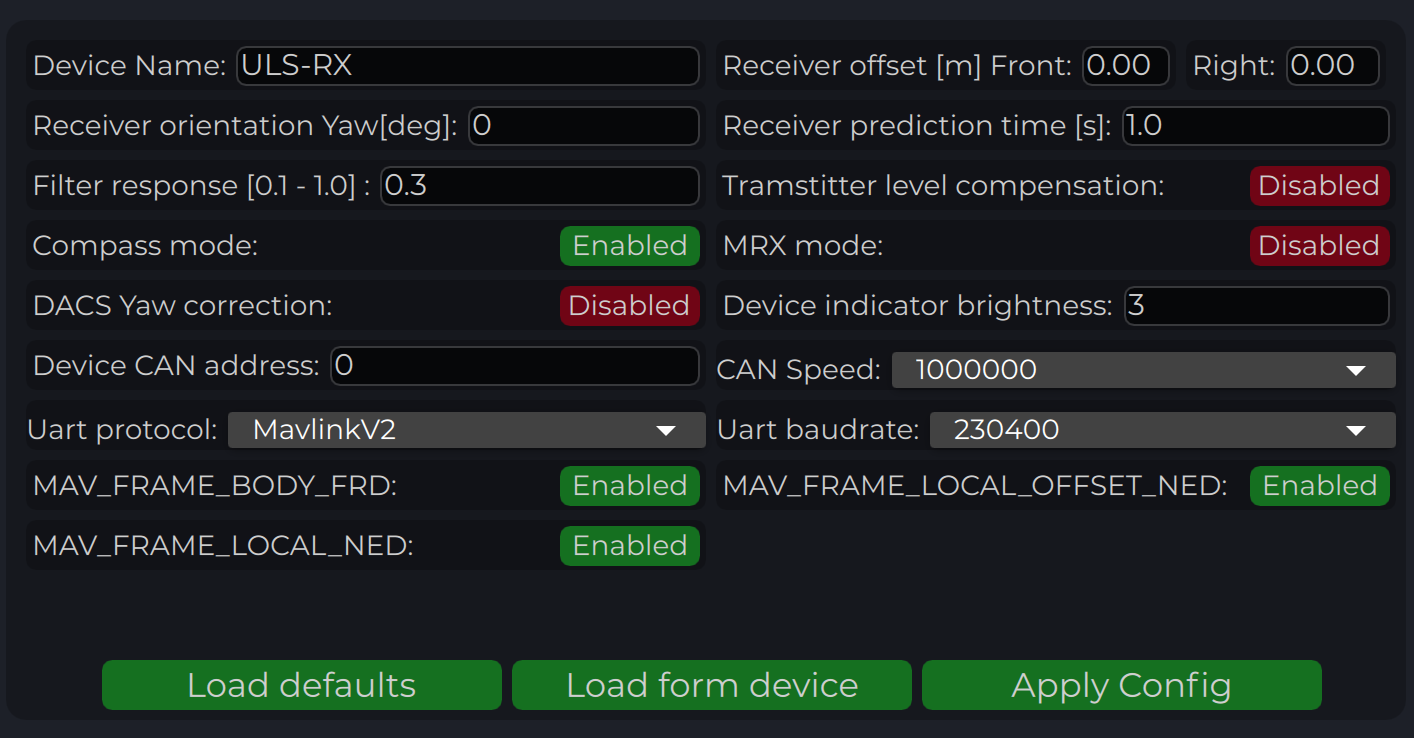
| Parameter | Description |
|---|---|
| Device name | Name of the device displayed in main window. |
| Receiver offset (Front, Right) [m] | Location of receiver in the drone (in meters). This configuration used to calculate drone heading in MultiRX mode. |
| 2Receiver prediction time [s] | Prediction time is used to send prediction information of landing position. It is useful to avoid the effect of short terms signal interruptions. Generally, its value can be set from 0.3 up to 1 sec. |
| Filter response | Set response for internal position filter of receiver. Hi values make lag time shorter, lower values smooth position information. |
| Transmitter level compensation | Used to compensate Pan-Tilt rotations of the transmitter. It is used in case of landing on the moving objects. |
| Noise debug | Use this function to check the noise interference with other devices. In this mode, receiver do not receive the signal from the transmitter, but can capture all the other signals. At the time of the test, transmitter must be switched off, and you can see on Signal Viewer the level of noise and detect what devices around affect the receiver. In general, max level of noise needs to be lower than 0.0025 for Beans B channel. NO OPERATIONS CAN BE PERFORMED IF THIS OPTION IS ENABLED - switch off before the normal use. |
| Compass mode (disable/enable) | If settings are disabled - receiver will not perform data calculation based on ground compass data. Multi RX mode and (or) compass mode must be enabled to allow the operation. |
| MRX mode (disable/enable) | If settings are enabled - receiver will use secondary receiver to perform the data calculation. Multi RX mode and (or) compass mode must be enabled to allow the operation. |
| Device Indicator Brightness | Adjust transmitter led indicator brightness |
| Device CAN address/speed | Setup external CAN interface parameters |
| UART Protocol | Select corresponding protocol to communicate with autopilot. If protocol “MavlinkV2” is selected, you can enable the corresponding MAV_FRAME message to be sent to the autopilot (Ardupilot - MAV_FRAME_BODY_FRD and PX4 MAV_FRAME_LOCAL_NED for now) |
| UART baud rate | Select UART communication speed. |
Table: Receiver Configuration Parameters
Status Information field
In the status display area, you can check the status of the receiver and visualise the position of the receiver relative to the drone.
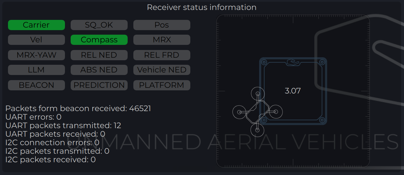
| Parameter | Description |
|---|---|
| Carrier | The carrier signal from transmitter is detected. |
| SQ_OK | Signal quality of the carrier is ok. |
| Pos | RAW sensor position is estimated. |
| Vel | RAW sensor velocity. |
| Compass | Ground unit orientation is received. |
| MRX | Secondary sensor for MRX mode is connected and sending data. |
| MRX-YAW | Yaw orientation is calculated using MRX. |
| REL-NED | Relative NED position is calculated. |
| REL-FRD | Relative FRD position is calculated. |
| LLM | Lat Lon Msl position is available (reserved for future options). |
| ABS-NED | Absolute position of transmitter is available. |
| VEHICLE-NED | Absolute position of vehicle is provided by the autopilot (used to calculate ABS position data). |
| BEACON | Indicate System Ok state. |
| PREDICTION | Indicate when system uses predicted information for the calculation. |
| PLATFORM | Position of landing platform is provided by third party devices. |
Table: Receiver Status Information Fields
Setup MRX mode
This option enables to use data from two receivers to calculate position. It allows calculating receiver yaw orientation using triangular method. In this mode, compass data (on ground and on board) is not affecting the position estimation, so it is more durable way to land. In this mode the maximum distance is limited by 10 m and at altitude above, it will use compass mode.
To set up and check MRX mode do the following:
- Connect receivers on board with CAN BUS.
- Configure “Receiver offset” for both receivers.
- Configure “Receiver orientation YAW” for both receivers (XCopter-G2).
- Enable option “MRX mode”.
- After set up, hover the drone above the transmitter (1 m - 2 m) and check that Tdistance and Distance are the same (+/- 20%).
- Correct “Receiver offset” option in case of TDistance and Distance are not approximately the same. Increasing position between receivers increases Tdistance and backwards.
- Rotate Drove over transmitter (1 m - 2 m) and check the value of the MRX-YAW on chart “GU Orientation”. It needs to be corresponding to the heading of the drone relatively to the transmitter.
Check "Remote IMU", "Filter smoothness", "Receiver sensitivity", "Receiver prediction time", setting MUST be equal to ALL the receivers on the vehicle
Please note, you can connect receiver directly to PC using USB pins. It will make the set up and testing receiver much easier.
Receiver Charts
Program display several parameters of the device on charts:
- Angles, Positions in different coordinate systems
- Distance
- Vehicle information (position and velocity)
- Data from Transmitters IMU.
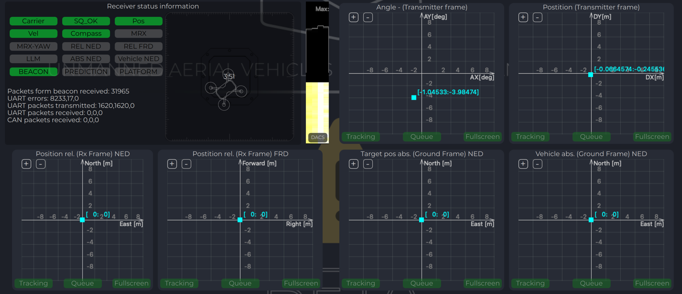
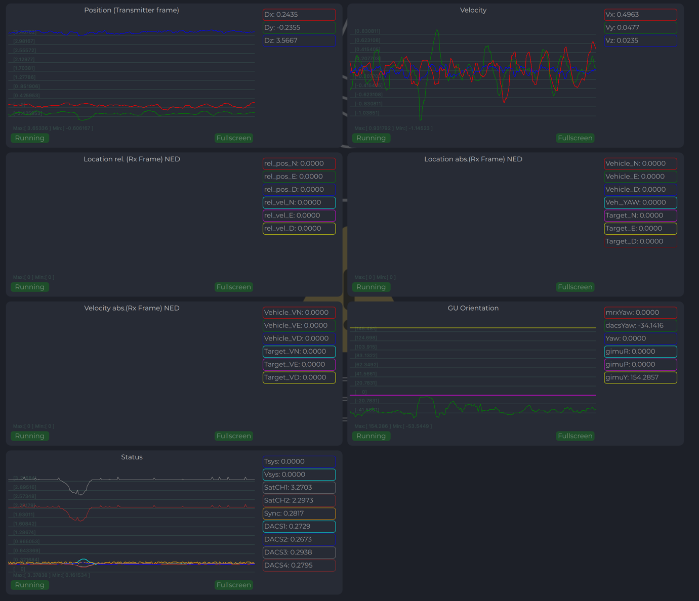
Integration instructions for Ardupilot based systems.
Preparing for integration:
- Download the latest version of the ULSTools software. It is recommended to connect all sensors to PC and update the firmware for all UAVLAS devices in the system.
- Update autopilot with Arducopter latest version.
- Configure transmitter.
- Configure receiver.
ULS-ProCopter software on beta stage now. Pls Use Beta version ULS-Tools for configuration and update.
Current version of the system can use MavlinkV2 protocol to communicate with Ardupilot autopilots (for now it supports MAV_FRAME_BODY_FRD).Example of receiver configuration:
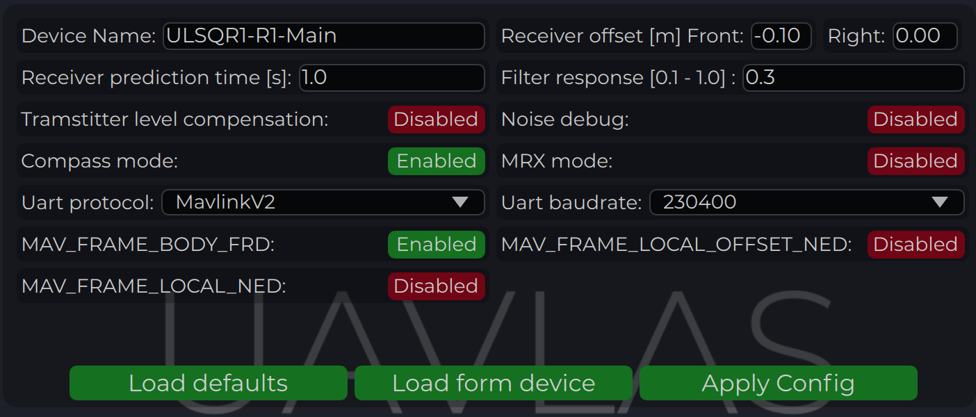
Autopilot configuration
Setup PLND section
| Param | Value | Comment |
|---|---|---|
| PLND_ENABLED | 1 | Enable precision landing module |
| PLND_TYPE | 1 | Use type = 1 to enable UAVLAS sensor over Companion computer driver |
Table: Ardupilot PLND Section Parameters All other parameters in PLND section defaults or use accordingly to your vehicle set up requirements.
On a picture example configuration provided.
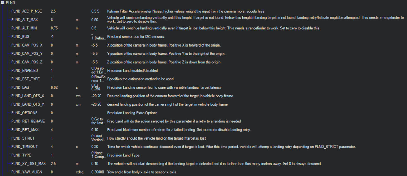
It is recommended to test several options of Kalman filter during the test flights (or switch it off) to achieve the best performance.
Set up serial communication in SERIALx Section.
| Param | Value | Comment |
|---|---|---|
| SERIAL2_BAUD | 230 | Select baud rate - it needs to be same as in receiver’s configuration. |
| SERIAL2_OPTIONS | 0 | Default |
| SERIAL2_PROTOCOL | 2 | MAVlink2 protocol support. |
Table: Serial Communication Configuration (SERIALx Section) Set up serial communication messages in SRx Section. Sensor requires some data from autopilot to work in different modes.
| Param | Value | Comment |
|---|---|---|
| SR2_EXTRA1 (or MAV2_EXTRA1) | 20 | Stream Attitude information (20Hz) (YAW Orientation is required for sensor in compass mode) |
| SR2_POSITION (or MAV2_POSITION) | 20 | Optional - Stream Vehicle position (20Hz) (LOCAL_POSITION_NED is required for sensor to provide LOCAL position for the target) |
Table: Serial Communication Messages (SRx Section) Check setup.
If all settings are done correct, autopilot has GPS data and receiver in the field of view of the transmitter, you can find LANDING_TARGET message in mavlink inspector (a screenshot from Mission Planner)
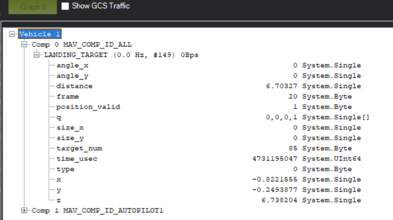
Setup Precision loiter mode.
To enable precision loiter mode you need attach any unused switch to PrecLoiter option see picture below:
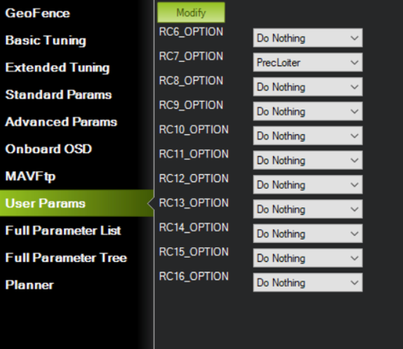
Try to use this switch and you must get messages: “PrecLoiter: LOW” and “PrecLoiter: HIGH” After test flight above target check telemetry - you will find PL data contains offsets form landing target.
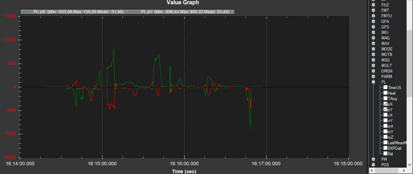
PID tuning
In case of oscillations and other issues at landing stage, pls, check PID parameters of Ardupilot.
It is recommended to check the Position XY, Velocity XY and Loiter speed parameters in “Extended tuning” section to achieve the best performance.
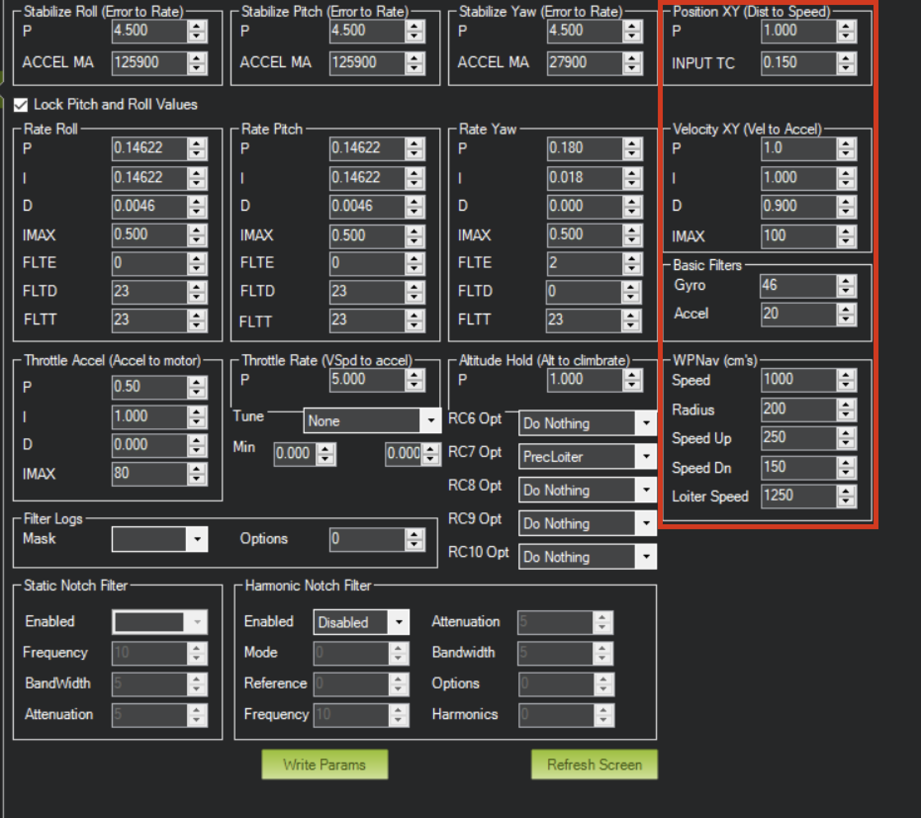
For example, settings Velocity XY P = 0.8, I = 0.2, and D = 0.6 works well for some of our customers
It recommended to start testing PIDs and precision system performance in "Precision Loiter" mode. I use some algorithms and settings in precision landing.
For additional information, see Ardupilot manual.
Integration instructions for PX4 based systems.
Preparing for integration:
- Download the latest version of the ULSTools software. It is recommended to connect all sensors to PC and update the firmware for all UAVLAS devices in the system.
- Update autopilot with PX4 latest version.
- Configure transmitter.
- Configure receiver.
ULS-ProCopter software on beta stage now. Pls Use Beta version ULS-Tools for configuration and update.
Current version of the system can use MavlinkV2 protocol to communicate with PX4 autopilots (for now it supports MAV_FRAME_LOCAL_NED).
Example of receiver configuration:
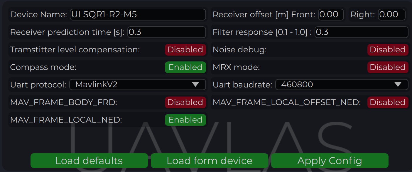
Configure PX4 autopilot.
Values are provided as example (in our case, Pixhawk4-mini AP)
| PX4 Parameter | Value |
|---|---|
| MAV_1_CONFIG | TELEM/SERIAL4 (require reboot to set next params) |
| MAV_1_FORWARD | Enabled. |
| MAV_1_MODE | Onboard. |
| SER_TEL4_BAUD | 460800_8N1 (It needs to be corresponding to the setting of UART in Receiver ULS-QR1-R1 connected to PX4 AP) |
Table: PX4 Autopilot Configuration Parameters
Running and testing
After configuration and wiring, power up drone and transmitter. On QGround control, go “Analyze Tools” -> MAVLINK Inspector. Check LANDING_TARGET MAVLINK message
In case the vehicle provide LOCAL_POSITION_NED message to UAVLAS system, and it hovers over beacon, you get “position_valid = 1” in LANDING_TARGET
To perform precision landing, you need to create a flight plan and enable Precision Landing option on the landing point.
LANDING_TARGET may be unavailable in case of connection over USB. So, use telemetry channel (uart modem etc.) to connect drone to the QGroundControl.
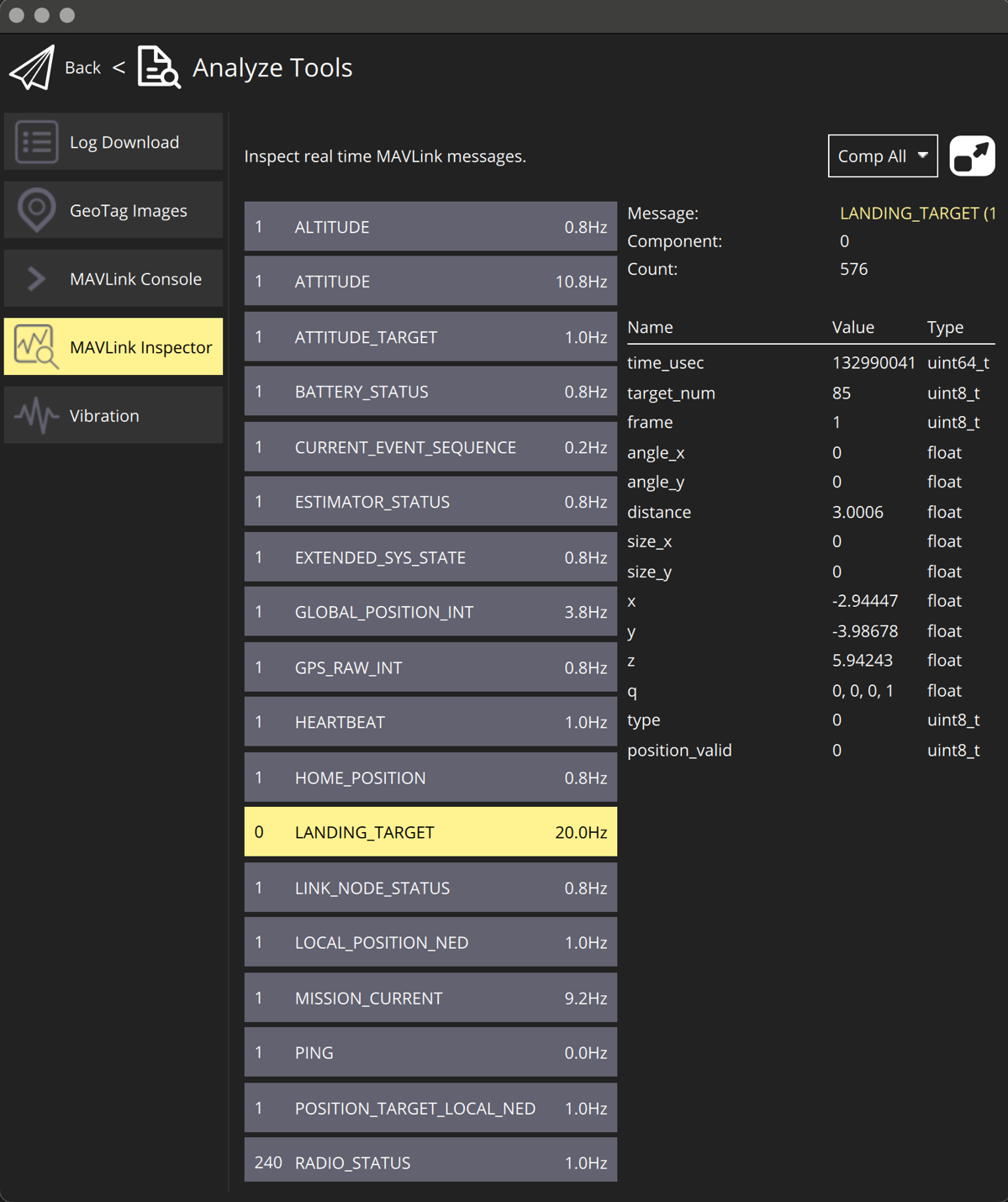
Troubleshooting
Before of all check:
- You are using latest version of ULS-Tools, latest firmware on ULS-XCOPTER transmitter and receiver, and latest Ardupilot (PX4) firmware.
No mavlink message:
- Transmitter are switched on and receiver in field of view of transmitter.
- Red light on receiver flashes fast ( > 5 times per second ). If it flash 2 times per sec it mean that transmitter not switched on, or not in field of view. If it not flash - check power.
- Check Serial setting on AP params and on receiver be sure you are set EXTRA params for corresponding serial port on AP.
- Check wiring power and RX, TX (see pinouts and wiring diagram)
- Check on receiver that MAV_FRAME_BODY_FRD (MAV_FRAME_LOCAL_NED) enabled.
Not holding in precision loiter mode but mavlink message ok:
- Check that you setup Precision loiter mode on AP
Circular motions during landing:
- Check compass calibration on ground unit.
- Check Compass calibration on AP.
- Check magnetic interference on ground.
- Use compass override mode to debug landing.
- Check precision landing PID settings.
The landing is not precise enough:
- Check the position control PID settings of AP.
- For Ardupilot check Kalman filter settings.
- Check filter smoothness param on receiver.
- Check trajectory Jerk settings on AP.
Change Control
All changes to this document must be reviewed and approved by the relevant technical leads and stakeholders
9.4 - ULS-ProCopter Precision Landing System
Document ULSDC-PBFL070425-L, version 1.0.0
ULSDC-PBFL070425-L · version 1.0.0 · issued 2025-11-11
The numbered PDF is the controlled copy: download it from the portal.
ULS-ProCopter Precision Landing System
Ultra-Compact Infrared UAV Landing Solution | 20m Range | Lightweight Design | -40°C to +85°C

Why Choose ULS-ProCopter?
✓ 20m Operating Range | ✓ Ultra-Compact Design | ✓ No Radio Connection Required | ✓ 20Hz Update Rate | ✓ Plug & Play Integration| ✓ Industrial Temperature Range
Next-generation precision landing technology for lightweight UAVs and multi-copters requiring accurate positioning and safe autonomous landing on stationary or moving platforms. The ULS-ProCopter system enables precise autonomous UAV landing through advanced infrared positioning technology. The system consists of a compact ground-based transmitter that emits coded infrared signals, and ultra-lightweight onboard receivers that calculate real-time position and orientation data.
How It Works
- Ground Transmitter (TX) - Compact infrared beacon continuously emits coded positioning signals in a >100° cone
- Onboard Receiver (RX) - Ultra-lightweight unit mounted on UAV decodes signals and calculates 6DOF position (X, Y, Z, Roll, Pitch, Yaw)
System Components
| Component | Size (mm) | Weight | FOV/Angle | Power | Details |
|---|---|---|---|---|---|
| Transmitter | 183×183×29 | 1200g | >100° emit | 18.4W, 12-27V | Ultra-compact ground beacon |
| Receiver | 18.4×33.4×6.9 | 10g | 100° | 0.3W, 5V | Miniature receiver with integrated processing |
Communication: USB, CAN, UART (115200 baud) | Autopilot Support: Ardupilot, PX4, Custom integration
Data Output: Position (X/Y/Z), Orientation (Roll/Pitch/Yaw), Signal quality, System status
Technical Specifications
Performance
| Feature | Value | Notes |
|---|---|---|
| Operating Range | 0.1 - 20m | Optimal performance throughout range |
| Update Rate | 20Hz | Real-time position updates |
| Accuracy | ±5cm | Consistent across operating range |
| Latency | <50ms | End-to-end signal processing |
| Transmitter Angle | >100° cone | Wide coverage landing zone |
| Receiver FOV | 100° | Wide field of view for approach |
| Operating Temp | -40°C to +85°C | Extended industrial grade |
| Storage Temp | -40°C to +85°C | Same as operating range |
| Protection | IP40 | Suitable for indoor/outdoor use |
| Weight Penalty | 10g | Ultra-lightweight receiver |
Applications & Use Cases
Primary Applications
🚁 Multi-copter Landing - Precision landing for lightweight drones and racing quadcopters
📦 Delivery Drones - Accurate package delivery to designated landing zones
🏭 Industrial Inspection - Reliable landing for confined spaces and structures
🎬 Cinematography - Precise positioning for aerial filming and photography platforms
Key Benefits
- Ultra-Lightweight - Only 10g receiver weight, minimal impact on flight time
- Compact Footprint - Small transmitter size perfect for portable deployment
- Extended Temperature Range - Operates in extreme conditions from -40°C to +85°C
- Wide Field of View - >100° transmitter angle and 100° receiver FOV for easy approach
- No GPS Required - Operates in GPS-denied environments (indoors, urban areas)
- Plug & Play Integration - Compatible with major autopilot systems, minimal configuration
- Energy Efficient - Low 0.3W receiver power consumption
Contact Us
UAVLAS sp. z o.o. | 📧 info@uavlas.com | 🌐 www.uavlas.com |
ULS-ProCopter - Precision Landing, Minimal Weight
9.5 - ULS-ProCopter Precision Landing System
Document ULSDC-PBFL070425, version 1.0.0
ULSDC-PBFL070425 · version 1.0.0 · issued 2025-11-11
The numbered PDF is the controlled copy: download it from the portal.
ULS-ProCopter Precision Landing System
Ultra-Compact Infrared UAV Landing Solution | 20m Range | Lightweight Design | -40°C to +85°C
Why Choose ULS-ProCopter?
✓ 20m Operating Range | ✓ Ultra-Compact Design | ✓ No Radio Connection Required | ✓ 20Hz Update Rate | ✓ Plug & Play Integration| ✓ Industrial Temperature Range
Next-generation precision landing technology for lightweight UAVs and multi-copters requiring accurate positioning and safe autonomous landing on stationary or moving platforms. The ULS-ProCopter system enables precise autonomous UAV landing through advanced infrared positioning technology. The system consists of a compact ground-based transmitter that emits coded infrared signals, and ultra-lightweight onboard receivers that calculate real-time position and orientation data.
How It Works
- Ground Transmitter (TX) - Compact infrared beacon continuously emits coded positioning signals in a >100° cone
- Onboard Receiver (RX) - Ultra-lightweight unit mounted on UAV decodes signals and calculates 6DOF position (X, Y, Z, Roll, Pitch, Yaw)
System Components
| Component | Size (mm) | Weight | FOV/Angle | Power | Details |
|---|---|---|---|---|---|
| Transmitter | 183×183×29 | 1200g | >100° emit | 18.4W, 12-27V | Ultra-compact ground beacon |
| Receiver | 18.4×33.4×6.9 | 10g | 100° | 0.3W, 5V | Miniature receiver with integrated processing |
Communication: USB, CAN, UART (115200 baud) | Autopilot Support: Ardupilot, PX4, Custom integration
Data Output: Position (X/Y/Z), Orientation (Roll/Pitch/Yaw), Signal quality, System status
Technical Specifications
Performance
| Feature | Value | Notes |
|---|---|---|
| Operating Range | 0.1 - 20m | Optimal performance throughout range |
| Update Rate | 20Hz | Real-time position updates |
| Accuracy | ±5cm | Consistent across operating range |
| Latency | <50ms | End-to-end signal processing |
| Transmitter Angle | >100° cone | Wide coverage landing zone |
| Receiver FOV | 100° | Wide field of view for approach |
| Operating Temp | -40°C to +85°C | Extended industrial grade |
| Storage Temp | -40°C to +85°C | Same as operating range |
| Protection | IP40 | Suitable for indoor/outdoor use |
| Weight Penalty | 10g | Ultra-lightweight receiver |
Applications & Use Cases
Primary Applications
🚁 Multi-copter Landing - Precision landing for lightweight drones and racing quadcopters
📦 Delivery Drones - Accurate package delivery to designated landing zones
🏭 Industrial Inspection - Reliable landing for confined spaces and structures
🎬 Cinematography - Precise positioning for aerial filming and photography platforms
Key Benefits
- Ultra-Lightweight - Only 10g receiver weight, minimal impact on flight time
- Compact Footprint - Small transmitter size perfect for portable deployment
- Extended Temperature Range - Operates in extreme conditions from -40°C to +85°C
- Wide Field of View - >100° transmitter angle and 100° receiver FOV for easy approach
- No GPS Required - Operates in GPS-denied environments (indoors, urban areas)
- Plug & Play Integration - Compatible with major autopilot systems, minimal configuration
- Energy Efficient - Low 0.3W receiver power consumption
Contact Us
UAVLAS sp. z o.o. | 📧 info@uavlas.com | 🌐 www.uavlas.com |
ULS-ProCopter - Precision Landing, Minimal Weight
10 - ULS-XCopter-G2
Production
10.1 - ULS-XCopter-G2 Datasheet
Datasheet ULSDC-PBDS310325, version 0.1.0
ULSDC-PBDS310325 · version 0.1.0 · issued March 31, 2025
The numbered PDF is the controlled copy: download it from the portal.
Introduction
Purpose
The purpose of this datasheet is to provide comprehensive technical information about the ULS-XCopter-G2 System family. This includes specifications, performance characteristics, and detailed descriptions of system components, such as transmitters and receivers. By outlining the interfaces between these components, the datasheet aims to facilitate seamless integration and operation for system engineers, integrators, and developers working with the system.
Scope
This document is intended for use by system engineers, integrators, and developers working with ULS-XCopter-G2 systems. It provides detailed information on the system components, specifications, interfaces, and operational characteristics.
System Base Components
Transmitter (Ground Unit)
A transmitter is a device placed on the ground (platform, moving object). It emits a signal in the Infrared range and serves as a kind of beacon. Transmitter marks position for drone landing.
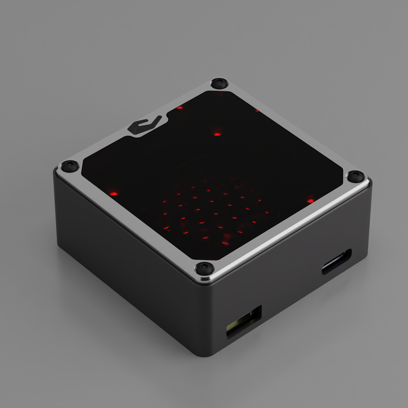
The primary function of the transmitter is to continuously send out a coded signal that can be detected and interpreted by the receiver unit onboard the XCopter. This signal contains critical information needed for the operation of the ULS-XCopter, such as positional data, commands, and system status.
Receiver (Onboard Unit)
A receiver is a device that is placed on board an aircraft.
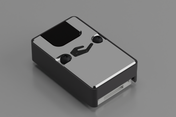
The receiver decodes this signal to derive flight information such as positional coordinates, real-time transmitter status updates, and landing guidance. It interprets the data to navigate accurately and ensure drone follows the intended flight path. It provides feedback to the autopilot systems, such as Ardupilot and PX4, to adjust the flight parameters as needed for optimal and safety landing or hovering above.
Part Numbering
| Part Number | Description |
|---|---|
| ULS-XCopter-G2 | System set with 1 receiver. Generation 2. |
| ULS-XCopter-G2-MRX | System set with 2 receivers. Generation 2. |
| ULSDV-XC-G2-TX | Transmitter unit. Generation 2. |
| ULSDV-XC-G2-RX | Receiver unit. Generation 2. |
| GHR-10V-S | 10 Pin Connector for receiver. Manufacturer, JST Commercial. |
| GHR-06V-S | 6 Pin Connector for transmitter. Manufacturer, JST Commercial. |
| GHR-04V-S | 4 Pin Connector for transmitter. Manufacturer, JST Commercial. |
Table: ULS-XCopter-G2 Part Numbers
System Specifications
Common Specification
| Parameter | XCopter-G2 |
|---|---|
| Distance range (m) | 0.1 - 20.0 |
| Working angle (deg) | 60 |
| Data update frequency (Hz) | 20 |
Table: Common System Specifications
Receiver (Onboard Unit)
| Parameter | XCopter-G2 |
|---|---|
| Field of view (deg) | 100 |
| Dimensions (mm) | 20 x 32 x 9 |
| Weight (g) | 10 |
| Power Consumption (W) | 0.3 |
| Voltage supply (V) | 5.0 |
| Interfaces | USB, CAN, UART |
Table: Receiver Specifications
Transmitter (Ground Unit)
| Parameter | XCopter-G2 |
|---|---|
| Field of emitting (deg) | 60 |
| Dimensions (mm) | 50 x 50 x 23 |
| Weight (g) | 45 |
| Power Consumption (W) | 2.4 |
| Voltage supply (V) | 7.5 - 27 |
| Interfaces | USB, CAN, UART |
Table: Transmitter Specifications
Please note that if you use a USB cable to connect the ULS-XCopter-G2 transmitter and power is supplied via this cable, you must ensure that the cable and power supply allows at least 3A. If the power supply or cable does not allow 5V 3A to be delivered to the transmitter, the device may not work properly. In this case it is recommended to use an external power supply of 7.5-24V connected to connector JX1 - External power and control.
Pinout Information
Receiver Pinout
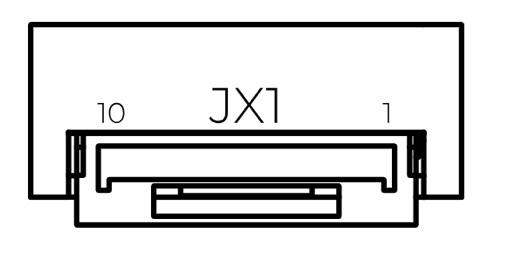
Figure: ULS-XCopter-G2 Receiver Connector
| Pin Number | XCopter-G2 |
|---|---|
| 1 | +5V Input |
| 2 | UART RX |
| 3 | UART TX |
| 4 | CAN H |
| 5 | CAN L |
| 6 | USB D- |
| 7 | USB D+ |
| 8 | UART2 RX |
| 9 | UART2 TX |
| 10 | GND |
Table: Receiver Pinout (JX1)
Transmitter Pinout
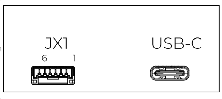
Figure: ULS-XCopter-G2 Transmitter Main Connector
| Pin Number | XCopter-G1&G2 |
|---|---|
| 1 | Vcc Input (+7.5V..+27V) |
| 2 | CAN2 H |
| 3 | CAN2 L |
| 4 | UART TX |
| 5 | UART RX |
| 6 | GND |
Table: Transmitter Main Connector Pinout (JX1)
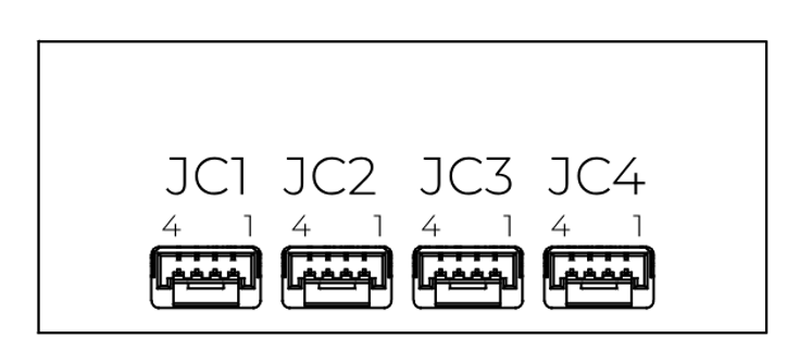
Figure: ULS-XCopter-G2 Transmitter Submodule Connectors
| Pin Number | XCopter-G1&G2 |
|---|---|
| 1 | +5V Output |
| 2 | CAN1 H |
| 3 | CAN1 L |
| 4 | GND |
Table: Transmitter Submodule Connectors Pinout (JC1-JC4)
Mechanical Dimensions
Receiver (G2) Dimensions
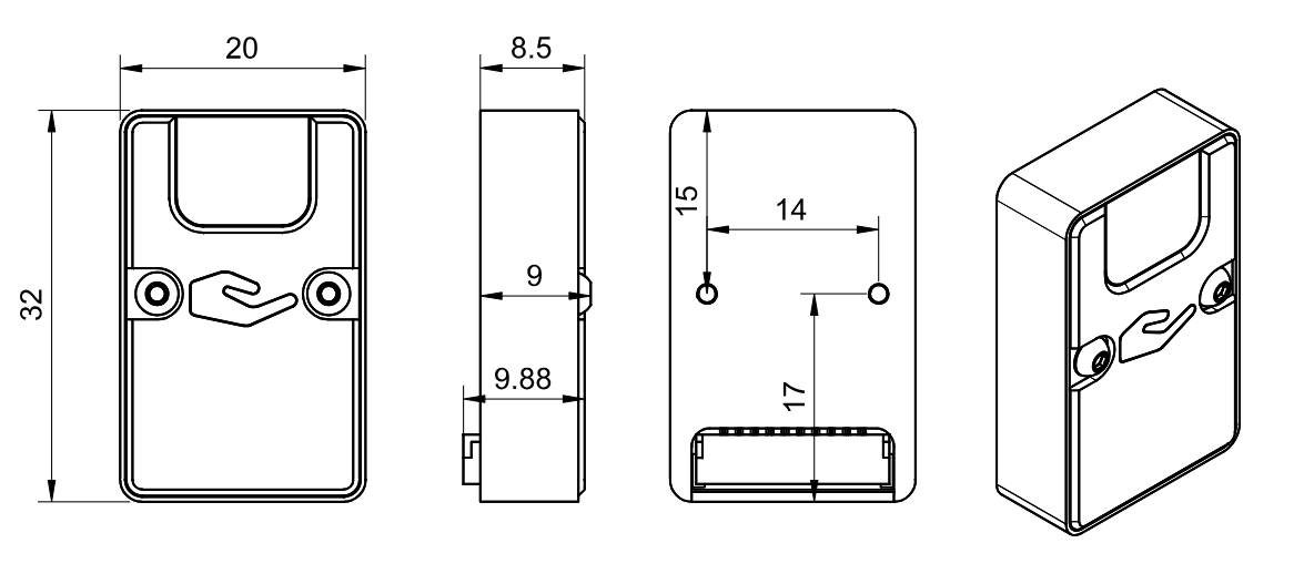
Figure: ULS-XCopter-G2 Receiver Dimensions (mm)
Transmitter (G2) Dimensions
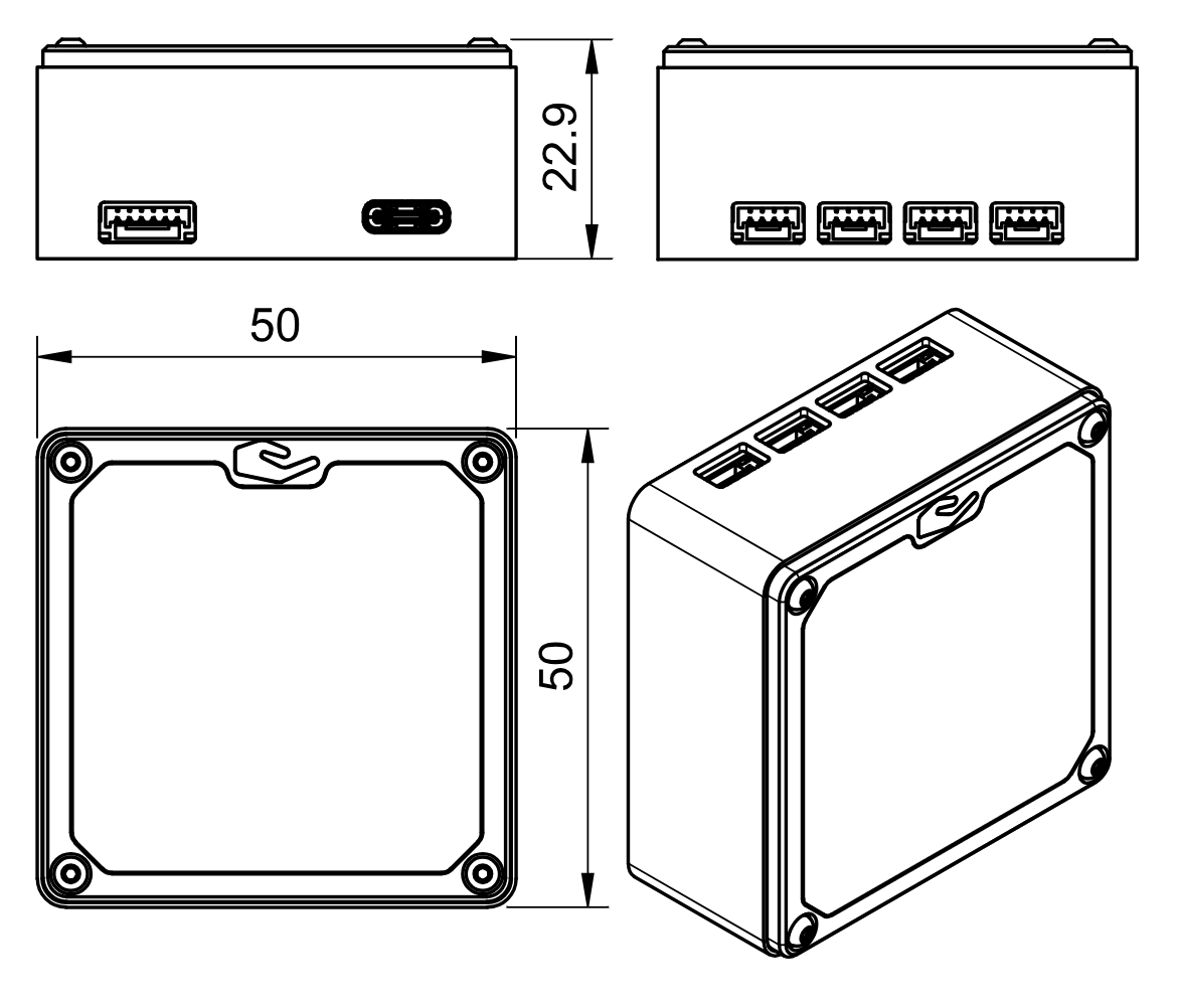
Figure: ULS-XCopter-G2 Transmitter Dimensions (mm)
Environmental Conditions
The system is designed for commercial-grade environmental operation, suitable for outdoor and industrial applications where robust performance under varying environmental conditions is required.
Operating Temperature
The system components are rated for extended temperature operation:
- Normal Operation: -20°C to +45°C when mounted on vehicle PCB
The wide operating temperature range enables deployment in diverse climates, from cold weather operations to hot desert environments.
Environmental Protection
- IP Protection Rating: IP54 (dust protected, splash water resistant)
- Note: While the system offers protection against dust ingress and water splashing, it is not waterproof. Additional protective measures may be required for operation in harsh weather conditions or marine environments.
Storage and Handling
- Storage Temperature: -40°C to +85°C
- Humidity: Up to 95% non-condensing
- Altitude: Operation up to 4000m above sea level
Environmental Considerations
Dust Protection: The IP54 rating provides protection against dust ingress that could interfere with system operation. Regular cleaning is recommended in particularly dusty environments.
Moisture Resistance: Protected against water splashing from any direction. However, avoid direct water jets, submersion, or prolonged exposure to heavy rain without additional protective enclosures.
Thermal Management: Ensure adequate ventilation around system components during operation. Avoid mounting in locations exposed to direct sunlight or near heat sources that could cause components to exceed maximum operating temperature.
Condensation: When moving equipment between environments with significant temperature differences, allow sufficient time for thermal equalization to prevent internal condensation.
| Parameter | Minimum | Maximum | Unit | Notes |
|---|---|---|---|---|
| Operating Temperature | -25 | +45 | °C | Normal operation |
| Storage Temperature | -40 | 85 | °C | Non-operating |
| Humidity | 5 | 95 | % | Non-condensing |
| IP Protection Rating | IP54 | Dust and splash resistant | ||
| Altitude | 0 | 4000 | m | Above sea level |
Table: Environmental Specifications - Commercial Grade
Performance Characteristics
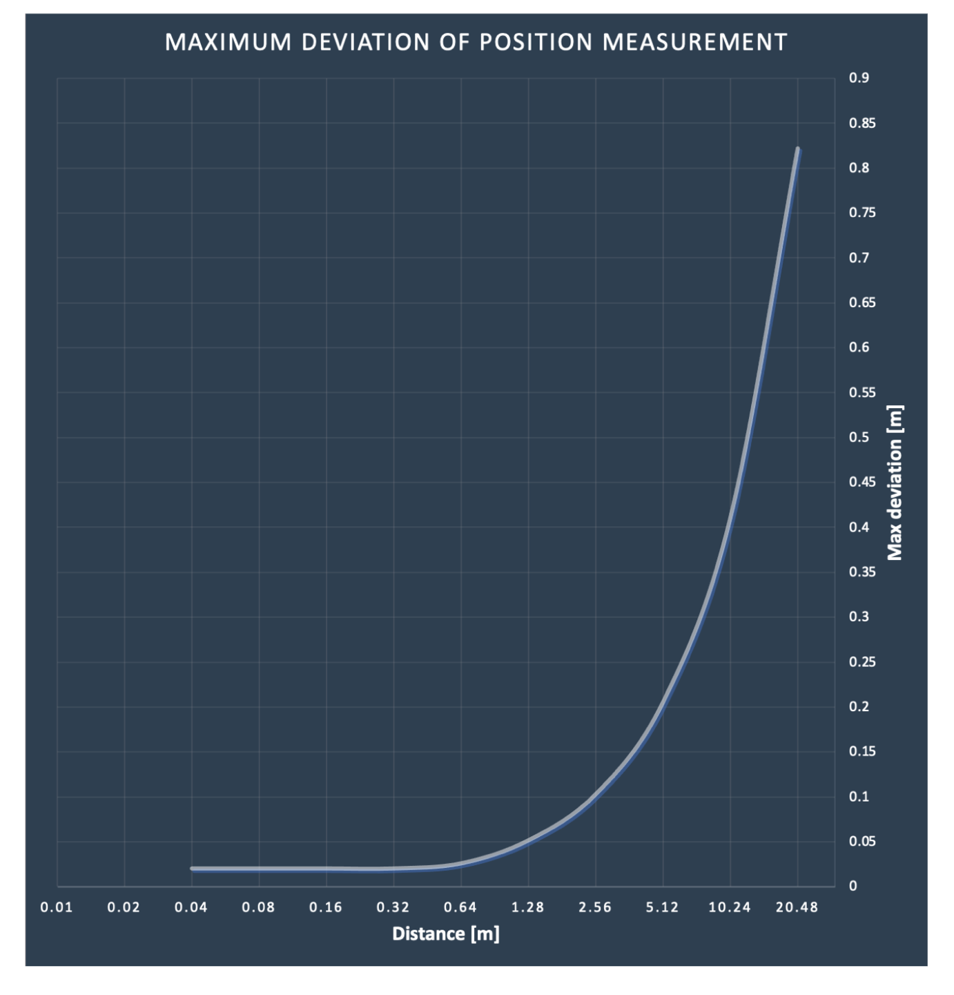
Figure: ULS-XCopter-G2 Performance Characteristics
Packaging Information
Basic System (PN: ULS-XCopter-G2)
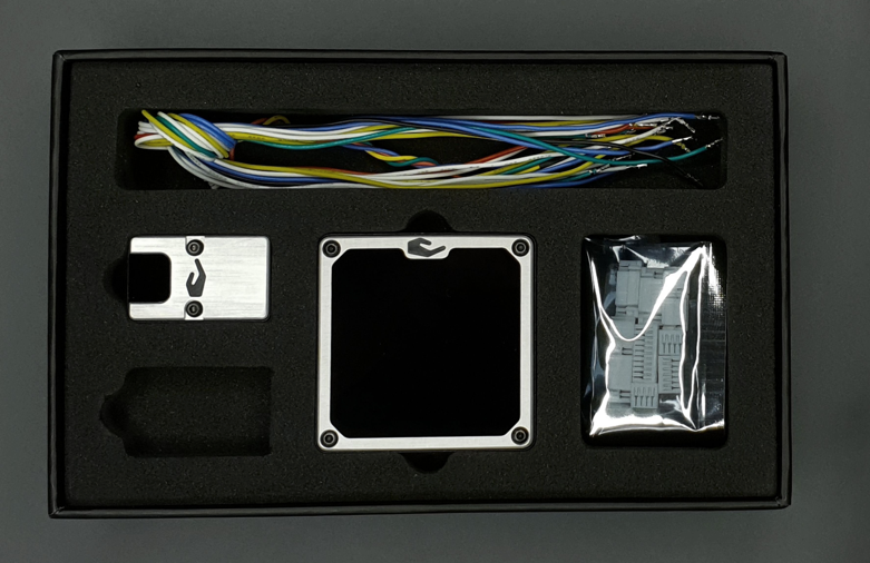
Figure: ULS-XCopter-G2 System Packaging
Advanced System (PN: ULS-XCopter-G2-MRX)
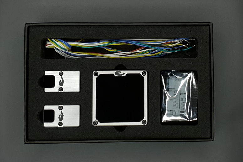
Figure: ULS-XCopter-G2-MRX
Some package contents (like cables and connectors) are subject to change.
Packed systems

Figure: ULS-XCopter-G2 in boxes
10.2 - ULS-XCopter-G2 Interface Control Document
Interface Control Document ULSDC-PBICD310325, version 0.1.0
ULSDC-PBICD310325 · version 0.1.0 · issued April 2, 2025
The numbered PDF is the controlled copy: download it from the portal.
Introduction
Purpose
This document outlines the interfaces between the ULS-XCopter-G2 system components, including the transmitter, receiver, and autopilot systems (Ardupilot and PX4 and similar).
Scope
This document is intended for use by system engineers, integrators, and developers working with ULS-XCopter-G2 systems. It provides detailed information on the interfaces between the system components, ensuring seamless integration and operation.
System Components
Transmitter (Ground Unit)
A transmitter is a device placed on the ground (platform, moving object). It emits a signal in the Infrared range and serves as a kind of beacon. Transmitter marks position for drone landing.
The primary function of the transmitter is to continuously send out a coded signal that can be detected and interpreted by the receiver unit onboard the XCopter. This signal contains critical information needed for the operation of the ULS-XCopter, such as positional data, commands, and system status.
Receiver (Onboard Unit)
A receiver is a device that is placed on board an aircraft.
The receiver decodes this signal to derive flight information such as positional coordinates, real-time transmitter status updates, and landing guidance. It interprets the data to navigate accurately and ensure drone follows the intended flight path. It provides feedback to the autopilot systems, such as Ardupilot and PX4, to adjust the flight parameters as needed for optimal and safety landing or hovering above.
Interface Overview
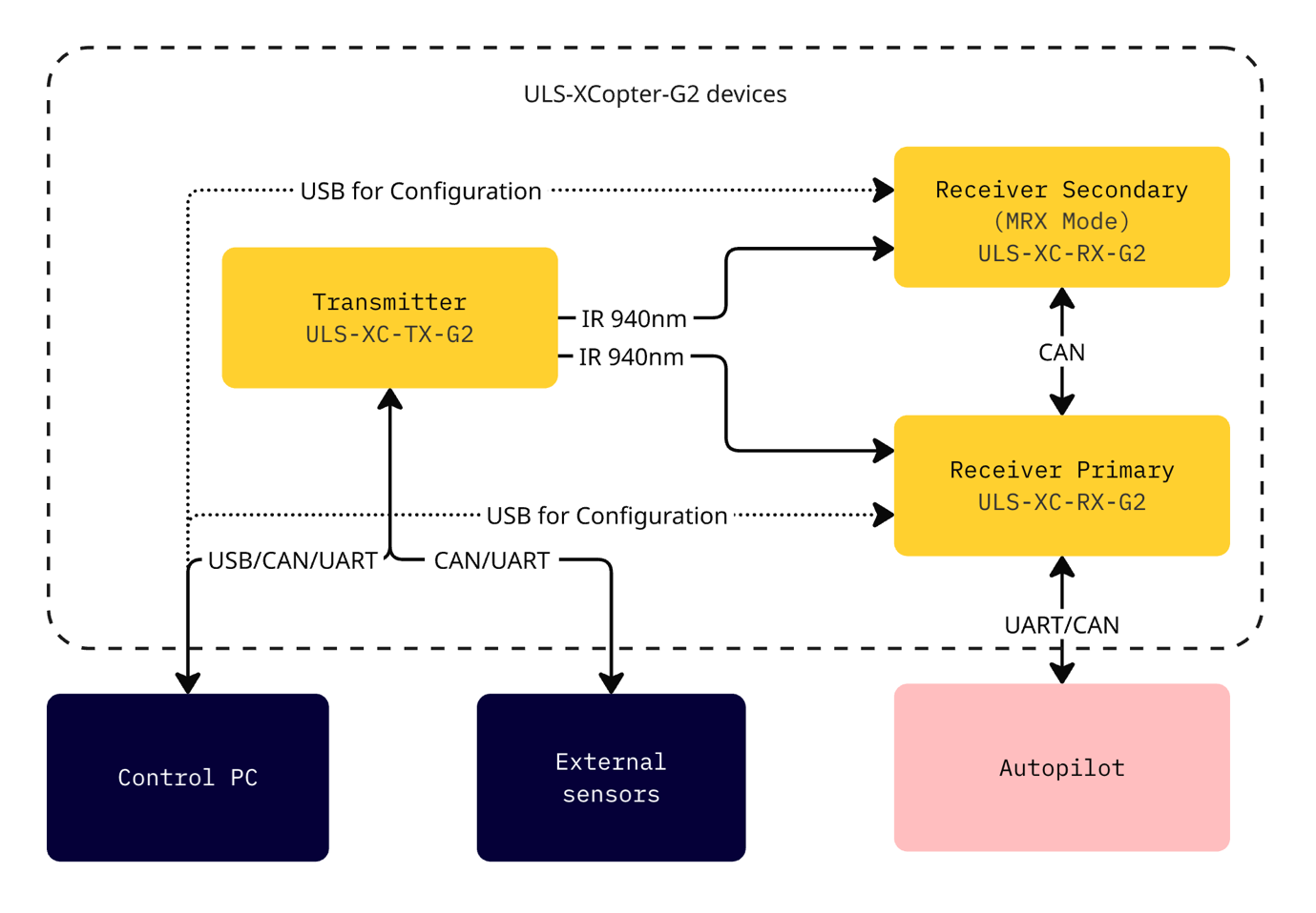
Figure: ULS-XCopter-G2 Interface Overview
Transmitter to Control PC Interface
Data Type:
- Status information
- Control signals
- Transmitter configuration
Connection Type:
- CAN
- USB
- UART
Transmitter to External Sensors Interface
Data Type:
- Control signals
- External IMU/COMPASS data
Connection Type:
- CAN
- UART
Transmitter to Receiver Interface
The transmitter and receiver use an optical interface to exchange data. Transmission uses IR emission at 940 nanometers. Data transmission is only in the direction from the transmitter to the receiver.
Data Type:
- Position encoded data
- Status encoded data (Transmitter orientation and instructions)
Connection Type:
- Optical IR 940nm (Infrared optical link)
Data Flow:
Data is transmitted unidirectional from the transmitter (ground unit) to the receiver (onboard unit) via infrared optical signals. The receiver decodes the optical signals to extract:
- Positional field information
- Ground unit IMU data
- System status and commands
Transmitter Pinout
Figure: ULS-XCopter-G2 Transmitter Main Connector
| Pin Number | XCopter-G1&G2 |
|---|---|
| 1 | Vcc Input (+7.5V..+27V) |
| 2 | CAN2 H |
| 3 | CAN2 L |
| 4 | UART TX |
| 5 | UART RX |
| 6 | GND |
Table: Transmitter Main Connector Pinout (JX1)
Figure: ULS-XCopter-G2 Transmitter Submodule Connectors
| Pin Number | XCopter-G1&G2 |
|---|---|
| 1 | +5V Output |
| 2 | CAN1 H |
| 3 | CAN1 L |
| 4 | GND |
Table: Transmitter Submodule Connectors Pinout (JC1-JC4)
Receiver to Autopilot and PC Interfaces
Data Type:
- Mavlink messages
- ULS-Blitz frames
- ASCII protocol
Connection Type:
- UART
- CAN
- USB
Data Exchange:
- Control PC is used to configure and view status of the receiver
- Autopilot Communication: Receiver accepts NED (North-East-Down) and attitude information from autopilot to convert coordinate systems
- Position Data: Receiver sends position offset data to autopilot
- Multi-Receiver Communication: Several receivers can communicate to calculate vehicle orientation (YAW)
receiver Pinout
Figure: ULS-XCopter-G2 Receiver Connector
| Pin Number | XCopter-G2 |
|---|---|
| 1 | +5V Input |
| 2 | UART RX |
| 3 | UART TX |
| 4 | CAN H |
| 5 | CAN L |
| 6 | USB D- |
| 7 | USB D+ |
| 8 | UART2 RX |
| 9 | UART2 TX |
| 10 | GND |
Table: Receiver Pinout (JX1)
Powering Interfaces
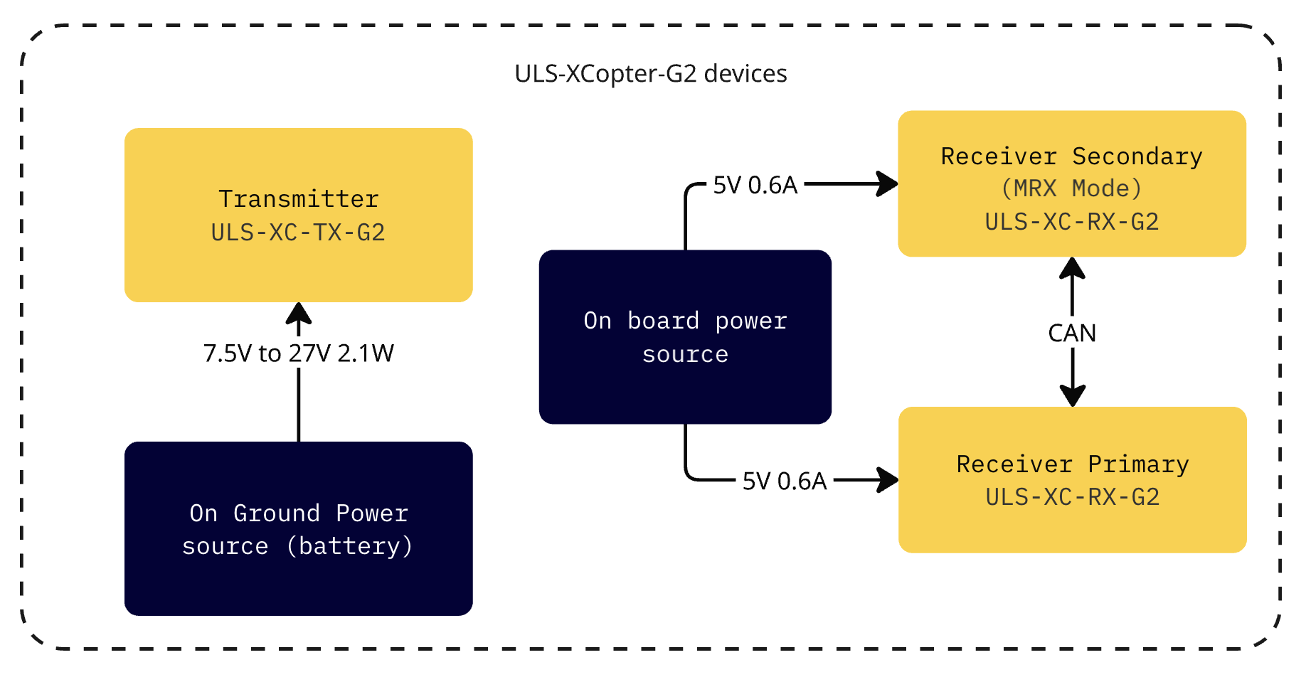
Figure: ULS-XCopter-G2 Powering Interfaces
| Parameter | Value | Unit |
|---|---|---|
| Supply Voltage | 7.5 - 27 | V |
| Supply Current | 2.0 | A |
| Power Consumption | 2.1 | W |
Table: Transmitter Electrical Characteristics
| Parameter | Value | Unit |
|---|---|---|
| Supply Voltage | 5.0 | V |
| Supply Current | 0.6 | A |
| Power Consumption | 0.3 | W |
Table: Receiver Electrical Characteristics
Functional Interfaces
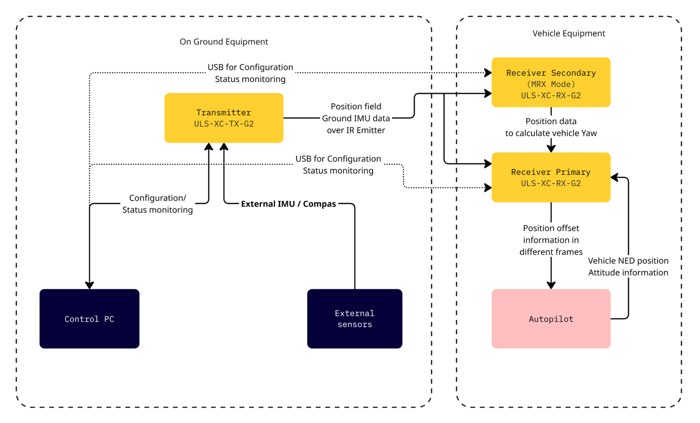
Figure: ULS-XCopter-G2 Functional Interfaces
Data Exchange
- Control PC used to configure and view status of transmitter.
- Control PC used to set configuration of receivers.
- Control PC (or embedded equipment instead control pc) can be used to send control signals (On/off, compass override information)
- External IMU/Compass equipment can be used to override internal IMU/compass information.
- Receiver accept data from transmitter over IR signal. This data include position field information and ground unit IMU data.
- Receiver accept NED and Attitude information from autopilot to be able convert coordinate system that can be accepted by autopilot.
- Several Receivers can communicate to be able calculate vehicle orientation YAW.
- Receiver send position offset data to autopilot.
Mechanical Interfaces
Transmitter Mechanical Interface
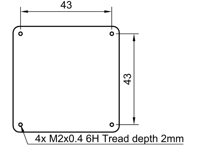
Figure: Transmitter Mechanical Interface
Figure: Transmitter dimensions
Receiver Mechanical Interface
Figure: Receiver Mechanical Interface
Environmental Conditions
The system is designed for commercial-grade environmental operation, suitable for outdoor and industrial applications where robust performance under varying environmental conditions is required.
Operating Temperature
The system components are rated for extended temperature operation:
- Normal Operation: -20°C to +45°C when mounted on vehicle PCB
The wide operating temperature range enables deployment in diverse climates, from cold weather operations to hot desert environments.
Environmental Protection
- IP Protection Rating: IP54 (dust protected, splash water resistant)
- Note: While the system offers protection against dust ingress and water splashing, it is not waterproof. Additional protective measures may be required for operation in harsh weather conditions or marine environments.
Storage and Handling
- Storage Temperature: -40°C to +85°C
- Humidity: Up to 95% non-condensing
- Altitude: Operation up to 4000m above sea level
Environmental Considerations
Dust Protection: The IP54 rating provides protection against dust ingress that could interfere with system operation. Regular cleaning is recommended in particularly dusty environments.
Moisture Resistance: Protected against water splashing from any direction. However, avoid direct water jets, submersion, or prolonged exposure to heavy rain without additional protective enclosures.
Thermal Management: Ensure adequate ventilation around system components during operation. Avoid mounting in locations exposed to direct sunlight or near heat sources that could cause components to exceed maximum operating temperature.
Condensation: When moving equipment between environments with significant temperature differences, allow sufficient time for thermal equalization to prevent internal condensation.
| Parameter | Minimum | Maximum | Unit | Notes |
|---|---|---|---|---|
| Operating Temperature | -25 | +45 | °C | Normal operation |
| Storage Temperature | -40 | 85 | °C | Non-operating |
| Humidity | 5 | 95 | % | Non-condensing |
| IP Protection Rating | IP54 | Dust and splash resistant | ||
| Altitude | 0 | 4000 | m | Above sea level |
Table: Environmental Specifications - Commercial Grade
Change Control
All changes to this document must be reviewed and approved by the relevant technical leads and stakeholders.
10.3 - ULS-XCopter-G2 Operation Manual
Operation Manual ULSDC-PBOM310325, version 0.1.0
ULSDC-PBOM310325 · version 0.1.0 · issued April 2, 2025
The numbered PDF is the controlled copy: download it from the portal.
Introduction
Purpose
The purpose of this operation manual is to provide comprehensive guidance on the installation, configuration, operation, and troubleshooting of the ULS-XCopter-G2 System. This manual is designed to help users effectively integrate and utilize the system for precision landing and navigation applications.
Scope
This document is intended for use by system engineers, integrators, operators, and developers working with ULS-XCopter-G2 systems. It provides detailed information on system operation, configuration procedures, and integration with autopilot systems.
System Base Components
Transmitter (Ground Unit)
A transmitter is a device placed on the ground (platform, moving object). It emits a signal in the Infrared range and serves as a kind of beacon. Transmitter marks position for drone landing.
The primary function of the transmitter is to continuously send out a coded signal that can be detected and interpreted by the receiver unit onboard the XCopter. This signal contains critical information needed for the operation of the ULS-XCopter, such as positional data, commands, and system status.
Receiver (Onboard Unit)
A receiver is a device that is placed on board an aircraft.
The receiver decodes this signal to derive flight information such as positional coordinates, real-time transmitter status updates, and landing guidance. It interprets the data to navigate accurately and ensure drone follows the intended flight path. It provides feedback to the autopilot systems, such as Ardupilot and PX4, to adjust the flight parameters as needed for optimal and safety landing or hovering above.
Operation Theory
All data communication from the transmitter to the receiver is done in the optical band, which eliminates interference with other radio devices and radio signals.
Signal Transmission
The transmitter contains an array of emitting elements that operate in the infrared range. The transmitter emits a modulated signal with each of the transmitter emitters transmitting a unique signal. Each of the transmitter emitters emits in a unique direction.
Video: ULS-XCopter-G2 transmitter in action showing IR LED distributed illumination pattern
Position Calculation
The receiver receives the signal from the transmitter, decodes it, and by analyzing the signal can determine in which direction relative to the transmitter it is located. The distance to the transmitter is determined by the signal strength. Thus the system determines the position in a polar coordinate system with the origin at the center of the transmitter.
Orientation Considerations
The receiver position readings will change when the transmitter orientation is changed, but the change in receiver orientation will have no effect if the transmitter and receiver are within the range of visibility of the systems specified in the specification.
This must be taken into account when working with the system. In order to calculate the position of the receiver without errors in case of orientation changes, the transmitter is equipped with an inertial orientation measurement system. This system allows you to determine the orientation of the module and transmit this information to the receiver by means of an infrared signal so that it can correct the position according to the inclination of the transmitter (transmitter level correction function).
Coordinate System Conversion
The system can then convert the polar coordinate system to a Cartesian coordinate system. In this case, this coordinate system originates at the center of the transmitter.
To navigate and ensure a precise landing, the autopilot needs information about the position of the landing point in a coordinate system either attached to the drone’s body or in a global coordinate system. For this purpose, the receiver requests information from the autopilot about its position and orientation. Then, using this information and information about the orientation of the ground transmitter, the receiver can calculate the position of the transmitter relative to the drone in the required coordinates.
Distance and Azimuth Correction System (DACS)
The unit also has a DACS (Distance and Azimuth Correction System). This allows you to more accurately calculate the YAW (Yaw) of the receiver versus the transmitter. This system serves as an aid in calculating the mutual orientation using a compass or MRX system.
System Applications
It is important to point out that the system will act as a navigation sensor. The information from our system can be used by autopilots and drones for various purposes:
- Landing vehicle on platform
- Hovering over a point of interest
- Accurately dropping a load or precisely lowering it on a tether
Functional Description Diagram
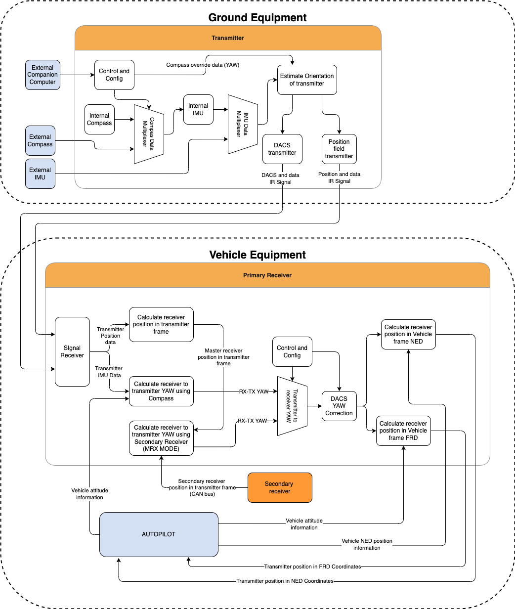
Figure: ULS-XCopter-G2 Functional Description
System Specifications
Common Specification
| Parameter | XCopter-G2 |
|---|---|
| Distance range (m) | 0.1 - 20.0 |
| Working angle (deg) | 60 |
| Data update frequency (Hz) | 20 |
Table: Common System Specifications
Receiver (Onboard Unit)
| Parameter | XCopter-G2 |
|---|---|
| Field of view (deg) | 100 |
| Dimensions (mm) | 20 x 32 x 9 |
| Weight (g) | 10 |
| Power Consumption (W) | 0.3 |
| Voltage supply (V) | 5.0 |
| Interfaces | USB, CAN, UART |
Table: Receiver Specifications
Transmitter (Ground Unit)
| Parameter | XCopter-G2 |
|---|---|
| Field of emitting (deg) | 60 |
| Dimensions (mm) | 50 x 50 x 23 |
| Weight (g) | 45 |
| Power Consumption (W) | 2.4 |
| Voltage supply (V) | 7.5 - 27 |
| Interfaces | USB, CAN, UART |
Table: Transmitter Specifications
Please note that if you use a USB cable to connect the ULS-XCopter-G2 transmitter and power is supplied via this cable, you must ensure that the cable and power supply allows at least 3A. If the power supply or cable does not allow 5V 3A to be delivered to the transmitter, the device may not work properly. In this case it is recommended to use an external power supply of 7.5-24V connected to connector JX1 - External power and control.
Pinout Information
Receiver Pinout
Figure: ULS-XCopter-G2 Receiver Connector
| Pin Number | XCopter-G2 |
|---|---|
| 1 | +5V Input |
| 2 | UART RX |
| 3 | UART TX |
| 4 | CAN H |
| 5 | CAN L |
| 6 | USB D- |
| 7 | USB D+ |
| 8 | UART2 RX |
| 9 | UART2 TX |
| 10 | GND |
Table: Receiver Pinout (JX1)
Transmitter Pinout
Figure: ULS-XCopter-G2 Transmitter Main Connector
| Pin Number | XCopter-G1&G2 |
|---|---|
| 1 | Vcc Input (+7.5V..+27V) |
| 2 | CAN2 H |
| 3 | CAN2 L |
| 4 | UART TX |
| 5 | UART RX |
| 6 | GND |
Table: Transmitter Main Connector Pinout (JX1)
Figure: ULS-XCopter-G2 Transmitter Submodule Connectors
| Pin Number | XCopter-G1&G2 |
|---|---|
| 1 | +5V Output |
| 2 | CAN1 H |
| 3 | CAN1 L |
| 4 | GND |
Table: Transmitter Submodule Connectors Pinout (JC1-JC4)
Mechanical Dimensions
Receiver (G2) Dimensions
Figure: ULS-XCopter-G2 Receiver Dimensions (mm)
Transmitter (G2) Dimensions
Figure: ULS-XCopter-G2 Transmitter Dimensions (mm)
Integration
Ground Unit Installation (Transmitter)

Figure: Transmitter Mechanical Interface
The transmitter can be installed both indoors and outdoors. However, please note that this version of the system is not equipped with protection against moisture and dust. When installing the transmitter, care should be taken to ensure line-of-sight conditions between transmitter and receiver.
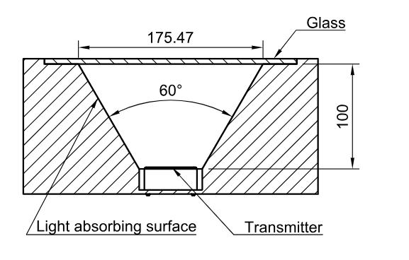
Figure: Transmitter installation variant
The device must be installed on a clean surface to avoid any obstacles. The device must be installed in an open area. There must be no obstacles in the radiation field of the transmitting device. If possible, avoid installing the system near vertical surfaces that can strongly reflect infrared radiation. The 4 holes on the bottom of the device can be used to mount the device. For fastening, use M2 screws, thread depth 2 mm.
It is allowed to install the device under a surface that is optically transparent to infrared radiation by more than 95%. Glass or transparent plastic can act as such a surface. In this case, to increase the coverage of the system at low altitudes, it is recommended to install the transmitter below the level of the platform. This will allow you to expand the coverage of the system to a larger area during touchdown.
Please note, to compensate for the loss of transmitter illumination, you can adjust the illumination power of the transmitter. To do this, place the receiver at a fixed distance from the installed transmitter (recommended 1-2 meters) and adjust the “Device illumination power” of the transmitter until the distance information on the receiver does not correspond to the actual distance. Maximum Correction for “Device illumination power” 110%
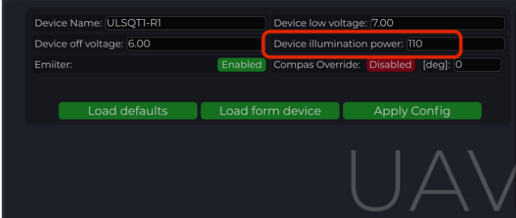
Figure: Transmitter illumination power
After installation, it is recommended to verify the correctness of the compass reading and, if necessary, correct the compass calibration.
Wiring Transmitter
The transmitter only requires power to operate. The transmitter can be powered either via USB-C or via a 6-pin connector located nearby. External compass (IMU) and control data can be sent over UART and CAN protocol. See pinout information of transmitter.
Configure Transmitter in ULS-Tools
To apply any changes, press "Apply Config" button at the bottom of the field.
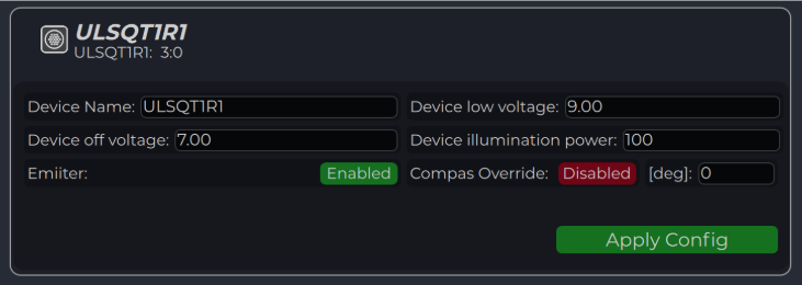
Figure: ULS-Tools Transmitter Configuration Interface
Configuration parameters:
| Parameter | Description |
|---|---|
| Device name | Name of the device displayed in main window |
| Device low voltage | Voltage limit to start indicator flash warning |
| Device off voltage | Voltage limit to disable IR emitters to prevent battery under discharge |
| Device illumination power | Emitters power correction (100 for normal operation) |
| Emitter (enable/disable) | Disable (for configure) or enable emitter |
| Compass Override (enable/disable) [deg] | Enable in case of module installed on fixed platform. The entered value will be used instead of internal compass data in “Compass mode”. In this way, the transmitter must be turned on the corresponding angle, CW to North. |
Table: Transmitter Configuration Parameters
Compass Calibration
This compass is used to calculate an absolute heading of the ground unit. This information is transmitted to the Receiver and used to calculate NED coordinates. To be able to use compass, it needs to be calibrated before.
To calibrate compass:
- Press “Reset calibrations”
- Rotate device in different directions until you get 3 circles on charts (see picture below)
- Press “Apply calibration” & “Apply configuration”
During calibration you can press "Clear chart" to reset previous compass measurements.
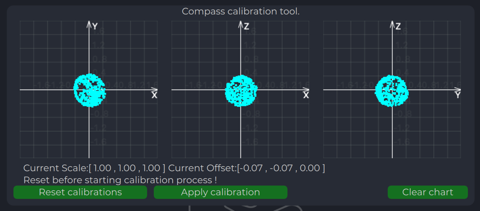
Figure: Compass Chart Before Calibration
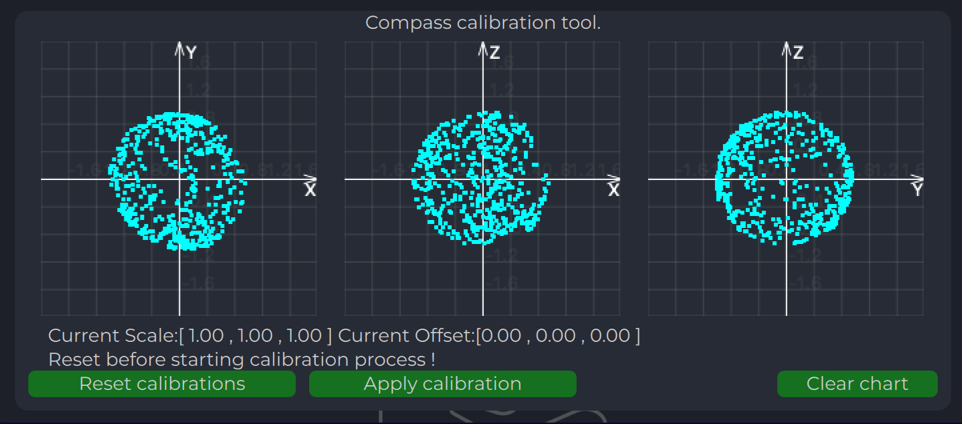
Figure: Compass Chart After Calibration
Emitters Power Indicator
On this field, system shows emitter’s state.
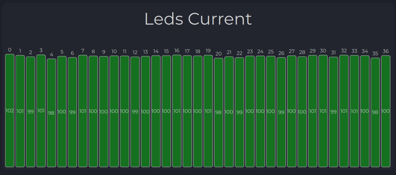
Figure: Emitters Power Indicator
Charts Transmitter
Program displays several parameters of the device on charts:
- IMU data
- Voltage (not valid when powered from USB)
- Temperature data
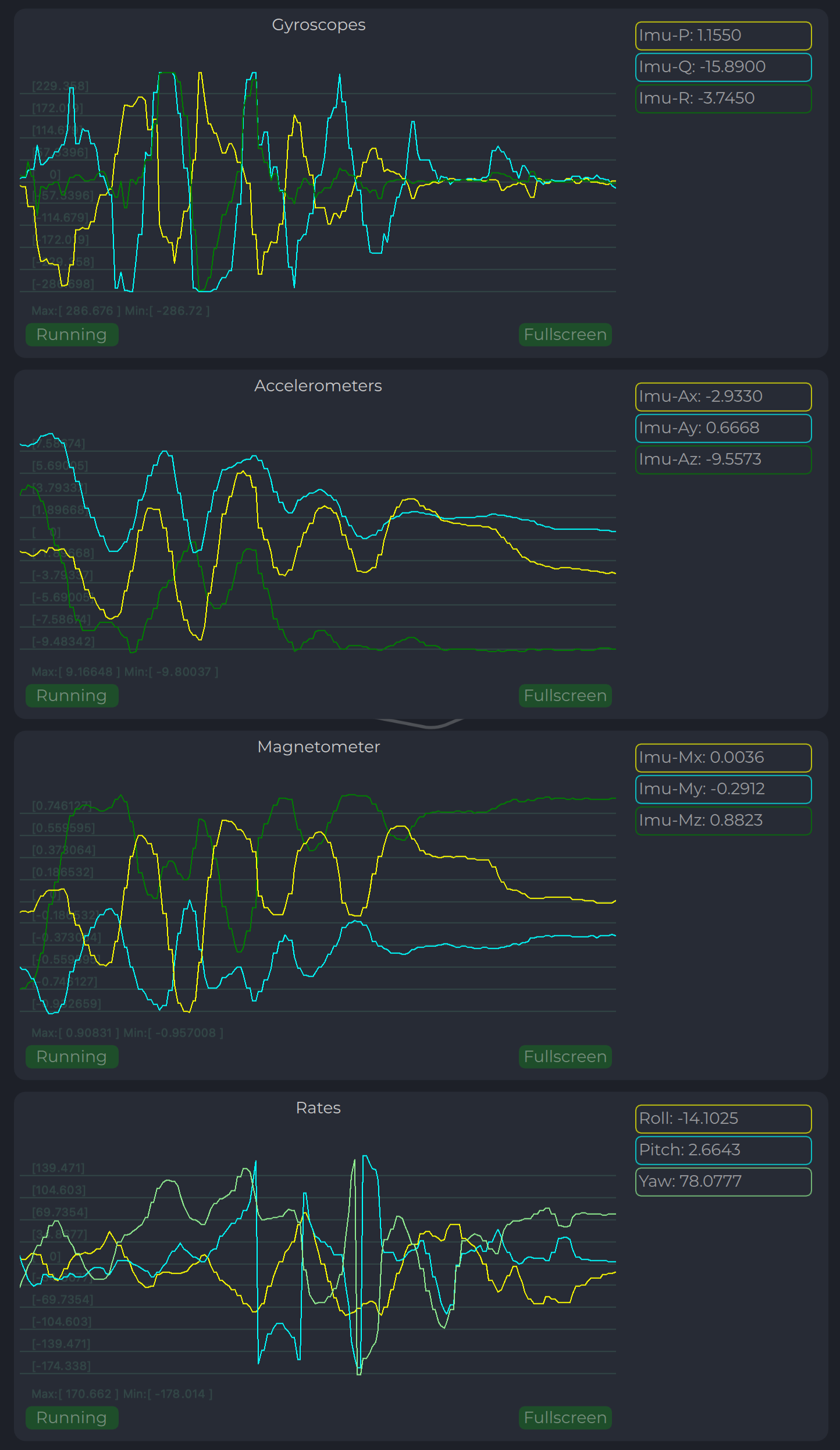
Figure: Transmitter Charts - IMU and Compass Data
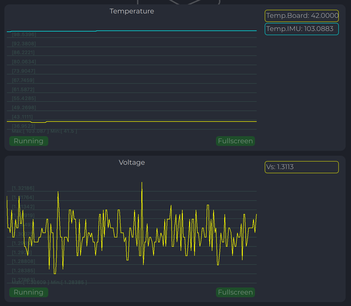
Figure: Transmitter Charts - Voltage and Temperature
LED Indicator
You can check the status of the transmitter by looking at the LED indicator on the transmitter. LED flashes in sequences of colors, so it can flash green-red-off-off or green-off-blue-off.
| Flash Color | Description |
|---|---|
| Green | Normal operation |
| Orange | Low voltage |
| Red | Problem, check device. If it is first in sequence it can be LED malfunctions or power voltage below minimum, second for compass fail detect |
| Blue | Compass OK and device points to the North (brightness of illumination depends on how precise it is pointed to the North) |
Table: LED Indicator Status
On-board Unit Installation (Receiver)
The receiver can be installed both inside and outside the vehicle. However, please note that this version of the system is not equipped with protection against moisture and dust. The orientation of the receiver does not matter - however, when installing the receiver, care should be taken to ensure line-of-sight conditions between the transmitter and receiver throughout the entire field of view of the receiver (100 deg). The receiver sensor zone is indicated in the figure.
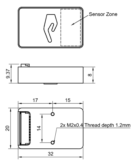
Figure: Receiver Sensor Zone
Once the receiver is installed, enter the appropriate receiver offset information into the configuration.
Wiring Receiver Pixhawk 4 Autopilot Connection Using UART
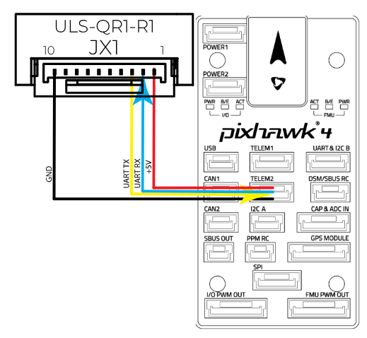
Figure: Receiver Pixhawk 4 Autopilot Connection
Wiring for MultiRX Mode (MRX)
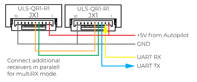
Figure: MultiRX Mode Wiring Diagram
Configure Receiver in ULS-Tools
To apply any changes, press "Apply Config" button at the bottom of the field.
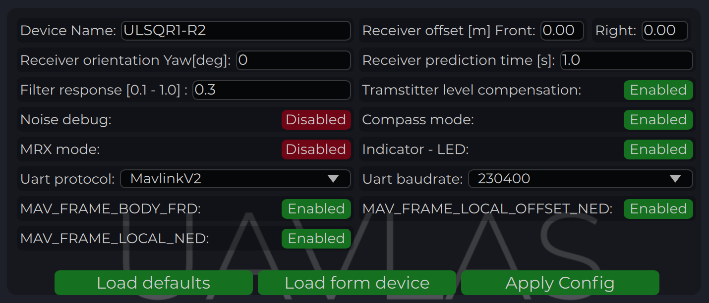
Figure: ULS-Tools Receiver Configuration Interface
Configuration parameters are detailed in the table below.
Status Information Field
In the status display area, you can check the status of the receiver and visualize the position of the receiver relative to the drone. For XCopter-G2, the YAW orientation of the drone received from the DACS system is displayed.
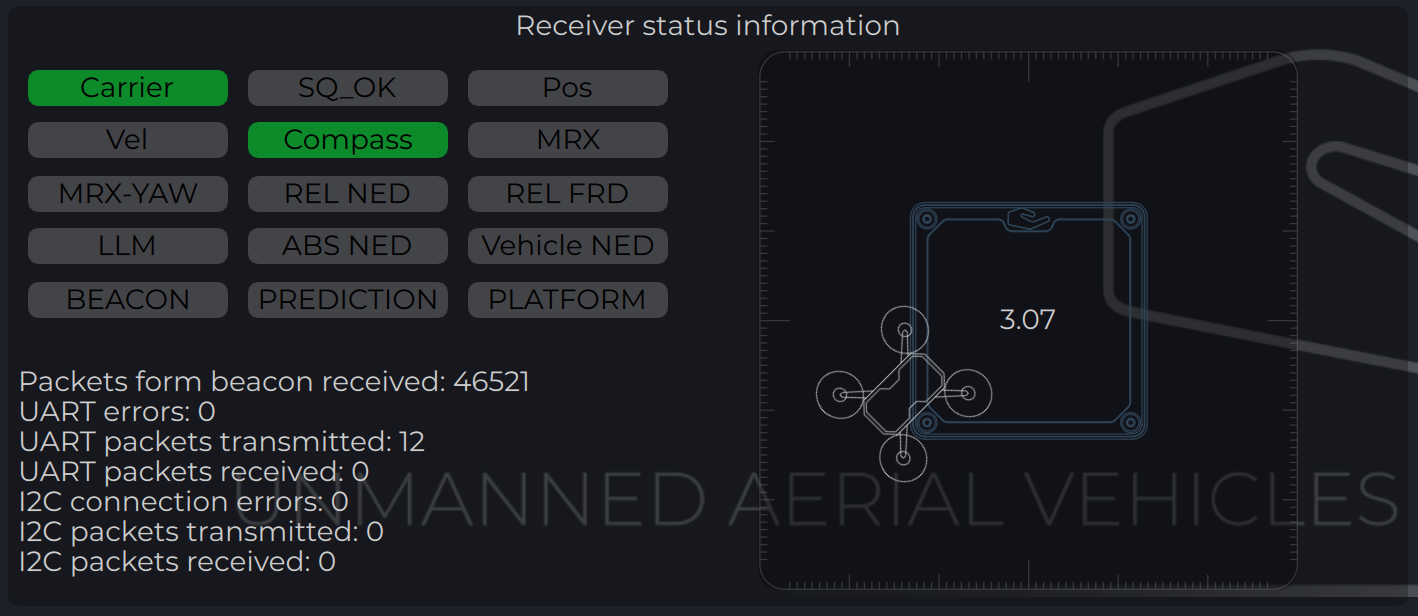
Figure: Receiver Status Information Field
Receiver Charts
Program displays several parameters of the device on charts:
- Angles, Positions in different coordinate systems
- Distance
- Vehicle information (position and velocity)
- Data from Transmitter’s IMU
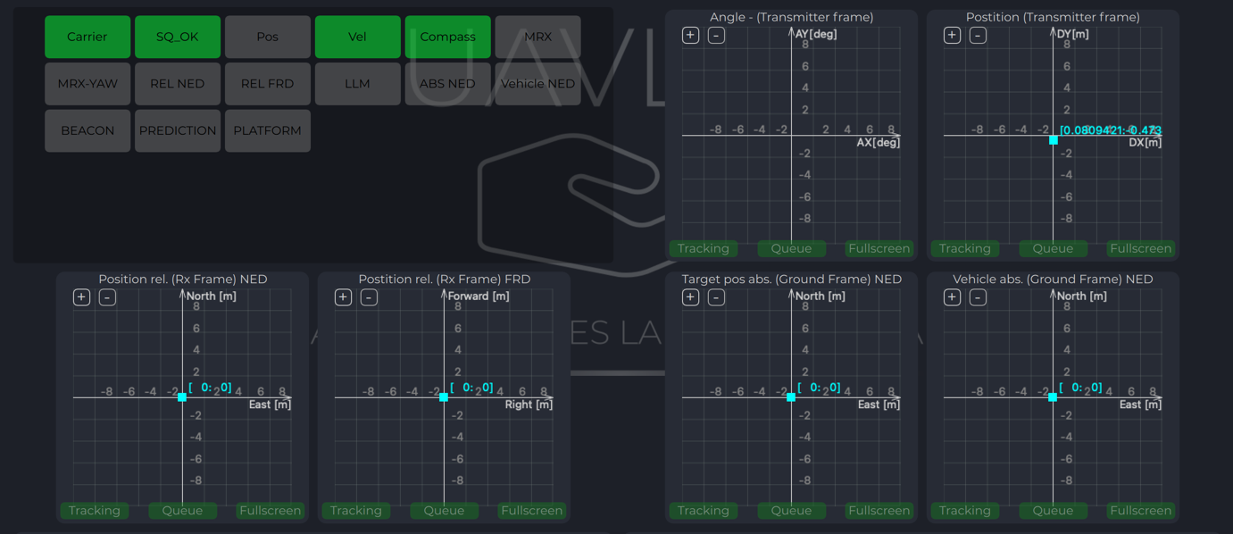
Figure: Receiver Charts - Position and Distance
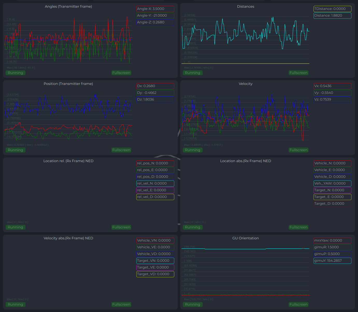
Figure: Receiver Charts - Vehicle Data and IMU
Integration Instructions for Ardupilot Based Systems
Preparing for Integration
Download the latest version of the ULSTools software. It is recommended to connect all sensors to PC and update the firmware for all UAVLAS devices in the system.
Update autopilot with Arducopter latest version.
Configure transmitter.
Configure receiver.
Current version of the system can use MavlinkV2 protocol to communicate with Ardupilot autopilots (for now it supports MAV_FRAME_BODY_FRD).
Example of receiver configuration:
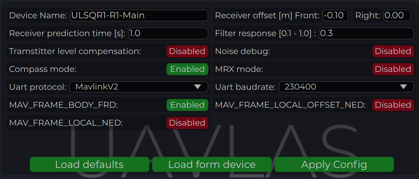
Figure: Receiver Configuration for Ardupilot
Autopilot Configuration
Setup PLND Section
| Param | Value | Comment |
|---|---|---|
| PLND_ENABLED | 1 | Enable precision landing module |
| PLND_TYPE | 1 | Use type = 1 to enable UAVLAS sensor over Companion computer driver |
Table: PLND Section Parameters All other parameters in PLND section defaults or use accordingly to your vehicle set up requirements.
On the picture example configuration provided:
Figure: PLND Configuration Example
It is recommended to test several options of Kalman filter during the test flights (or switch it off) to achieve the best performance.
Set Up Serial Communication in SERIALx Section
| Param | Value | Comment |
|---|---|---|
| SERIAL2_BAUD | 230 | Select baud rate - it needs to be same as in receiver’s configuration |
| SERIAL2_OPTIONS | 0 | Default |
| SERIAL2_PROTOCOL | 2 | MAVlink2 protocol support |
Table: Serial Communication Parameters Set up serial communication messages in SRx Section. Sensor requires some data from autopilot to work in different modes.
| Param | Value | Comment |
|---|---|---|
| SR2_EXTRA1 (or MAV2_EXTRA1) | 20 | Stream Attitude information (20Hz) (YAW Orientation is required for sensor in compass mode) |
| SR2_POSITION (or MAV2_POSITION) | 20 | Optional - Stream Vehicle position (20Hz) (LOCAL_POSITION_NED is required for sensor to provide LOCAL position for the target) |
Table: Stream Rate Parameters
Check Setup
If all settings are done correctly, autopilot has GPS data and receiver is in the field of view of the transmitter, you can find LANDING_TARGET message in mavlink inspector (a screenshot from Mission Planner):
Figure: LANDING_TARGET Message in MAVLink Inspector
Setup Precision Loiter Mode
To enable precision loiter mode you need to attach any unused switch to PrecLoiter option see picture below:
Figure: PrecLoiter Switch Configuration
Try to use this switch and you must get messages: “PrecLoiter: LOW” and “PrecLoiter: HIGH”. After test flight above target check telemetry - you will find PL data contains offsets from landing target.
Figure: Telemetry Data with PL Offsets
PID Tuning
In case of oscillations and other issues at landing stage, please check PID parameters of Ardupilot.
It is recommended to check the Position XY, Velocity XY and Loiter speed parameters in “Extended tuning” section to achieve the best performance.
Figure: Extended Tuning Parameters
For example, settings Velocity XY P = 0.8, I = 0.2, and D = 0.6 works well for some of our customers
It is recommended to start testing PIDs and precision system performance in "Precision Loiter" mode. It uses some algorithms and settings in precision landing.
For additional information, see Ardupilot manual.
Integration Instructions for PX4 Based Systems
Preparing for Integration
Download the latest version of the ULSTools software. It is recommended to connect all sensors to PC and update the firmware for all UAVLAS devices in the system.
Update autopilot with PX4 latest version.
Configure transmitter.
Configure receiver.
Current version of the system can use MavlinkV2 protocol to communicate with PX4 autopilots (for now it supports MAV_FRAME_LOCAL_NED).
Example of receiver configuration:
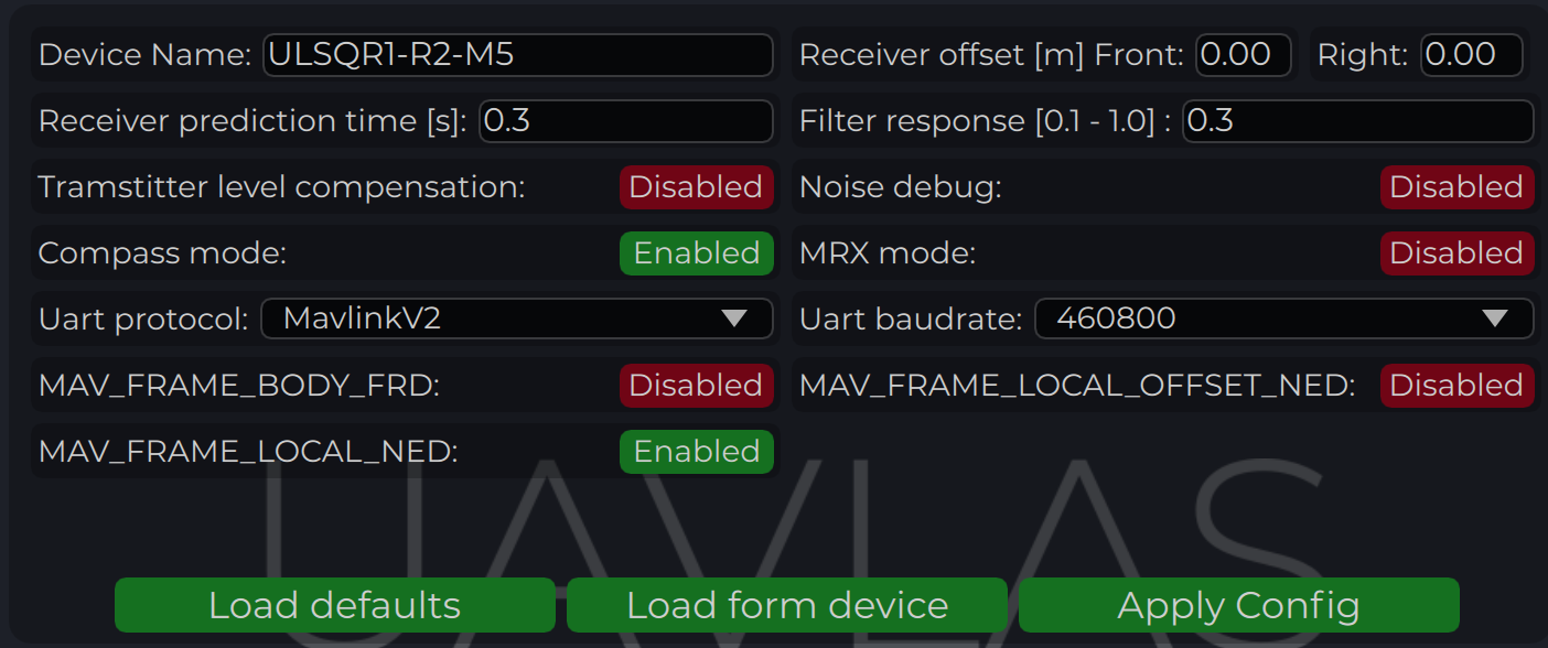
Figure: Receiver Configuration for PX4
Configure PX4 Autopilot
Values are provided as example (in our case, Pixhawk4-mini AP):
| PX4 Parameter | Value |
|---|---|
| MAV_1_CONFIG | TELEM/SERIAL4 (require reboot to set next params) |
| MAV_1_FORWARD | Enabled |
| MAV_1_MODE | Onboard |
| SER_TEL4_BAUD | 460800_8N1 (It needs to be corresponding to the setting of UART in Receiver ULS-QR1-R1 connected to PX4 AP) |
Table: PX4 Configuration Parameters
Running and Testing
After configuration and wiring, power up drone and transmitter. On QGround Control, go “Analyze Tools” -> MAVLINK Inspector. Check LANDING_TARGET MAVLINK message.
In case the vehicle provides LOCAL_POSITION_NED message to UAVLAS system, and it hovers over beacon, you get “position_valid = 1” in LANDING_TARGET.
To perform precision landing, you need to create a flight plan and enable Precision Landing option on the landing point.
LANDING_TARGET may be unavailable in case of connection over USB. So, use telemetry channel (uart modem etc.) to connect drone to the QGroundControl.
Figure: LANDING_TARGET in QGround Control
Troubleshooting
Before Starting, Check
- You are using latest version of ULS-Tools, latest firmware on ULS-XCOPTER transmitter and receiver, and latest Ardupilot (PX4) firmware.
No MAVLink Message
ULS-XCopter transmitter is switched on and receiver is in field of view of transmitter.
Red light on receiver flashes fast (> 5 times per second). If it flashes 2 times per second it means that transmitter is not switched on, or not in field of view. If it does not flash - check power.
Check Serial settings on AP params and on receiver. Be sure you have set EXTRA params for corresponding serial port on AP.
Check wiring power and RX, TX (see pinouts and wiring diagram).
Check on receiver that MAV_FRAME_BODY_FRD (MAV_FRAME_LOCAL_NED) is enabled.
Not Holding in Precision Loiter Mode But MAVLink Message OK
- Check that you setup Precision loiter mode on AP.
Circular Motions During Landing
Check compass calibration on ground unit.
Check compass calibration on AP.
Check magnetic interference on ground.
Use compass override mode to debug landing.
Check precision landing PID settings.
The Landing is Not Precise Enough
Check the position control PID settings of AP.
For Ardupilot check Kalman filter settings.
Check filter smoothness param on receiver.
Check trajectory Jerk settings on AP.
Safety Information
- Do not expose the system to moisture or dust without proper protection
- Ensure adequate power supply (minimum 3A for USB connection)
- Do not operate beyond specified temperature range
Change Control
All changes to this document must be reviewed and approved by the relevant technical leads and stakeholders.
11 - ULS-XSpot
End of Production
11.1 - ULS-XSpot Datasheet
Datasheet ULSDC-PBDS231125, version 1.0.1
ULSDC-PBDS231125 · version 1.0.1 · issued November 23, 2025
The numbered PDF is the controlled copy: download it from the portal.
Introduction
Purpose
The purpose of this datasheet is to provide comprehensive technical information about the ULS-XSpot System family, specifically designed for tethered drone operations. This includes specifications, performance characteristics, and detailed descriptions of system components, such as the tether-compatible transmitter and receivers. By outlining the interfaces between these components, the datasheet aims to facilitate seamless integration and operation for system engineers, integrators, and developers working with tethered drone systems.
Scope
This document is intended for use by system engineers, integrators, and developers working with ULS-XSpot systems in tethered drone applications. It provides detailed information on the system, with special emphasis on tethered drone operation requirements and the 50-meter working range.
Key Differences from ULS-Heli-G2
The ULS-XSpot system is optimized for tethered drone operations and features the following key differences:
- Tethered Design: Transmitter features a center hole for tether cable passage, enabling integration with tethered drone power and data systems
- Simplified Optics: Standard IR optical link without DACS technology, over the same 50-meter working distance as ULS-Heli-G2
- Application Focus: Specifically designed for stationary or slow-moving tethered drone operations with continuous power availability
System Base Components
Transmitter (Ground Unit - Tethered Design)
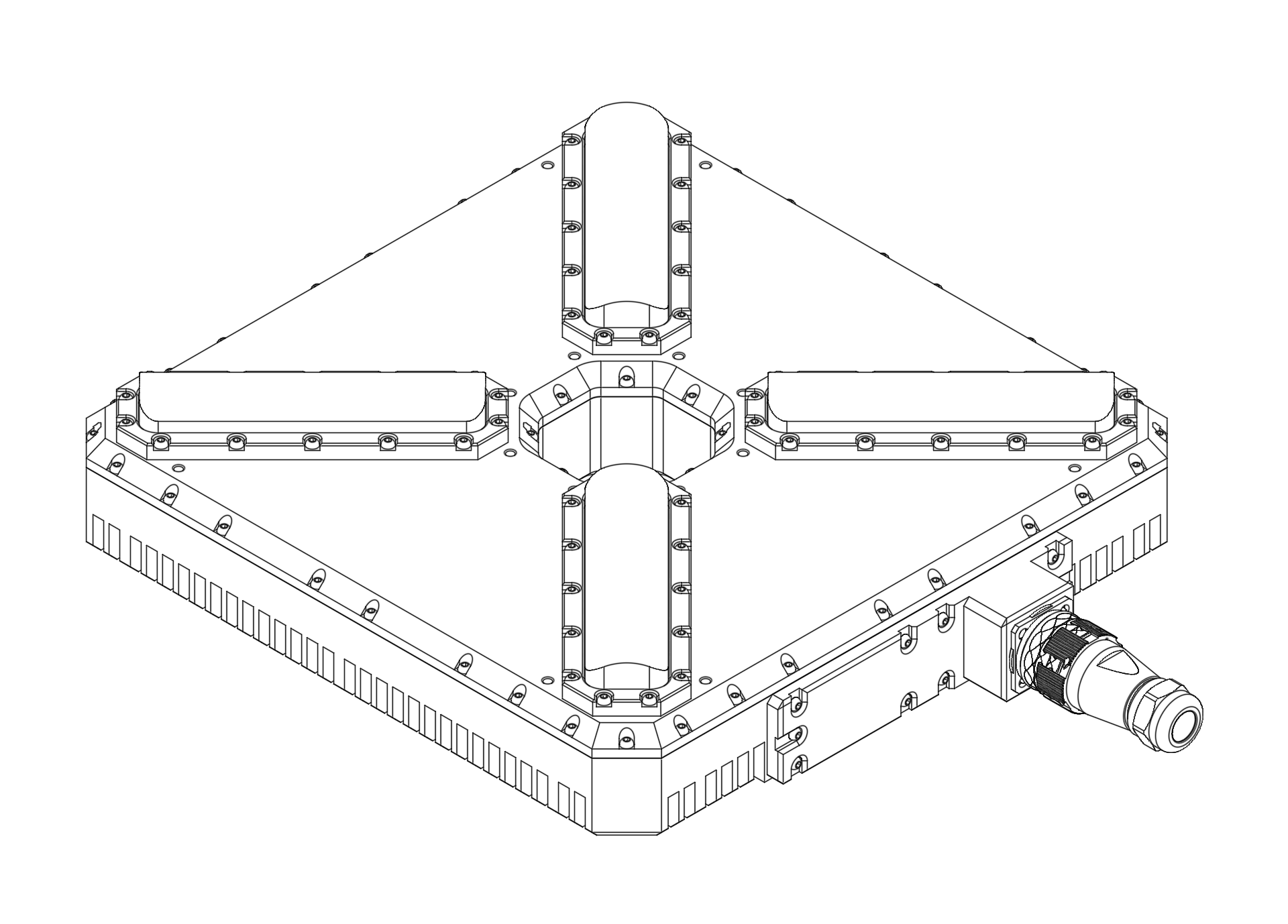
Figure: ULS-XSpot Transmitter with Center Tether Hole The ULS-XSpot transmitter is specifically designed for tethered drone systems. It features a center hole for tether passage, allowing the drone’s power and data cable to pass through while maintaining optical positioning capabilities. The transmitter is placed on the ground (platform, moving object) and emits a signal in the Infrared range, serving as a positioning beacon for tethered drone landing and station-keeping.
The primary function of the transmitter is to continuously send out a coded signal that can be detected and interpreted by the receiver unit onboard the tethered copter. This signal contains critical information needed for the operation of the system, such as positional data and status. The tethered design allows for extended flight duration while maintaining precision positioning.
Key Features:
- Center hole for tether cable passage (integrated tether management)
- Working range: 50 meters working distance
- Optimized for tethered drone operations
- Continuous power available via tether connection
Receiver (Onboard Unit)
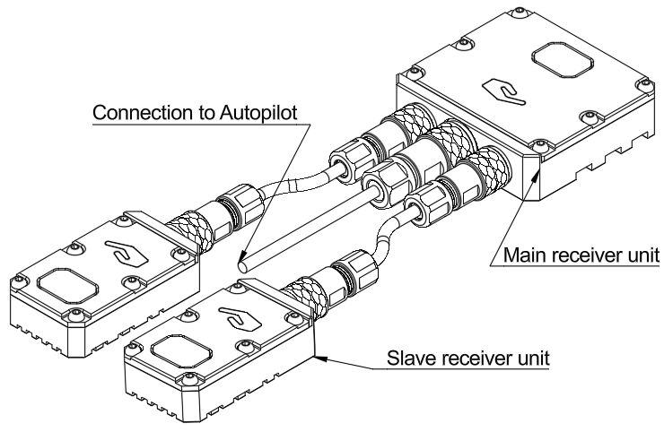
Figure: ULS-XSpot Receiver The receiver is a device that is placed on board the tethered aircraft. The receiver decodes the IR signal to derive flight information such as positional coordinates, real-time transmitter status updates, and positioning guidance. It interprets the data to navigate accurately and ensure the drone maintains its position relative to the ground station. It provides feedback to autopilot systems, such as Ardupilot and PX4, to adjust the flight parameters as needed for optimal station-keeping, landing, or hovering operations while connected to the tether.
Key Features:
- Compatible with tethered drone configurations
- Real-time position feedback for station-keeping
- Seamless integration with tether management systems
Part Numbering
| Part Number | Description |
|---|---|
| ULS-XSPOT | System set with 3 receivers for tethered drone systems. |
| ULSDV-XS-TX | Transmitter unit with center tether hole. |
| ULSDV-XS-RXM | Master receiver unit. |
| ULSDV-XS-RXS | Slave receiver unit. |
| SA610/P4IB | 4 Pin Connector for receiver. Manufacturer Weipu. |
| SA810/P8IIB | 8 Pin Connector for receiver. Manufacturer Weipu. |
| SA1610/P10IIB-1 | 10 Pin Connector for transmitter. Manufacturer Weipu. |
Table: Part Numbering
System Specification
| Parameter | Value |
|---|---|
| Distance range m.: | 50.0 |
| Working angle (deg): | 60 |
| Data update frequency (Hz): | 20 |
| Technology: | Standard IR Optical (No DACS) |
Table: Common Specification
| Parameter | Value |
|---|---|
| Field of view (deg): | 90 |
| Dimensions mm : | 46x26x12 |
| Weight g.: | 40 |
| Power Consumption (W): | 3 |
| Voltage supply (V): | 5 |
| Interfaces: | USB, CAN, UART |
Table: Receiver (Slave) Specifications
| Parameter | Value |
|---|---|
| Field of view (deg): | 90 |
| Dimensions mm : | 50x50x14 |
| Weight g. : | 60 |
| Power Consumption (W): | 3 |
| Voltage supply (V): | 5 |
| Interfaces: | USB, CAN, UART |
Table: Receiver (Master) Specifications
| Parameter | Value |
|---|---|
| Field of emitting (deg): | 35 |
| Dimensions mm. : | 290x215x48 |
| Weight g.: | 4100 |
| Power Consumption (W): | 10 |
| Voltage supply (V): | 22.0-26.0 |
| Interfaces : | USB, CAN, UART |
| Special Features: | Center hole for tether passage |
Table: Transmitter (Ground) Specifications - Tethered Design
Pinout Information
Transmitter Pinout
| Pin | Function |
|---|---|
| 1 | Vin +18V – +28V |
| 2 | RS422A |
| 3 | RS422B |
| 4 | RS422Y |
| 5 | RS422Z |
| 6 | CAN-L |
| 7 | CAN-H |
| 8 | USB-D- |
| 9 | USB-D+ |
| 10 | GND |
Table: Transmitter 10 Pin Connector Pinout
Please DO NOT "HOT-PLUG" Transmitter cable. Apply power on transmitter only when connector connected to transmitter.
Please check pin numbers on connector.
Incorrect wiring or connection under voltage can damage the device and USB interface of connected PC !
Special Note for ULS-XSpot: The transmitter includes a center hole for tether cable passage. Ensure tether cable routing does not obstruct the IR emission pattern.
Receiver Pinout
| Pin | Function |
|---|---|
| 1 | Vin (+5V) |
| 2 | CANH |
| 3 | CANL |
| 4 | GND |
Table: 4 Pin Connector Pinout
| Pin | Function |
|---|---|
| 1 | Vin (+5V) |
| 2 | CANH |
| 3 | CANL |
| 4 | UART_TX (OUT) |
| 5 | UART_RX(IN) |
| 6 | USB_D- |
| 7 | USB_D+ |
| 8 | GND |
Table: 8 Pin Connector Pinout
Mechanical Dimensions
Figure: Slave Receiver Mechanical Dimensions
Figure: Master Receiver Mechanical Dimensions
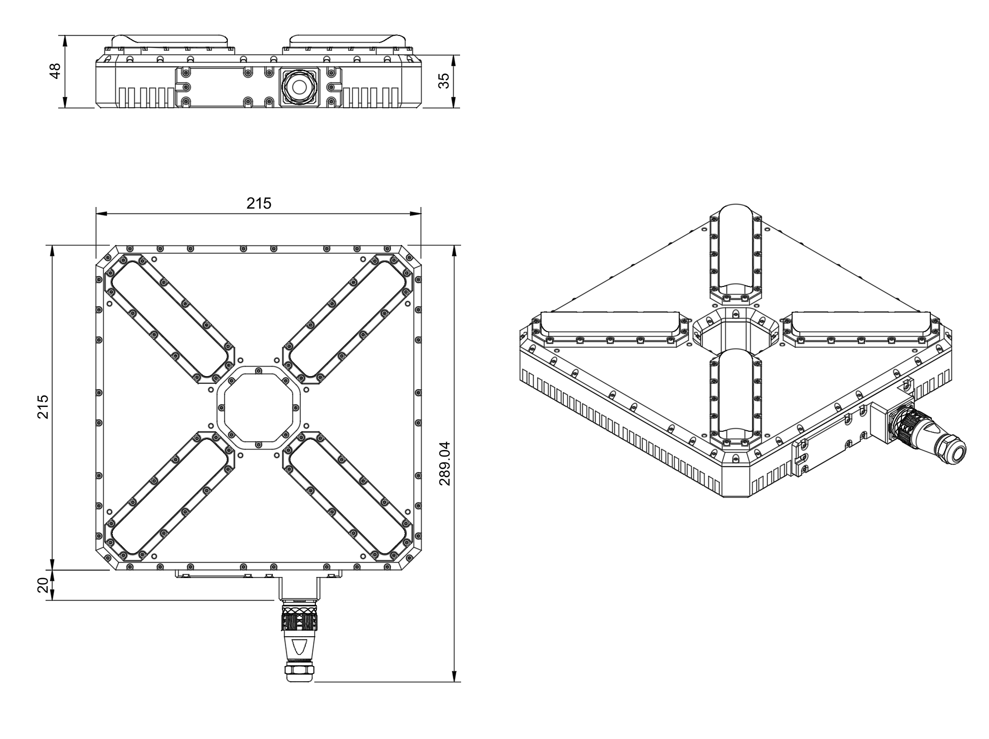
Figure: Transmitter Mechanical Dimensions with Center Tether Hole
Note: The transmitter features a center hole designed for tether cable passage, enabling integration with tethered drone power and data systems.
Packaging Information
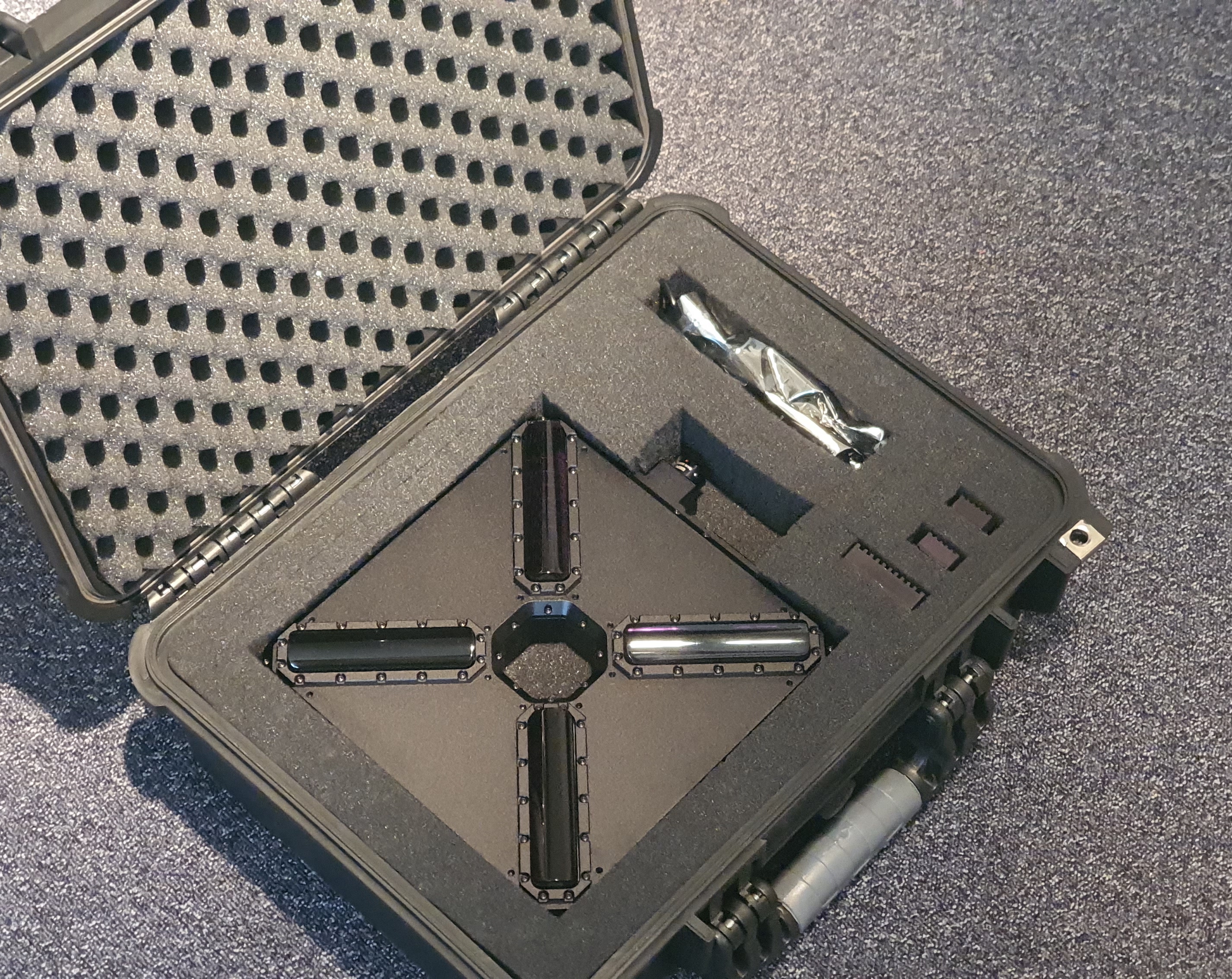
Figure: ULS-XSpot System Package
The ULS-XSpot system is packaged in a protective hard case designed for field deployment in tethered drone operations.
Package Contents
- 1x Transmitter unit (with center tether hole)
- 1x Master receiver unit
- 2x Slave receiver units
- Connection cables
- Mounting hardware
- Quick start guide
- USB configuration cable
Package Specifications
| Parameter | Value |
|---|---|
| Case Type | Hard protective case |
| Dimensions (LxWxH) | Approx. 450 x 350 x 200 mm |
| Weight (with equipment) | Approx. 6 kg |
Table: Package Specifications
Environmental Conditions - Industrial Grade
Equipment is designed to operate reliably in demanding environmental conditions typical of aerospace, industrial automation, and outdoor applications.
Operating Temperature Range
- Standard operating range: -20°C to +55°C
- Covers most industrial and outdoor applications
- Reliable performance across temperature extremes
- No performance degradation within specified range
Humidity Tolerance
- Relative humidity: Up to 70% (non-condensing)
- Protected against moisture in typical operating conditions
- Suitable for outdoor and semi-protected installations
- Condensation prevention through sealed design
Ingress Protection
- IP67 rated (Dust tight and water immersion resistant)
- 6 - Complete protection against dust ingress
- 7 - Protected against temporary immersion in water (up to 1 meter depth for 30 minutes)
- Suitable for harsh industrial environments
- Protected against rain, splashing, and temporary submersion
- Dust-tight sealing for contaminated environments
Storage Conditions
- Storage temperature: -40°C to +70°C
- Relative humidity: Up to 95% (non-condensing)
- Long-term storage in industrial facilities
Operational Environment Standards
- Designed to meet industrial equipment requirements
- Suitable for UAV/drone applications
- Outdoor installation capable
- Protected against:
- Dust and particulate matter
- Water spray and rain
- Temporary water immersion
- Temperature fluctuations
- High humidity
Tethered Operation Guidelines
System Integration
The ULS-XSpot system is specifically designed to work with tethered drone platforms. Key integration considerations include:
- Tether Routing: Route the tether cable through the center hole of the transmitter
- Clearance: Maintain minimum 10cm clearance around transmitter for optimal IR propagation
- Cable Management: Secure tether to prevent interference with optical path
- Ground Station Setup: Position transmitter at the tether connection point for optimal positioning reference
Advantages for Tethered Drones
- Extended Flight Time: Continuous power via tether enables unlimited operation duration
- Stable Reference: Tether provides additional stability reference for position control
- Simplified Design: Center hole design integrates cleanly with tether management systems
- Enhanced Safety: Physical tether connection adds redundancy to positioning system
- Weather Resilience: Extended operation capability in various weather conditions with continuous power
Change Control
All changes to this document must be reviewed and approved by the relevant technical leads and stakeholders
11.2 - ULS-XSpot Interface Control Document
Interface Control Document ULSDC-PBICD231125, version 1.0.2
ULSDC-PBICD231125 · version 1.0.2 · issued November 23, 2025
The numbered PDF is the controlled copy: download it from the portal.
Introduction
Purpose
This document outlines the interfaces between the ULS-XSpot system components, including the tether-compatible transmitter, receiver, and autopilot systems (Ardupilot, PX4, and similar). The ULS-XSpot is specifically designed for tethered drone operations with a 50-meter working range.
Scope
This document is intended for use by system engineers, integrators, and developers working with ULS-XSpot systems in tethered drone applications. It provides detailed information on the interfaces between the system components, ensuring seamless integration and operation with tether management systems.
Key Features for Tethered Operations
- Tether-Compatible Design: Center hole in transmitter for cable passage
- Working Range: 50-meter working distance
- Standard IR Optical: No DACS technology required
- Continuous Operation: Designed for 24/7 operation with tethered power
System Components
Transmitter (Ground Unit - Tethered Design)
Figure: ULS-XSpot Transmitter with Center Tether Hole The ULS-XSpot transmitter is specifically designed for tethered drone systems. It features a center hole for tether passage, allowing the drone’s power and data cable to pass through while maintaining optical positioning capabilities. The transmitter is placed on the ground (platform, moving object) and emits a signal in the Infrared range, serving as a positioning beacon for tethered drone landing and station-keeping.
The primary function of the transmitter is to continuously send out a coded signal that can be detected and interpreted by the receiver unit onboard the tethered copter. This signal contains critical information needed for the operation of the system, such as positional data and status. The tethered design allows for extended flight duration while maintaining precision positioning.
Key Features:
- Center hole for tether cable passage (integrated tether management)
- Working range: 50 meters working distance
- Optimized for tethered drone operations
- Continuous power available via tether connection
Receiver (Onboard Unit)
Figure: ULS-XSpot Receiver The receiver is a device that is placed on board the tethered aircraft. The receiver decodes the IR signal to derive flight information such as positional coordinates, real-time transmitter status updates, and positioning guidance. It interprets the data to navigate accurately and ensure the drone maintains its position relative to the ground station. It provides feedback to autopilot systems, such as Ardupilot and PX4, to adjust the flight parameters as needed for optimal station-keeping, landing, or hovering operations while connected to the tether.
Key Features:
- Compatible with tethered drone configurations
- Real-time position feedback for station-keeping
- Seamless integration with tether management systems
Interface Overview
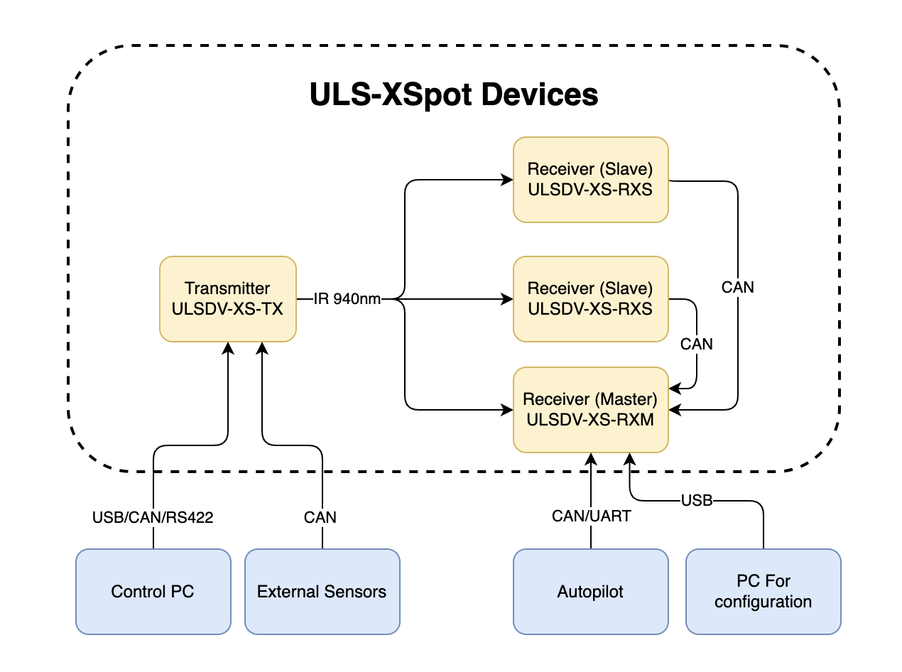
Figure: ULS-XSpot System Interfaces Overview
Note: The ULS-XSpot uses the same interface architecture as ULS-Heli-G2, with the addition of tether-compatible mechanical design.
Transmitter to Control PC Interface (External Sensors)
The transmitter can be connected to a control PC or external equipment for configuration, status monitoring, and data exchange.
Data Types
- Status information
- Control signals
- Transmitter configuration
- External IMU/COMPASS data
Connection Types
- CAN Bus - For network communication
- USB - For configuration and firmware updates
- RS422 - For serial communication with external sensors
Transmitter Pinout
| Pin | Function |
|---|---|
| 1 | Vin +18V – +28V |
| 2 | RS422A |
| 3 | RS422B |
| 4 | RS422Y |
| 5 | RS422Z |
| 6 | CAN-L |
| 7 | CAN-H |
| 8 | USB-D- |
| 9 | USB-D+ |
| 10 | GND |
Table: Transmitter 10 Pin Connector Pinout
Please DO NOT "HOT-PLUG" Transmitter cable. Apply power on transmitter only when connector connected to transmitter.
Please check pin numbers on connector.
Incorrect wiring or connection under voltage can damage the device and USB interface of connected PC !
Tethered System Note: When routing tether cable through the center hole, ensure the cable does not interfere with connector access or IR emission pattern.
Transmitter to Receiver Interface
The transmitter and receiver use an optical interface to exchange data. Transmission uses IR emission at 940 nanometers. Data transmission is only in the direction from the transmitter to the receiver.
Optical Range and Performance
| Parameter | ULS-XSpot | ULS-Heli-G2 | Notes |
|---|---|---|---|
| Maximum Range | 50m | 50m | Same range |
| Working Angle | 60° | 60° | Emission cone |
| Technology | Standard IR | IR + DACS | Simplified for tethered use |
| Update Rate | 20Hz | 20Hz | Same performance |
Table: Optical Interface Comparison
Data Types
- Position encoded
- Status encoded data (Transmitter orientation and instructions)
Connection Type
- Optical IR 940nm - Infrared optical link
Tethered Operation: The 50-meter range covers typical tethered drone operating heights. Tether provides stable reference, reducing positioning complexity compared to free-flight applications.
Receiver to Autopilot and Receiver to PC Interfaces
Data Types
- MAVLink messages
- ULS-Blitz frames
- ASCII protocol
Connection Types
- UART - Serial communication with autopilot
- CAN - Network communication
- USB - Direct PC connection
Receiver Pinout
| Pin | Function |
|---|---|
| 1 | Vin (+5V) |
| 2 | CANH |
| 3 | CANL |
| 4 | GND |
Table: 4 Pin Connector Pinout
| Pin | Function |
|---|---|
| 1 | Vin (+5V) |
| 2 | CANH |
| 3 | CANL |
| 4 | UART_TX (OUT) |
| 5 | UART_RX(IN) |
| 6 | USB_D- |
| 7 | USB_D+ |
| 8 | GND |
Table: 8 Pin Connector Pinout
Powering Interfaces
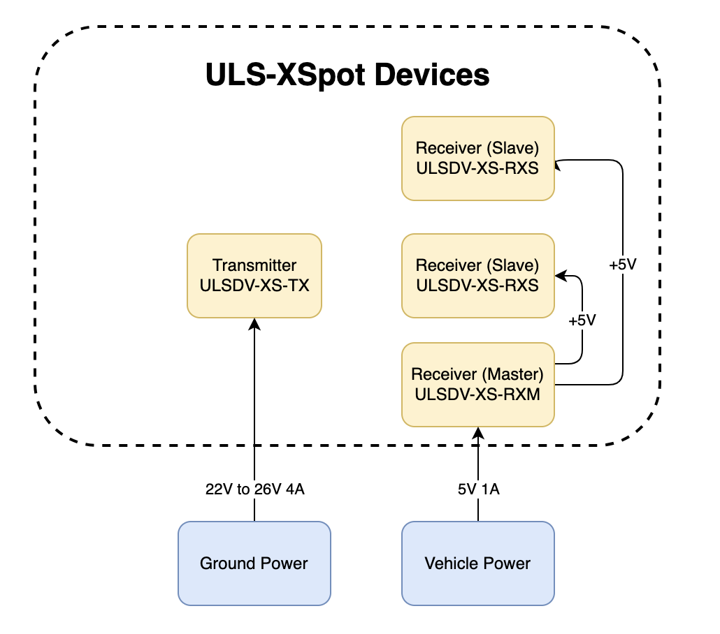
Figure: Power Distribution and Connections
Transmitter Electrical Characteristics
| Parameter | Value | Unit | Notes |
|---|---|---|---|
| Supply Voltage | 22.0 - 26.0 | V | Nominal 24V |
| Supply Current | 4 | A | Peak |
| Power Consumption | 18.1 | W | Typical |
Table: Transmitter Electrical Specifications Tethered System Power: Transmitter can be continuously powered from ground station power supply. Consider tether voltage drop when sizing power system for long tether runs.
Receiver Electrical Characteristics
| Parameter | Value | Unit | Notes |
|---|---|---|---|
| Supply Voltage | 5.0 | V | From flight controller or tether |
| Supply Current | 1 | A | Peak |
| Power Consumption | 3 | W | Typical |
Table: Receiver Electrical Specifications Tethered Power Option: Receiver can be powered from flight controller or directly from tether power distribution system.
Functional Diagram
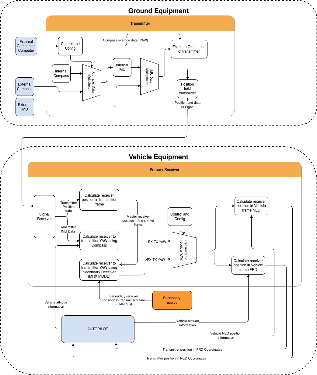
Figure: Functional description of the system
Functional Interfaces
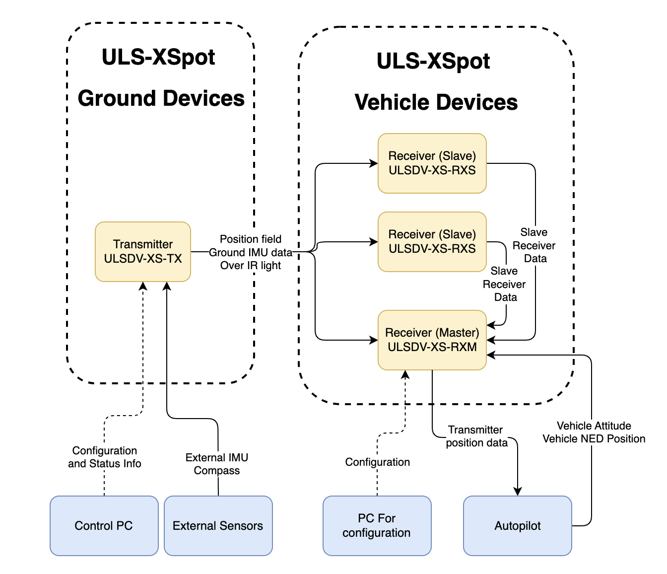
Figure: Data Flow and Functional Interfaces
Data Exchange
The ULS-XSpot system implements several data exchange mechanisms optimized for tethered operations:
Control PC Functions:
- Configure and view status of transmitter
- Set configuration of receivers
- Send control signals (On/off, compass override information)
- Monitor tethered operation parameters
External Equipment:
- External IMU/Compass equipment can be used to override internal IMU/compass information
- Tether management system integration for position reference
Receiver Functions:
- Accept data from transmitter over IR signal (position field information and ground unit IMU data)
- Accept NED and Attitude information from autopilot to convert coordinate system
- Multiple receivers can communicate to calculate vehicle orientation (YAW)
- Send position offset data to autopilot
- Support for tethered flight modes and station-keeping
Tethered System Integration
Ground Station Interface:
- Power distribution to transmitter via ground power supply
- Data connection for configuration and monitoring
- Tether management system coordination
Aircraft Interface:
- Position data from ULS-XSpot receiver to autopilot
- Tether tension and status monitoring (external system)
- Coordinated flight control for tethered operations
Mechanical Interfaces
Figure: Slave Receiver Mechanical Dimensions
Figure: Master Receiver Mechanical Dimensions
Figure: Transmitter Mechanical Dimensions with Center Tether Hole
Note: The transmitter features a center hole designed for tether cable passage, enabling integration with tethered drone power and data systems.
Transmitter Mounting with Tether
The transmitter features a center hole for tether passage. Key mounting considerations:
- Use 16 mounting holes to secure transmitter to platform
- Route tether cable through center hole before mounting
- Ensure tether has adequate strain relief above and below transmitter
- Maintain 10cm minimum clearance around transmitter for IR emission
- Verify tether routing does not obstruct 60° emission cone
Receiver Mounting
Both master and slave receivers have mounting provisions for secure installation on tethered aircraft. 3D models of the receivers can be provided upon request.
Tethered Aircraft Considerations:
- Position receivers to avoid tether shadow/obstruction
- Consider tether dynamics in receiver placement
- Maintain clear line-of-sight to ground transmitter
Communication Protocols
Overview
The protocol used by devices for configuration is proprietary and is described in other documents. However, the protocol implements the possibility of transmitting messages (Blitz messages) that can be used by the user to control the device and obtain information. These messages are universal, and the format describes the data that is transmitted by various devices in our system connected to a single network.
Use CMD=6 to send Blitz messages.
In this document, the CAN protocol is specified. RS485 is used to implement custom protocols that can be defined in the future.
CAN Bus Protocol Frame Format
flowchart LR
  A[Sender Device] --> B[GLOBAL]
  B --> C[CMD = 6]
  C --> D[ID]
  D --> E[dsn_lid]
  E --> F[msg_id]
  F --> G[Blitz Payload data <= 8 bytes]
  G --> H[Receiver Device]
The CAN protocol uses the following frame structure:
| Field | Description |
|---|---|
| GLOBAL | Flag used to send packets over several local networks |
| CMD | Command field (Use CMD=6 to send Blitz messages) |
| ID | Packet sender ID (local id src_lid for local packets and device id for global packets src_did) |
| dsn_lid | Destination local ID address |
| msg_id | Message ID used to identify Blitz packet types |
Table: CAN Protocol Frame Fields
Status Bit Definitions
Most messages include a status byte with the following bit definitions:
| Bit | Flag | Description |
|---|---|---|
| 0 | ULS_STATUS_RX_CARRIER_OK | IR signal detected |
| 1 | ULS_STATUS_RX_SQ_OK | Signal quality OK |
| 2 | ULS_STATUS_RX_POS_OK | Position estimated |
| 3 | ULS_STATUS_RX_VEL_OK | Velocity estimated |
| 4 | ULS_STATUS_RX_GU_IMU_OK | Ground Unit IMU OK |
| 5 | ULS_STATUS_RX_MRX_OK | MRX message received (secondary receiver) |
| 6 | ULS_STATUS_RX_MRXDATA_OK | MRX Yaw and Distance calculated OK |
Table: Status Bit Definitions
Common Data Structure
Blitz Common Data Structure
Structure: __blitz_common_data_struct
| Field | Type | Description |
|---|---|---|
src_lid | uint8_t | Source logical ID |
msg_id | uint16_t | Message ID (see message types below) |
data | union | Message-specific data (8 bytes max) |
Table: Blitz Common Data Structure The union contains all possible message structures:
xcg1_rx_raw_measurmetrx_raw_measurmetrx_pos_in_tx_framerx_mrxrx_dacs
Usage: Universal container for all ULS Blitz message types.
Implementation Notes
- Packed Structures: All structures use
__attribute__((packed))to ensure no padding bytes are added by the compiler. - Endianness: The protocol assumes little-endian byte order for multi-byte fields.
- Angular Precision: Angular measurements use 16-bit signed integers with specific scaling factors for different ranges.
- Distance Units: Distance measurements may use different units (cm, 10cm increments) depending on the message type.
Message Types
XCG1 Raw Measurement (0x0010)
Message ID: ULS_BLITZ_MSG_ID_XCG1_RX_RAW_MEASURMENT (0x0010)
Structure: __uls_blitz_xcg1_rx_raw_measurmet
| Field | Type | Description |
|---|---|---|
status | uint8_t | Status bits (see Status Bit Definitions above) |
d | uint8_t | Distance in 10 cm increments |
aX | int16_t | Angular information X-axis, proportional [-30000 = -30°, +30000 = +30°] |
aY | int16_t | Angular information Y-axis, proportional [-30000 = -30°, +30000 = +30°] |
oF | int8_t | Sensor offset Forward in cm |
oR | int8_t | Sensor offset Right in cm |
Table: XCG1 Raw Measurement Message Format Purpose: Legacy raw measurement data for XCG1 systems with limited angular range.
Raw Measurement (0x0011)
Message ID: ULS_BLITZ_MSG_ID_RX_RAW_MEASURMENT (0x0011)
Structure: __uls_blitz_msg_rx_raw_measurmet
| Field | Type | Description |
|---|---|---|
status | uint8_t | Status bits (see Status Bit Definitions above) |
counter | uint8_t | Message counter for tracking |
aX | int16_t | Angular information X-axis [-180° to +180°] |
aY | int16_t | Angular information Y-axis [-180° to +180°] |
distance | uint16_t | Distance measurement |
Table: Raw Measurement Message Format Angular Conversion Formula:
degrees = (value_int16 * 180.0f) / 32767.0f
Purpose: Standard raw measurement data with full angular range.
Position in TX Frame (0x0012)
Message ID: ULS_BLITZ_MSG_ID_RX_POS_IN_TX_FRAME (0x0012)
Structure: __uls_blitz_msg_rx_pos_in_tx_frame
| Field | Type | Description |
|---|---|---|
status | uint8_t | Status bits (see Status Bit Definitions above) |
counter | uint8_t | Message counter for tracking |
posX | int16_t | Position X-coordinate in transmitter frame (cm) |
posY | int16_t | Position Y-coordinate in transmitter frame (cm) |
posZ | int16_t | Position Z-coordinate in transmitter frame (cm) |
Table: Position in TX Frame Message Format Purpose: 3D position data relative to the transmitter coordinate system.
MRX Information (0x0013)
Message ID: ULS_BLITZ_MSG_ID_RX_MRX (0x0013)
Structure: __uls_blitz_msg_rx_mrx
| Field | Type | Description |
|---|---|---|
status | uint8_t | Status bits (see Status Bit Definitions above) |
counter | uint8_t | Message counter for tracking |
yaw | int16_t | Yaw angle [-180° to +180°] |
distance | uint16_t | Distance measurement in cm |
Table: MRX Information Message Format Purpose: Multi-receiver (MRX) information for secondary receiver data.
DACS Information (0x0014)
Message ID: ULS_BLITZ_MSG_ID_RX_DACS (0x0014)
Structure: __uls_blitz_msg_rx_dacs
| Field | Type | Description |
|---|---|---|
status | uint8_t | Status bits (see Status Bit Definitions above) |
counter | uint8_t | Message counter for tracking |
yaw | int16_t | Yaw angle [-180° to +180°] |
distance | uint16_t | Distance measurement |
yawContinuous | int16_t | Continuous yaw angle ±32768° |
Table: DACS Information Message Format Purpose: DACS (Distance and Azimuth Correction System) data with continuous yaw tracking. Available on VTOL systems only.
Ground IMU Measurement (0x0020)
Message ID: ULS_BLITZ_MSG_ID_GIMU_MEASUREMENT (0x0020)
Structure: __uls_blitz_msg_gimu_data
| Field | Type | Description |
|---|---|---|
status | uint8_t | Status bits (see Status Bit Definitions above) |
counter | uint8_t | Message counter for tracking |
roll | int16_t | Roll angle [-180° to +180°] |
pitch | int16_t | Pitch angle [-180° to +180°] |
yaw | int16_t | Yaw angle [-180° to +180°] |
Table: Ground IMU Measurement Message Format Angular Conversion Formula:
degrees = (value_int16 * 180.0f) / 32767.0f
Purpose: Ground unit IMU (Inertial Measurement Unit) orientation data.
IMU Override (0x0030)
Message ID: ULS_BLITZ_MSG_ID_XX_TXC_IMU_OVERRIDE (0x0030)
Structure: __uls_blitz_msg_xx_txc_imu_override
| Field | Type | Description |
|---|---|---|
control | uint8_t | Control bits (see Control Bits below) |
counter | uint8_t | Message counter for tracking |
roll | int16_t | Override roll angle [-180° to +180°] |
pitch | int16_t | Override pitch angle [-180° to +180°] |
yaw | int16_t | Override yaw angle [-180° to +180°] |
Table: IMU Override Message Format Control Bits:
| Bit | Description |
|---|---|
| 0 | SET Roll - Enable roll angle override |
| 1 | SET Pitch - Enable pitch angle override |
| 2 | SET Yaw - Enable yaw angle override |
| 3-7 | Reserved |
Table: IMU Override Control Bits Angular Conversion Formula:
degrees = (value_int16 * 180.0f) / 32767.0f
Purpose: Override IMU data on ground unit for external orientation control.
Magnetometer Override (0x0031)
Message ID: ULS_BLITZ_MSG_ID_XX_TXC_MAG_OVERRIDE (0x0031)
Structure: __uls_blitz_msg_xx_txc_mag_override
| Field | Type | Description |
|---|---|---|
control | uint8_t | Control bits (see Control Bits below) |
counter | uint8_t | Message counter for tracking |
mx | int16_t | Magnetic field X-component |
my | int16_t | Magnetic field Y-component |
mz | int16_t | Magnetic field Z-component |
Table: Magnetometer Override Message Format Control Bits:
| Bit | Description |
|---|---|
| 0 | SET override - Enable magnetometer override |
| 1-7 | Reserved |
Table: Magnetometer Override Control Bits Magnetic Field Conversion Formula:
mag_value = (value_int16 * 1.0f) / 32767.0f
Purpose: Override magnetometer data on ground unit for external compass control.
Tethered System Note: CAN bus protocol can be extended over tether for ground station integration if required.
Environmental Conditions - Industrial Grade
Equipment is designed to operate reliably in demanding environmental conditions typical of aerospace, industrial automation, and outdoor applications.
Operating Temperature Range
- Standard operating range: -20°C to +55°C
- Covers most industrial and outdoor applications
- Reliable performance across temperature extremes
- No performance degradation within specified range
Humidity Tolerance
- Relative humidity: Up to 70% (non-condensing)
- Protected against moisture in typical operating conditions
- Suitable for outdoor and semi-protected installations
- Condensation prevention through sealed design
Ingress Protection
- IP67 rated (Dust tight and water immersion resistant)
- 6 - Complete protection against dust ingress
- 7 - Protected against temporary immersion in water (up to 1 meter depth for 30 minutes)
- Suitable for harsh industrial environments
- Protected against rain, splashing, and temporary submersion
- Dust-tight sealing for contaminated environments
Storage Conditions
- Storage temperature: -40°C to +70°C
- Relative humidity: Up to 95% (non-condensing)
- Long-term storage in industrial facilities
Operational Environment Standards
- Designed to meet industrial equipment requirements
- Suitable for UAV/drone applications
- Outdoor installation capable
- Protected against:
- Dust and particulate matter
- Water spray and rain
- Temporary water immersion
- Temperature fluctuations
- High humidity
Part Numbering
| Part Number | Description |
|---|---|
| ULS-XSPOT | System set with 3 receivers for tethered drone systems. |
| ULSDV-XS-TX | Transmitter unit with center tether hole. |
| ULSDV-XS-RXM | Master receiver unit. |
| ULSDV-XS-RXS | Slave receiver unit. |
| SA610/P4IB | 4 Pin Connector for receiver. Manufacturer Weipu. |
| SA810/P8IIB | 8 Pin Connector for receiver. Manufacturer Weipu. |
| SA1610/P10IIB-1 | 10 Pin Connector for transmitter. Manufacturer Weipu. |
Table: Part Numbering
Tethered System Specific Interfaces
Tether Cable Specifications
Recommended tether cable specifications for integration with ULS-XSpot:
| Parameter | Specification | Notes |
|---|---|---|
| Center Hole Diameter | 20-50mm | Accommodates various tether sizes |
| Cable Clearance | Minimum 10mm | Around IR emission area |
| Strain Relief | Required | Both ends of transmitter |
| Cable Weight | Considered | Does not affect IR transmission |
Table: Tether Integration Specifications
Ground Station Integration
The ULS-XSpot transmitter should be integrated with the ground station tether management system:
- Power Connection: 24V DC supply from ground station
- Data Connection: USB or CAN for configuration/monitoring
- Mechanical Integration: Mounted at tether launch/recovery point
- Cable Management: Integrated with tether handling system
Safety Considerations
- Tether provides physical backup to optical positioning
- Loss of optical signal does not mean loss of tether connection
- Emergency procedures should account for tether recovery
- Regular inspection of tether routing through transmitter
11.3 - ULS-XSpot Operational Manual
Operation Manual ULSDC-PBOM231125, version 1.0.1
ULSDC-PBOM231125 · version 1.0.1 · issued November 23, 2025
The numbered PDF is the controlled copy: download it from the portal.
Introduction
Purpose
This operational manual provides comprehensive guidance for operating the ULS-XSpot precision positioning system for tethered drone operations. It covers system setup, configuration, operation procedures, troubleshooting, and maintenance for safe and effective use of the system.
Scope
This manual is intended for operators, technicians, and engineers responsible for deploying and operating ULS-XSpot systems in tethered drone applications. It assumes basic familiarity with drone operations and autopilot systems.
About ULS-XSpot
The ULS-XSpot is a precision optical positioning system specifically designed for tethered drone operations. Key features include:
- 50-meter operational range - Covers typical tethered operating heights
- Tether-compatible transmitter - Center hole for cable passage
- Sub-5cm positioning accuracy - Precision positioning and landing (at touch point)
- 20Hz update rate - Real-time position feedback
- 24/7 operation capability - Continuous operation with tethered power
Safety Warnings
⚠️ WARNING: Always follow safety procedures when operating tethered drone systems.
⚠️ CAUTION: Ensure tether cable is properly routed through transmitter center hole to avoid optical path obstruction.
⚠️ NOTICE: Regular inspection of tether routing is required to maintain optimal system performance.
System Overview
System Components
Transmitter (Ground Unit - Tethered Design)
Figure: ULS-XSpot Transmitter with Center Tether Hole The ULS-XSpot transmitter is specifically designed for tethered drone systems. It features a center hole for tether passage, allowing the drone’s power and data cable to pass through while maintaining optical positioning capabilities. The transmitter is placed on the ground (platform, moving object) and emits a signal in the Infrared range, serving as a positioning beacon for tethered drone landing and station-keeping.
The primary function of the transmitter is to continuously send out a coded signal that can be detected and interpreted by the receiver unit onboard the tethered copter. This signal contains critical information needed for the operation of the system, such as positional data and status. The tethered design allows for extended flight duration while maintaining precision positioning.
Key Features:
- Center hole for tether cable passage (integrated tether management)
- Working range: 50 meters working distance
- Optimized for tethered drone operations
- Continuous power available via tether connection
Receiver (Onboard Unit)
Figure: ULS-XSpot Receiver The receiver is a device that is placed on board the tethered aircraft. The receiver decodes the IR signal to derive flight information such as positional coordinates, real-time transmitter status updates, and positioning guidance. It interprets the data to navigate accurately and ensure the drone maintains its position relative to the ground station. It provides feedback to autopilot systems, such as Ardupilot and PX4, to adjust the flight parameters as needed for optimal station-keeping, landing, or hovering operations while connected to the tether.
Key Features:
- Compatible with tethered drone configurations
- Real-time position feedback for station-keeping
- Seamless integration with tether management systems
What’s in the Box
Figure: ULS-XSpot System Package
The ULS-XSpot system is packaged in a protective hard case designed for field deployment in tethered drone operations.
Package Contents
- 1x Transmitter unit (with center tether hole)
- 1x Master receiver unit
- 2x Slave receiver units
- Connection cables
- Mounting hardware
- Quick start guide
- USB configuration cable
Package Specifications
| Parameter | Value |
|---|---|
| Case Type | Hard protective case |
| Dimensions (LxWxH) | Approx. 450 x 350 x 200 mm |
| Weight (with equipment) | Approx. 6 kg |
Table: Package Specifications
Pre-Operation Checklist
Before operating the ULS-XSpot system, verify the following:
- All system components are present and undamaged
- Transmitter is securely mounted at ground station
- Tether cable is properly routed through transmitter center hole
- Receivers are properly mounted on aircraft
- All electrical connections are secure
- Power supply to transmitter is within specification (22-26V DC)
- Receiver power from flight controller is stable (5V DC)
- Autopilot is configured for precision landing
- Weather conditions are within operational limits
- Operating area is clear of obstacles
- Tether management system is operational
Installation and Setup
Ground Station Setup
Step 1: Transmitter Mounting
- Select mounting location at tether launch/recovery point
- Ensure clear line-of-sight to expected aircraft operating area
- Route tether cable through center hole of transmitter
- Secure transmitter using 16 mounting holes
- Install strain relief above and below transmitter
- Verify 10cm minimum clearance around transmitter
Figure: Transmitter Mounting with Tether
Step 2: Power Connection
- Connect 24V DC power supply to transmitter
- Verify power supply can provide minimum 4A peak current
- Check power connections are secure
- Verify transmitter LED indicators show normal operation
Step 3: Data Connection
- Connect USB or CAN cable to transmitter for configuration
- Launch ULS configuration software on control PC
- Verify communication with transmitter
- Configure transmitter parameters as needed
Aircraft Installation
Step 1: Receiver Mounting
Master Receiver Installation:
- Mount master receiver on top of aircraft
- Ensure receiver has clear view downward toward ground station
- Position away from tether cable to avoid shadowing
- Secure using provided mounting hardware
- Verify receiver orientation (arrow pointing forward)
Slave Receiver Installation:
- Mount slave receivers on aircraft (typically 2 units)
- Position for optimal triangulation (90° apart recommended)
- Ensure clear view toward ground transmitter
- Avoid tether cable shadow zones
- Secure and verify orientation
Step 2: Electrical Connections
Receiver to Autopilot:
- Connect receiver to autopilot UART or CAN port
- Verify correct pinout per receiver specifications
- Configure autopilot serial port (230400 baud for UART)
- Ensure power connection is stable 5V DC
- Verify receiver LED indicators show normal operation
Step 3: Tether Integration
- Verify tether routing does not obstruct receiver views
- Check tether management system compatibility
- Confirm tether power distribution if used for receivers
- Test tether connection and disconnection procedures
Software Configuration
Transmitter Configuration
Using the ULS configuration software:
Orientation:
- Calibrate transmitter IMU
- Set transmitter mounting orientation
- Verify compass calibration
Network Configuration:
- Set CAN bus parameters if used
- Configure device ID for multi-system operations
- Set communication protocols
Autopilot Configuration
For ArduPilot:
#Enable precision landing
PLND_ENABLED = 1
PLND_TYPE = 1
PLND_EST_TYPE = 0  #Raw sensor data

#Set serial port (example using SERIAL2)
SERIAL2_PROTOCOL = 2  # MAVLINK V2
SERIAL2_BAUD = 230
SR2_EXTRA1 (or MAV2_EXTRA1)	 = 20	 # Stream Attitude
SR2_POSITION (or MAV2_POSITION)	 = 20	# Optional - Stream Vehicle position


#Precision landing parameters
PLND_LAG = 0.02  #20Hz update rate
PLND_XY_DIST_MAX = 10  #Maximum distance for precision landing (meters)
For PX4:
Configure precision landing in QGroundControl:
- Navigate to Vehicle Setup → Parameters
- Set
PLD_HACC_RAD= 0.2 (horizontal accuracy radius) - Set
PLD_FAPPR_ALT= 10.0 (final approach altitude) - Configure appropriate serial port for ULS receiver
- Enable precision landing mode in flight modes
Operation Procedures
Pre-Flight Checks
Visual Inspection:
- Check transmitter for damage or obstruction
- Verify tether is properly routed through center hole
- Inspect receivers for secure mounting
- Check all cable connections
Power On Sequence:
- Apply power to ground station transmitter
- Wait for transmitter initialization (LED solid green)
- Power on aircraft and autopilot
- Verify receivers detect transmitter signal
System Status Check:
- Verify transmitter status (green LED)
- Check receiver status on autopilot (position data received)
- Confirm tether management system ready
- Verify communication links active
Functional Test:
- With aircraft on ground near transmitter, verify position data
- Check position accuracy (should show near-zero offset)
- Verify orientation data if multi-receiver setup
- Test tether connection and release mechanism
Normal Operations
Station Keeping
For tethered drone station-keeping operations:
Takeoff:
- Launch aircraft in standard mode
- Allow tether to deploy gradually
- Maintain visual contact during initial climb
- Monitor position data on ground station
Station Keeping:
- Engage position hold mode
- ULS-XSpot provides continuous position reference
- Autopilot maintains position over ground station
- Monitor tether status and tension
- Typical operating altitude: 10-50m
Position Adjustment:
- Use autopilot commands to adjust position
- ULS-XSpot provides reference for offset positioning
- Maintain awareness of tether length and tension
- Monitor weather conditions and wind
Precision Landing
For precision landing on ground station:
Landing Preparation:
- Aircraft should be in visual range
- Verify ULS-XSpot position data is stable
- Engage precision landing mode in autopilot
- Monitor tether retrieval system ready status
Approach Phase:
- Autopilot follows precision landing approach
- ULS-XSpot guides aircraft to transmitter center
- Typical final approach from 10m altitude
- Descent rate: 0.5-1.0 m/s recommended
Final Approach:
- Below 5m altitude, position accuracy improves
- Autopilot centers aircraft over transmitter
- Tether should be nearly vertical
- Prepare for touchdown
Landing:
- Aircraft lands centered on ground station
- Tether cable guides through transmitter center hole
- Verify safe landing and aircraft secured
- Disarm autopilot and secure aircraft
Range Operations
The ULS-XSpot supports operations up to 50 meters:
| Altitude Range | Positioning Accuracy | Recommended Use |
|---|---|---|
| 0-20m | ±0.5m horizontal | Precision landing, low hover |
| 20-50m | ±2m horizontal | Normal station keeping, maximum range operations |
Table: Performance by Altitude Range Considerations:
- Higher altitudes require more tether management
- Wind effects increase with altitude
- IR signal quality may vary with atmospheric conditions
- Always maintain visual line-of-sight
Emergency Procedures
Loss of Position Signal
If ULS-XSpot position signal is lost:
Aircraft will revert to GPS or manual control (per autopilot configuration)
Immediate Actions:
- Pilot takes manual control if needed
- Stabilize aircraft position
- Check transmitter status (LED indicators)
- Verify tether not obstructing IR path
- Check receiver power and connections
Recovery:
- If signal not restored, execute emergency landing procedure
- Use tether as physical reference for aircraft retrieval
- Do not exceed tether length limits
- Land in safe area and troubleshoot system
Tether Emergency
If tether becomes tangled or compromised:
Stop Operations:
- Hold aircraft position immediately
- Assess tether status
- Do not attempt to force tether retrieval
Safe Recovery:
- If tether is safe, execute controlled landing
- If tether is compromised, execute emergency landing in clear area
- Maintain aircraft control using GPS/manual
- ULS-XSpot may still provide position reference
Post-Emergency:
- Secure aircraft and assess damage
- Inspect entire tether length
- Check ULS-XSpot system for damage
- Do not resume operations until system verified
Troubleshooting
Common Issues and Solutions
No Position Data
Symptom: Autopilot not receiving position data from ULS-XSpot
Possible Causes:
- Receiver not powered
- Serial port configuration incorrect
- No line-of-sight to transmitter
- Tether blocking optical path
Solutions:
- Verify receiver power LED is on
- Check autopilot serial port settings (230400 baud)
- Clear line-of-sight between receiver and transmitter
- Verify tether routing not obstructing IR path
- Check transmitter is powered and operating (LED status)
Intermittent Position Data
Symptom: Position data drops in and out
Possible Causes:
- Range too far for conditions
- Receiver blocked by some object
Solutions:
- Improve tether cable management
- Reduce operating range if near 50m limit
- Secure receiver mounting to reduce vibration
- Check receiver cleanliness (lens clear)
Inaccurate Position Data
Symptom: Position shows large offset from actual location
Possible Causes:
- Receiver orientation incorrect
- Transmitter not level or calibrated
- Multiple reflections (indoor use)
- System needs calibration
Solutions:
- Verify receiver mounted with correct orientation (arrow forward)
- Check transmitter is level and calibrated
- Ensure outdoor operation or controlled indoor environment
- Perform system calibration procedure
- Check for magnetic interference affecting IMU
Transmitter Not Emitting
Symptom: Transmitter powered but receivers not detecting signal
Possible Causes:
- Transmitter in configuration mode
- Emission disabled in settings
- Hardware failure
Solutions:
- Check transmitter LED status (should be solid green for normal operation)
- Connect to configuration software and verify emission enabled
- Power cycle transmitter
- Check firmware version and update if needed
- Contact technical support if issue persists
LED Status Indicators
Transmitter LED
| LED Pattern | Meaning | Action Required |
|---|---|---|
| Solid Green | Normal operation | None |
| Flashing Green | Starting up | Wait for solid green |
| Solid Red | Error condition | Check configuration |
| Flashing Red | Critical error | Power cycle, check connections |
| Off | No power | Check power supply |
Table: Transmitter LED Status
Receiver LED
| LED Pattern | Meaning | Action Required |
|---|---|---|
| Solid Green | Receiving signal | None |
| Flashing Green | Searching for signal | Verify line-of-sight |
| Solid Amber | Configuration mode | Exit configuration when done |
| Flashing Red | Error | Check connections and power |
| Off | No power | Check power supply |
Table: Receiver LED Status
Maintenance
Routine Maintenance
Daily (Before Each Operation)
- Visual inspection of all components
- Check tether routing through transmitter
- Verify all connections secure
- Clean receiver lenses if necessary
- Check transmitter mounting security
- Verify LED indicators normal
Weekly
- Inspect tether for wear at transmitter contact points
- Clean transmitter exterior and check for damage
- Verify receiver mounting hardware tight
- Check cable connections for corrosion
- Test system at various ranges
- Backup configuration settings
Monthly
- Perform full system calibration
- Check transmitter IMU calibration
- Verify receiver orientation settings
- Inspect all cables for damage
- Check firmware versions and update if available
- Review system logs for errors or warnings
- Test emergency procedures
Annual
- Factory calibration recommended
- Comprehensive system testing at all ranges
- Replace any worn or damaged components
- Update documentation and procedures
- Review and update training materials
Cleaning Procedures
Receiver Lenses:
- Power off receivers
- Use soft, lint-free cloth
- Gently wipe lens surface
- For stubborn dirt, use isopropyl alcohol (90%+)
- Allow to dry completely before powering on
Transmitter:
- Power off transmitter
- Clean exterior with damp cloth
- Check IR emission window for dirt or obstruction
- Verify center hole clear of debris
- Dry completely before powering on
DO NOT:
- Use abrasive cleaners or cloths
- Apply excessive pressure to lenses
- Allow water to enter connectors
- Clean while powered on
Calibration Procedures
Transmitter IMU Calibration
Perform when:
- After initial installation
- After transmitter is moved or remounted
- Monthly maintenance schedule
- If position accuracy degraded
Procedure:
- Connect to transmitter via USB
- Launch configuration software
- Navigate to IMU Calibration section
- Ensure transmitter is level and stationary
- Follow on-screen calibration steps
- Verify calibration successful
- Test system operation after calibration
System Alignment Check
Perform to verify overall system accuracy:
- Place aircraft on ground near transmitter (2-3m away)
- Power on system and wait for stable position lock
- Record position offset reported by system
- Should be within ±15cm of physical measurement
- Move aircraft to different positions and verify
- If offsets consistently large, recalibrate system
Technical Specifications
| Parameter | Value |
|---|---|
| Distance range m.: | 50.0 |
| Working angle (deg): | 60 |
| Data update frequency (Hz): | 20 |
| Technology: | Standard IR Optical (No DACS) |
Table: Common Specification
| Parameter | Value |
|---|---|
| Field of view (deg): | 90 |
| Dimensions mm : | 46x26x12 |
| Weight g.: | 40 |
| Power Consumption (W): | 3 |
| Voltage supply (V): | 5 |
| Interfaces: | USB, CAN, UART |
Table: Receiver (Slave) Specifications
| Parameter | Value |
|---|---|
| Field of view (deg): | 90 |
| Dimensions mm : | 50x50x14 |
| Weight g. : | 60 |
| Power Consumption (W): | 3 |
| Voltage supply (V): | 5 |
| Interfaces: | USB, CAN, UART |
Table: Receiver (Master) Specifications
| Parameter | Value |
|---|---|
| Field of emitting (deg): | 35 |
| Dimensions mm. : | 290x215x48 |
| Weight g.: | 4100 |
| Power Consumption (W): | 10 |
| Voltage supply (V): | 22.0-26.0 |
| Interfaces : | USB, CAN, UART |
| Special Features: | Center hole for tether passage |
Table: Transmitter (Ground) Specifications - Tethered Design
Appendix A: Tethered System Integration
Tether Cable Recommendations
For optimal performance with ULS-XSpot:
| Parameter | Specification |
|---|---|
| Maximum Diameter | 50mm (to fit through center hole) |
| Weight | Minimized for aircraft performance |
| Conductors | Power + data (optional) |
| Outer Jacket | Weather resistant, low friction |
| Color | Visible color recommended for safety |
Table: Tether Cable Recommendations
Ground Station Integration
The ULS-XSpot transmitter should be integrated with the tether management system:
Mechanical Integration:
- Mount transmitter at tether launch point
- Align center hole with tether path
- Provide strain relief above and below transmitter
- Ensure 360° access for maintenance
Electrical Integration:
- 24V DC power from ground station supply
- USB or CAN connection for monitoring/configuration
- Optional: Integrate with ground station control system
Safety Integration:
- Emergency stop procedures
- Tether tension monitoring
- Position data to ground station display
- Weather monitoring integration
Aircraft Integration
Power Distribution:
- Receiver power from flight controller (5V) or
- Receiver power from tether power distribution
- Ensure power quality and filtering
Data Integration:
- Position data to autopilot via UART or CAN
- Integration with flight management system
- Data logging for performance analysis
Physical Integration:
- Mount receivers for optimal view of ground station
- Avoid tether shadow zones
- Consider aircraft dynamics and tether effects
- Maintain equipment access for maintenance
Appendix B: Operating Limits
Environmental Limits
| Parameter | Limit | Notes |
|---|---|---|
| Operating Temperature | -20°C to +60°C | Full performance |
| Storage Temperature | -40°C to +85°C | Non-operating |
| Humidity | 0-95% non-condensing | Weather resistant |
| Wind Speed | 0-15 m/s | Tethered operation |
| Precipitation | Light rain acceptable | IP54 rating |
| Altitude | 0-4000m ASL | Reduced performance above 3000m |
Table: Environmental Operating Limits
Performance Limits
| Parameter | Limit | Notes |
|---|---|---|
| Maximum Range | 50m | Altitude dependent |
| Minimum Range | 0.5m | Below 0.5m not recommended |
| Maximum Update Rate | 20Hz | Real-time positioning |
| Position Accuracy | ±5cm horizontal | Under normal conditions |
| Altitude Accuracy | ±10cm | Vertical positioning |
Table: Performance Limits
Operational Limits
| Parameter | Limit | Notes |
|---|---|---|
| Maximum Wind | 15 m/s | With tether |
| Maximum Tether Weight | Per aircraft specs | Affects performance |
| Operating Duration | Unlimited | With tethered power |
| Maintenance Interval | Daily inspection | See maintenance section |
Table: Operational Limits
Appendix C: Configuration Examples
ArduPilot Full Configuration
# Precision Landing Parameters
PLND_ENABLED = 1
PLND_TYPE = 1
PLND_EST_TYPE = 0
PLND_LAG = 0.02
PLND_XY_DIST_MAX = 10
PLND_LAND_OFS_X = 0
PLND_LAND_OFS_Y = 0

# Serial Port Configuration (SERIAL2 example)
SERIAL2_BAUD = 230
SERIAL2_OPTIONS = 0
SERIAL2_PROTOCOL	2	MAVlink2 protocol support.

# Landing Configuration
LAND_SPEED = 50  # cm/s descent rate
LAND_SPEED_HIGH = 100  # cm/s high altitude descent

# Position Hold Parameters
PSC_POSXY_P = 1.0
PSC_VELXY_P = 2.0
PX4 Configuration Parameters
# Precision Landing
PLD_HACC_RAD = 0.2
PLD_FAPPR_ALT = 10.0
PLD_MAX_SRCH = 3.0

# Landing Detection
LNDMC_ALT_MAX = 10.0
LNDMC_TRIG_TIME = 0.3

# Position Control
MPC_XY_VEL_MAX = 5.0
MPC_XY_P = 1.0
MPC_Z_VEL_MAX_DN = 1.0
Support and Contact
Technical Support
UAVLAS sp. z o.o.
- Email: info@uavlas.com
- Website: www.uavlas.com
- Documentation: https://docs.uavlas.com
Product Information
- Product Code: ULS-XSPOT
- Family: ULS-XSpot Tethered Positioning System
- Hardware Version: 1.0
- Software Version: 1.0
Related Documentation
- ULS-XSpot Datasheet (ULSDC-PBDS231125)
- ULS-XSpot Interface Control Document (ULSDC-PBICD231125)
- ULS-ProCopter Online Manual: https://docs.uavlas.com/docs/uls-procopter/
12 - ULS-XSpot-G3
Production
12.1 - ULS-XSpot-G3 Datasheet
Datasheet ULSDC-PBDS190426, version 0.1.6
ULSDC-PBDS190426 · version 0.1.6 · issued August 9, 2026
The numbered PDF is the controlled copy: download it from the portal.
Introduction
Purpose
The purpose of this datasheet is to provide a concise technical overview of the ULS-XSpot-G3 system, the third generation of the ULS-XSpot tethered drone precision positioning system. The document is intended to help customers, evaluators, and integrators understand the product role, key characteristics, and integration fit. Detailed interface definitions remain in the Interface Control Document.
Scope
This document is intended for system engineers, integrators, and developers preparing ULS-XSpot-G3 integration with tethered drone platforms and autopilot systems.
Intended Audience
This datasheet is intended for customers, sales engineers, system integrators, and technical evaluators.
Product Overview
ULS-XSpot-G3 combines a tether-compatible ground transmitter with 2 identical RXM onboard receivers and shares the ULSDV-HLXS-G3-RXM receiver platform with ULS-Heli-G3. The architecture supports redundant onboard sensing and MRX-based yaw estimation for tethered flight and landing support.
ULS-XSpot-G3 and ULS-Heli-G3 are built on the same HL/XS G3 platform and have the same optical, electrical, and communication characteristics. The single difference is the transmitter case: the ULSDV-XS-G3-TX has a centre through hole (47mm x 47mm) that lets the tether cable pass through the unit, so the transmitter can be mounted directly at the tether exit point.
Key Features
- Generation 3 Architecture: Shared ULSDV-HLXS-G3-RXM receiver hardware with ULS-Heli-G3 for improved logistics and spares management
- Tether-compatible transmitter: Centre through hole for tether cable routing without obstructing the optical emission field
- Dual RXM receivers: 2 identical, equal-priority RXM units for redundancy and triangular yaw estimation in MRX mode
- Pulsed IR optical link: 940nm pulsed emission from transmitter to receivers
- RS422 Interface: Receiver outputs RS422; UART-only autopilots require the ULS-XX-UART-RS422 onboard adapter
- PC Configuration via USB-RS422: Ground-side USB-to-RS422 adapter (ULS-XX-USB-RS422) used to connect transmitter to PC
System Applications
- Tethered drone landing and station-keeping support
- Relative positioning for tethered aircraft operations
- Integration with supported autopilot and mission systems
System Base Components
Transmitter (Ground Unit)
The ULS-XSpot-G3 transmitter (ULSDV-XS-G3-TX) is the ground-side unit that emits the optical IR positioning field. It uses the same optical, electrical, and communication design as the ULS-Heli-G3 transmitter (ULSDV-HL-G3-TX); the only difference is a through hole in the centre of the case that allows the tether cable to pass through the unit.
- Device code: ULSDV-XS-G3-TX
- Primary function: Optical IR field emission for precision positioning
- Optical emission parameters: 940nm, pulsed
- Tether-compatible design: centre through hole (47 x 47 mm) for tether cable passage
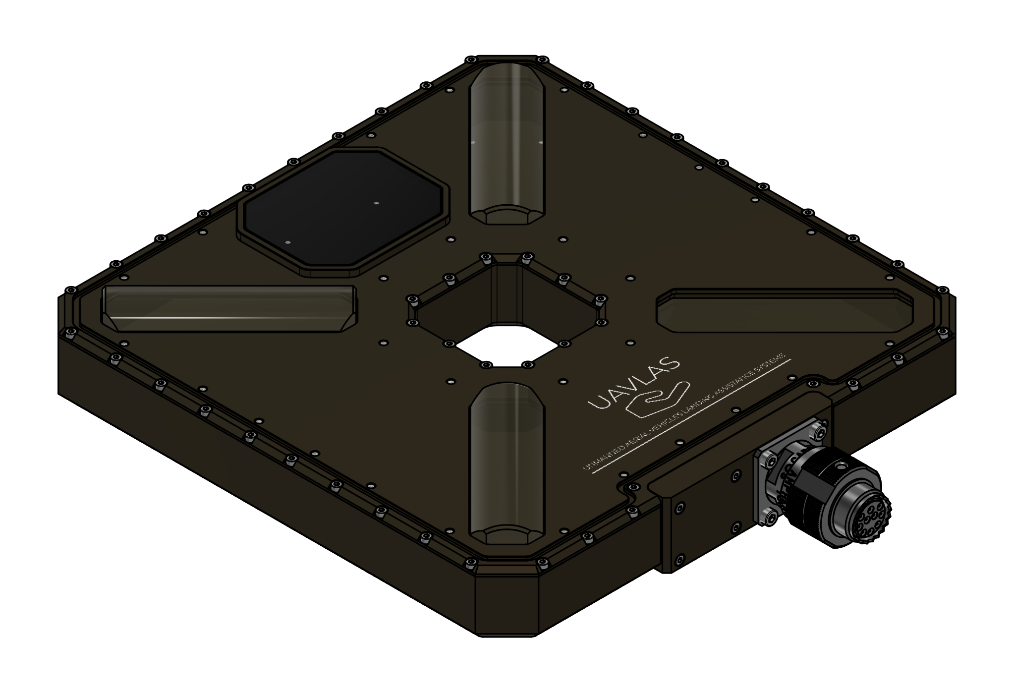
Figure: ULSDV-XS-G3-TX Transmitter
Receiver (Onboard Unit)
The ULS-XSpot-G3 uses the shared ULSDV-HLXS-G3-RXM receiver unit, identical to the one used in ULS-Heli-G3.
- Device code: ULSDV-HLXS-G3-RXM
- Primary function: Optical IR field sensor for precision positioning
- Optical central wavelength: 940nm
System architecture uses 2 identical RXM receiver units operating with the same priority.
Both RXM units are used for redundancy and for yaw orientation estimation using a triangular method in MRX mode.
Figure: ULSDV-HLXS-G3-RXM Receiver
RS422–UART Onboard Adapter
When the autopilot has only a UART interface, the ULSDV-HLXS-G3 RS422-to-UART adapter (ULS-XX-UART-RS422) is used onboard to connect the ULSDV-HLXS-G3-RXM receiver to the autopilot.
Figure: ULS-XX-UART-RS422 Onboard Adapter
USB–RS422 Ground Adapter
The ULS-XX-USB-RS422 adapter is used on the ground to connect the ULSDV-XS-G3-TX transmitter to a PC for configuration and control.
Figure: ULS-XX-USB-RS422 Ground Adapter
System Wiring Schematics
Figure: HL/XS G3 Ground-Side Wiring Schematic
Figure: HL/XS G3 Onboard Wiring Schematic
Part Numbering
| Part Number | Description |
|---|---|
| ULS-XSPOT-G3 | System set with transmitter and 2 identical RXM receiver units. |
| ULSDV-XS-G3-TX | Transmitter unit (tether-compatible, centre through hole design). |
| ULSDV-HLXS-G3-RXM | RXM receiver unit (identical hardware for Set A and Set B), quantity 2 per system. |
| ULS-XX-UART-RS422 | RS422-to-UART onboard adapter for connecting RXM receiver to UART-only autopilots. |
| ULS-XX-USB-RS422 | USB-to-RS422 ground adapter for connecting transmitter to PC (configuration and control). |
| TVP00WCI-13-98P | Manufacturer Amphenol. Transmitter connector type. |
| TV06RW-13-98S | Manufacturer Amphenol. Transmitter cable connector type. |
| M83513/04-B06C | Receiver connector type. |
| M83513/03-B03C | Receiver cable connector type. |
Table: Part Numbering
System Specifications
| Parameter | Value |
|---|---|
| Distance range (m) | 30m…50m |
| Working angle (deg) | 60 |
| Data update frequency (Hz) | 20 |
| Optical emission | IR 940nm, pulsed |
| Receiver architecture | 2 identical RXM receivers with same priority |
| Redundancy mode | Dual-RXM redundancy |
| MRX yaw estimation method | Triangular method |
| Operating mode | Tethered drone, stationary or slow-moving platform |
Table: Common Specification
| Parameter | Value |
|---|---|
| Field of view (deg) | 95 |
| Dimensions (mm) | 50x54 |
| Weight (g) | 50 |
| Power consumption (W) | 10 |
| Supply voltage (V) | +12V…+24V |
| Interfaces | CAN,USB,RS422 |
Table: ULSDV-HLXS-G3-RXM Receiver Specifications Both RXM units (Set A and Set B) are the same hardware and share the specification above.
| Parameter | Value |
|---|---|
| Field of emitting (deg) | 30 (60 in Wide Field) |
| Centre through hole (mm) | 47 x 47 |
| Dimensions (mm) | 254 x 214 |
| Weight (g) | 1960 |
| Power consumption (W) | 20W |
| Supply voltage (V) | +18V..+24V |
| Interfaces | CAN, RS422 |
Table: ULSDV-XS-G3-TX Transmitter (Ground) Specifications
Interface Summary
The ULS-XSpot-G3 system uses optical, RS422, CAN, USB, and adapter-assisted UART connectivity depending on subsystem role and host platform capability.
- Transmitter to receiver: optical IR link, 940nm pulsed
- Transmitter to control PC: USB to RS422 adapter path
- Receiver to host system: native RS422, CAN, USB, or adapter-assisted UART
For connector, pinout, signal, and protocol definitions, refer to ULSDC-PBICD190426-ULS-XSpot-G3-ICD.
Mechanical Dimensions
| Component | Dimensions (mm) | Notes |
|---|---|---|
| ULSDV-HLXS-G3-RXM | ~ 50mm x 52mm | Without connector |
| ULSDV-XS-G3-TX | ~254mm x 214mm | Without connector. Centre through hole 47mm x 47mm for tether cable |
Table: Mechanical Dimensions
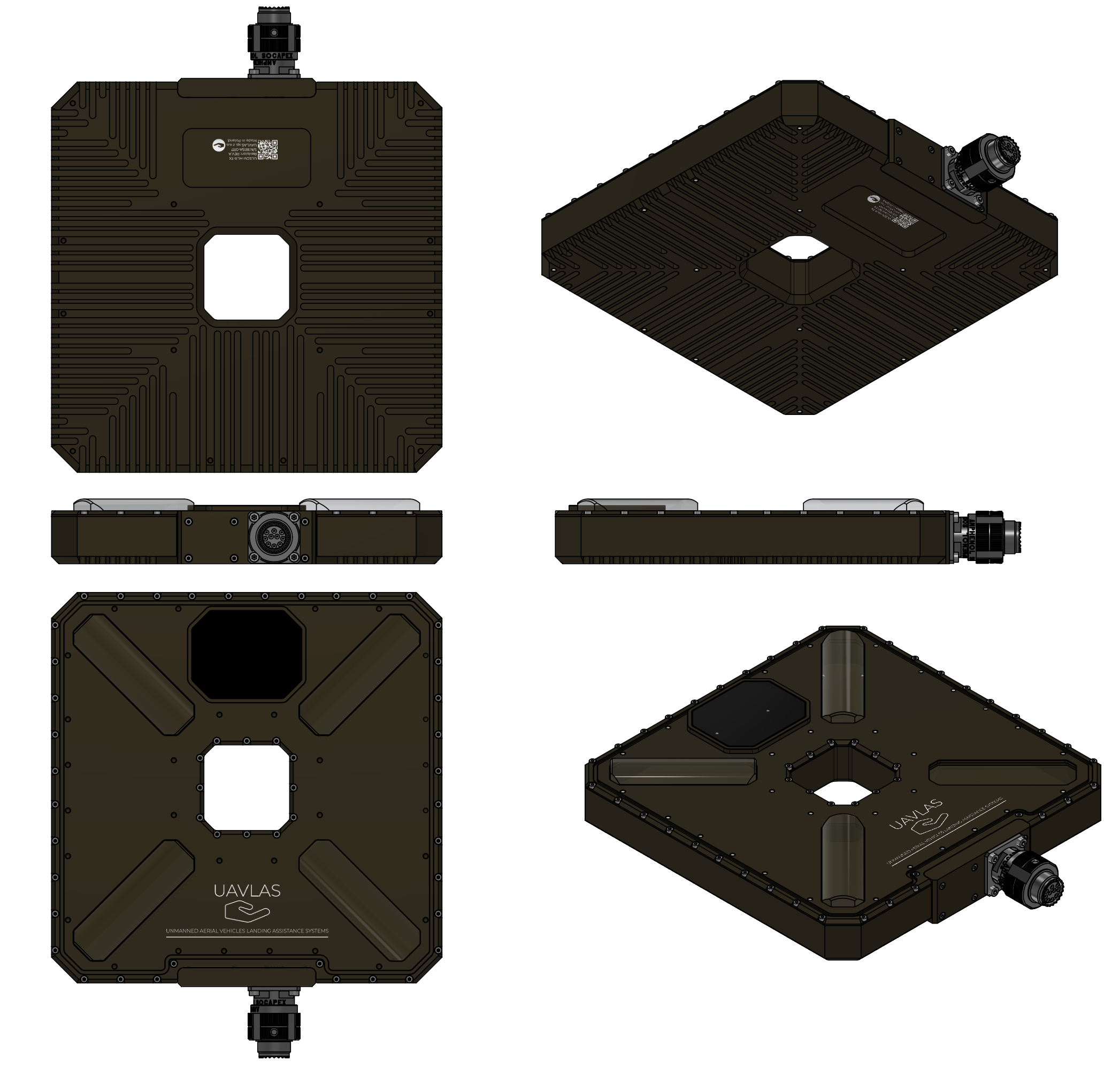
Figure: ULSDV-XS-G3-TX Projection Views (Color)
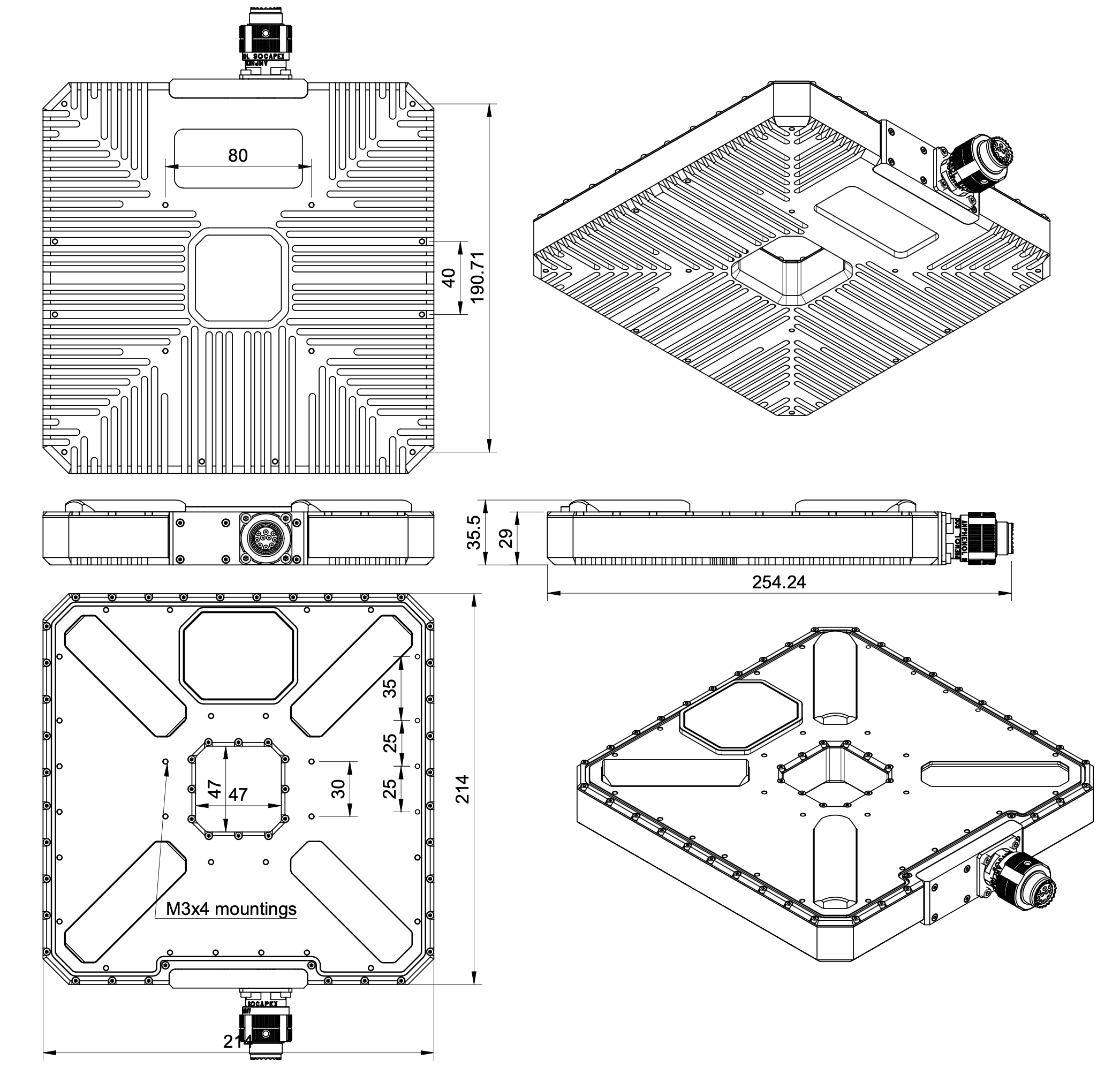
Figure: ULSDV-XS-G3-TX Transmitter Dimensions
Figure: ULSDV-HLXS-G3-RXM Projection Views (Color)
Figure: ULSDV-HLXS-G3-RXM Receiver Dimensions
Packaging Information
| Item | Packaging Value |
|---|---|
| Packaging type | Rugged case |
| Unit net weight | 2500 |
| Unit gross weight | 4500 |
| Box dimensions | 180x380x400 |
Table: Packaging Information
Environmental Conditions
Equipment is designed to meet stringent military and maritime operational requirements, providing reliable performance in the most demanding environmental conditions including shipboard operations, offshore platforms, and tactical deployments.
Operating Temperature Range
- Extended operating range: -40°C to +85°C
- Meets MIL-STD-810 requirements for temperature extremes
- Arctic to desert operations capability
- No performance degradation across full temperature range
- Qualified for rapid temperature transitions and thermal shock
- Cold-soak start capability from -40°C
Humidity and Salt Fog Resistance
- Relative humidity: Up to 95% (condensing)
- Salt fog resistant per MIL-STD-810 Method 509
- Maritime environment qualified for shipboard operations
- Corrosion-resistant materials and protective coatings
- Protected against salt spray and marine atmosphere
- Suitable for offshore platform installations
Ingress Protection
- IP67 rated (Dust tight and water immersion resistant)
- 6 - Complete protection against dust, sand, and particulate ingress
- 7 - Protected against temporary immersion in water (up to 1 meter depth for 30 minutes)
- Exceeds requirements for shipboard and maritime operations
- Protected against:
- Heavy rain and sea spray
- Temporary submersion (deck washing, wave impact)
- Sand and dust storms
- Contaminated environments
Shock and Vibration
- Vibration: MIL-STD-810 Method 514
- Helicopter vibration profile qualified
- Shipboard vibration and shock resistant
- Continuous operation during vibration
- Mechanical Shock: MIL-STD-810 Method 516
- Drop and impact qualified
- Transportation and handling shock resistant
- Crash survival design considerations
Electromagnetic Compatibility
- EMI/EMC: MIL-STD-461 compliant
- Electromagnetic interference immunity
- Low electromagnetic emissions
- RF coexistence with military avionics
- Lightning protection per MIL-STD-464
- ESD Protection: IEC 61000-4-2
- Contact discharge: ±8kV
- Air discharge: ±15kV
Storage Conditions
- Storage temperature: -55°C to +85°C
- Relative humidity: Up to 95% (condensing)
- Long-term storage in uncontrolled environments
- Sealed for preservation and long-term depot storage
Altitude and Pressure
- Operating altitude: -500m to +4500m above sea level
- Storage altitude: -500m to +12000m
- Pressure differential resistant
- Suitable for high-altitude helicopter operations
Maintenance and Serviceability
- Designed for field maintenance and repair
- Minimal preventive maintenance required
- Accessible components for service and inspection
- Environmental seals serviceable in the field
- Long service intervals suitable for deployed operations
Note: All environmental specifications are subject to final qualification testing. Contact UAVLAS for the most current test data and certification documentation. Custom environmental testing and certification to specific standards available upon request.
Optical Radiation Safety (IR Emission)
The transmitter (ground unit) emits pulsed infrared optical radiation with a centre wavelength of 940nm. The receivers are optical sensors only and do not emit optical radiation.
INFRARED RADIATION IS EMITTED FROM THE TRANSMITTER OPTICAL APERTURES WHENEVER THE UNIT IS POWERED. Do not look into the transmitter emitter apertures at close range. IR emission at 940nm is invisible and does not trigger the blink or aversion reflex, so the eye receives no natural warning of exposure.
Why This Warning Is Given
Radiation at 940nm is outside the visible range. The protective mechanisms that limit exposure to bright visible sources — the blink reflex, pupil constriction, and the instinct to look away — are not triggered by an invisible source. Exposure time is therefore limited only by operator behaviour, which is why the precautions below are given as operating instructions and not left to the operator’s judgement.
The transmitter is a positioning beacon. It is not an illumination product and is not intended to be viewed at any time.
Operating Precautions
- Do not look directly into the transmitter emitter apertures from a distance of less than 1 metre while the unit is powered.
- Treat the transmitter as emitting whenever supply voltage is applied, including when no receiver is present and no positioning data is being transferred.
- Switch emission off before working directly in front of the transmitter. Use the Illumination parameter in ULS-Tools to disable emission, or disconnect supply power.
- Do not view the powered transmitter through binoculars, telescopes, camera lenses, magnifiers, or any other light-collecting instrument. Such optics concentrate the emission and can raise the exposure at the eye by orders of magnitude compared with unaided viewing.
- Do not add, remove, or modify optical elements of the transmitter. Added optics change the emission characteristics and invalidate any photobiological classification of the unit.
- Position the transmitter so that the emission field is directed away from work positions and walkways where personnel stay for extended periods.
- Servicing personnel working inside the emission field at close range should disable emission first rather than rely on viewing distance.
Classification and Applicable Standards
| Item | Value |
|---|---|
| Emitter type | Incoherent IR LED array (not a laser) |
| Centre wavelength | 940nm |
| Emission mode | Pulsed |
| Applicable standard | IEC 62471 / EN 62471, Photobiological safety of lamps and lamp systems |
| Classification distance | 200mm (non-GLS source, per IEC 62471) |
| Risk group | TBD — to be entered from the IEC 62471 assessment report |
| Hazard distance | TBD — to be entered from the IEC 62471 assessment report |
Table: Optical Radiation Safety Data
The transmitter uses light emitting diodes, not laser emitters. LED sources are assessed under IEC 62471; the laser product standard IEC 60825-1 does not apply to this product.
For a 940nm source the applicable exposure limits are the retinal thermal hazard (380nm to 1400nm), the retinal thermal hazard for a weak visual stimulus (780nm to 1400nm, which applies specifically to sources that give no visual cue), and the infrared hazard to the cornea and lens (780nm to 3000nm). The corneal and lens limits are intended for chronic exposures longer than 1000s at a daily averaged irradiance of 100 W/m² or more.
Organisations operating this equipment within the European Union are additionally subject to Directive 2006/25/EC on the exposure of workers to artificial optical radiation, which requires the employer to assess worker exposure against the exposure limit values given in Annex I of that directive. UAVLAS provides the emission data needed for that assessment on request.
Compliance and Standards
- Document classification and release control as defined in metadata
- Product-specific compliance statements to be finalized for release
Ordering Information
Use the part numbering section to identify system variants, subassemblies, and related accessories.
Change Control
All changes to this document must be reviewed and approved by the relevant technical leads and stakeholders
References
- ULSDC-PBICD190426-ULS-XSpot-G3-ICD
- ULSDC-PBOM190426-ULS-XSpot-G3-Operation-Manual
12.2 - ULS-XSpot-G3 Interface Control Document
Interface Control Document ULSDC-PBICD190426, version 0.1.6
ULSDC-PBICD190426 · version 0.1.6 · issued August 9, 2026
The numbered PDF is the controlled copy: download it from the portal.
Introduction
Purpose
This document defines the interfaces between ULS-XSpot-G3 components, including one tether-compatible transmitter (ULSDV-XS-G3-TX) and 2 identical, equal-priority RXM receivers (ULSDV-HLXS-G3-RXM). The dual RXM architecture is used for redundancy and for yaw orientation estimation using a triangular method in MRX mode.
ULS-XSpot-G3 shares the HL/XS G3 platform with ULS-Heli-G3. Optical, electrical, and communication interfaces are identical to ULS-Heli-G3; the only difference is the transmitter case, which has a centre through hole for tether cable passage.
Scope
This document is intended for system engineers, integrators, and developers working with ULS-XSpot-G3 systems in tethered drone applications.
Assumptions and Exclusions
- This document defines interfaces only; product selection and overview information belong in the datasheet.
- Installation, calibration, and operating procedures belong in the operation manual.
System Components
Transmitter (Ground Unit)
The ULS-XSpot-G3 transmitter (ULSDV-XS-G3-TX) is the ground-side unit that emits the optical IR positioning field. It uses the same optical, electrical, and communication design as the ULS-Heli-G3 transmitter (ULSDV-HL-G3-TX); the only difference is a through hole in the centre of the case that allows the tether cable to pass through the unit.
- Device code: ULSDV-XS-G3-TX
- Primary function: Optical IR field emission for precision positioning
- Optical emission parameters: 940nm, pulsed
- Tether-compatible design: centre through hole (47 x 47 mm) for tether cable passage
Figure: ULSDV-XS-G3-TX Transmitter
Receiver (Onboard Unit)
The ULS-XSpot-G3 uses the shared ULSDV-HLXS-G3-RXM receiver unit, identical to the one used in ULS-Heli-G3.
- Device code: ULSDV-HLXS-G3-RXM
- Primary function: Optical IR field sensor for precision positioning
- Optical central wavelength: 940nm
System architecture uses 2 identical RXM receiver units operating with the same priority.
Both RXM units are used for redundancy and for yaw orientation estimation using a triangular method in MRX mode.
Figure: ULSDV-HLXS-G3-RXM Receiver
RS422–UART Onboard Adapter
When the autopilot has only a UART interface, the ULSDV-HLXS-G3 RS422-to-UART adapter (ULS-XX-UART-RS422) is used onboard to connect the ULSDV-HLXS-G3-RXM receiver to the autopilot.
Figure: ULS-XX-UART-RS422 Onboard Adapter
USB–RS422 Ground Adapter
The ULS-XX-USB-RS422 adapter is used on the ground to connect the ULSDV-XS-G3-TX transmitter to a PC for configuration and control.
Figure: ULS-XX-USB-RS422 Ground Adapter
Interface Overview
Figure: ULS-XSpot-G3 System Interfaces Overview
Interface Summary
- Transmitter to control PC
- Transmitter to receiver optical link
- Receiver to autopilot, PC, and network interfaces
- Power distribution and interface-related electrical constraints
Physical Interfaces
Figure: ULS-XSpot-G3 Physical Interfaces Overview
Transmitter to Control PC Interface
The transmitter (ULSDV-XS-G3-TX) connects to a PC via the ULS-XX-USB-RS422 ground adapter for configuration and control.
Figure: ULS-XX-USB-RS422 Adapter Pinout
| Pin | Function |
|---|---|
| 1 | +V supply +18V…+27V to Transmitter |
| 2 | GND |
| 3 | RS422 A RX+ (Adapter Input) |
| 4 | RS422 B RX- (Adapter Input) |
| 5 | RS422 Y TX- (Adapter Output) |
| 6 | RS422 Z TX+ (Adapter Output) |
| 7,8 | +V supply +18V…+27V Power input from battery |
*Table: ULS-XX-USB-RS422 Pinout *
Data Types
- Status information
- Control signals
- Transmitter configuration
- External IMU/COMPASS data
Connection Types
- CAN Bus – For network communication
- USB – Via ULS-XX-USB-RS422 adapter (PC side)
- RS422 – Native transmitter interface; for serial communication with external sensors
Transmitter Pinout
ULSDV-XS-G3-TX Transmitter pinout information.
Figure: Transmitter connector
| Pin | Function |
|---|---|
| A | +V supply +18V…+27V |
| B | RS422 RX+ (A) |
| C | RS422 RX- (B) |
| D | RS422 TX+ (Y) |
| E | RS422 TX- (Z) |
| F | GND |
| G | C1L |
| H | C1H |
| J | GND |
| K | GND |
Table: Transmitter Connector Pinout (ULSDV-XS-G3-TX)
Do not connect or disconnect the transmitter interface under power unless approved by final hardware instructions.
The transmitter connects to a PC via the ULS-XX-USB-RS422 ground adapter (USB side to PC, RS422 side to transmitter connector).
Transmitter to Receiver Interface
The transmitter and receiver use an optical interface to exchange data. Transmission uses pulsed IR emission at 940 nanometers. Data transmission is only in the direction from the transmitter to the receiver.
Data Types
- Position encoded
- Status encoded data (transmitter orientation and instructions)
Connection Type
- Optical IR 940nm (pulsed) – Infrared optical link
The transmitter emits invisible infrared radiation whenever it is powered. Observe the precautions in the Optical Radiation Safety section before working in front of the transmitter.
Receiver Interfaces (RXM Set A and RXM Set B)
Both RXM receivers (ULSDV-HLXS-G3-RXM) are identical and have the same priority in system operation.
When the autopilot provides only a UART interface, connect the RXM receiver RS422 output through the ULS-XX-UART-RS422 onboard adapter.
Figure: ULS-XX-UART-RS422 Adapter Pinout
| Pin | Function |
|---|---|
| 1 | +5V |
| 2 | UART-TX (Adapter Out) |
| 3 | UART-RX (Adapter In) |
| 4 | GND |
Table: ULSDV-XX-UART-RS422-R0 4 pin connector pinout
| Pin | Function |
|---|---|
| 1 | GND |
| 3 | RS422 A RX+ (Adapter Input) |
| 4 | RS422 B RX- (Adapter Input) |
| 5 | RS422 Y TX- (Adapter Output) |
| 6 | RS422 Z TX+ (Adapter Output) |
| 2 | GND |
Table: ULSDV-XX-UART-RS422-R0 6 pin connector pinout
Data Types
- MAVLink messages
- ULS-Blitz frames
- ASCII protocol
- MRX-mode yaw estimation data (triangular method)
Connection Types
- RS422 – Native receiver interface
- UART – Via ULS-XX-UART-RS422 adapter (for UART-only autopilots)
- CAN – Network communication
- USB – Direct PC connection
Receiver Pinout
ULSDV-HLXS-G3-RXM Receiver pinout information.
Both receivers (Set A and Set B) are identical, equal-priority units. The pinout is the same for both.
Figure: Receiver connector
| Pin | Function |
|---|---|
| 1 | + V supply +12V..+25V |
| 2 | C2H |
| 3 | C2L |
| 4 | GND - Ground connection |
| 5 | + V supply +12V..+25V |
| 6 | C1H |
| 7 | C1L |
| 8 | GND - Ground connection |
| 9 | + V supply +12V..+25V |
| 10 | RS422 Z |
| 11 | RS422 Y |
| 12 | RS422 A |
| 13 | RS422 B |
| 14 | GND - Ground connection |
| 15 | GND - Ground connection |
Table: ULSDV-HLXS-G3-RXM Connector Pinout When the autopilot provides only a UART interface, connect the receiver RS422 output to the autopilot via the ULS-XX-UART-RS422 onboard adapter.
For receiver setup unscrew protection part to get access to usb connector.
Figure: Receiver USB connector
Due hardware limitation of current revision USB connector with thin shield required
Receiver case not sealed when USB cover removed.
Electrical Interfaces
Figure: Power Distribution and Connections
Transmitter Electrical Characteristics
| Parameter | Value | Unit | Notes |
|---|---|---|---|
| Supply Voltage | +18…+26 | V | |
| Supply Current | 2.5 | A | |
| Power Consumption | 25 | W |
Table: Transmitter Electrical Specifications Tethered System Power: Transmitter may be continuously powered from a ground station power supply via the tether cable.
Receiver Electrical Characteristics (Per RXM Set)
| Parameter | Value | Unit | Notes |
|---|---|---|---|
| Supply Voltage | +12…+26 | V | |
| Supply Current | 1 | A | |
| Power Consumption | 10 | W |
Table: Receiver Electrical Specifications
Communication Interfaces
Supported Communication Methods
- Optical IR 940nm pulsed link between transmitter and receiver
- RS422 for native wired subsystem interfaces
- UART via ULS-XX-UART-RS422 where required by the host autopilot
- CAN for network communication
- USB for direct PC access where supported
Data Definitions
Data Categories
- Position-encoded optical data
- Transmitter status and orientation data
- MAVLink messages
- ULS-Blitz frames
- ASCII protocol data
- MRX yaw estimation data
Message payload definitions are given in ULSDC-PBDS051125-ULS-DeCoNet Blitz Messages Specification.
Functional Interfaces
Figure: Data Flow and Functional Interfaces
Data Exchange
The ULS-XSpot-G3 system data exchange mechanism, applied to tethered drone operations:
Control PC Functions:
- Configure and view status of transmitter
- Set configuration of receivers
- Send control signals (On/off, compass override information)
- Monitor tethered operation parameters
External Equipment:
- External IMU/Compass equipment can be used to override internal IMU/compass information
- Tether management system integration for position reference
Receiver Functions:
- Accept data from transmitter over IR signal (position field information and ground unit IMU data)
- Accept NED and Attitude information from autopilot to convert coordinate system
- Multiple receivers (MRX mode) communicate to calculate vehicle orientation (YAW) using triangular method
- Send position offset data to autopilot
- Support for tethered flight modes and station-keeping
Mechanical Interfaces
| Component | Dimensions (mm) | Notes |
|---|---|---|
| ULSDV-HLXS-G3-RXM | ~ 50mm x 52mm | Without connector |
| ULSDV-XS-G3-TX | ~254mm x 214mm | Without connector. Centre through hole 47mm x 47mm for tether cable |
Table: Mechanical Dimensions
Figure: ULSDV-XS-G3-TX Projection Views (Color)
Figure: ULSDV-XS-G3-TX Transmitter Dimensions
Figure: ULSDV-HLXS-G3-RXM Projection Views (Color)
Figure: ULSDV-HLXS-G3-RXM Receiver Dimensions
The transmitter centre through hole (47mm x 47mm) is reserved for tether cable passage. Do not route the tether cable across the optical emission apertures.
Environmental Conditions
Equipment is designed to meet stringent military and maritime operational requirements, providing reliable performance in the most demanding environmental conditions including shipboard operations, offshore platforms, and tactical deployments.
Operating Temperature Range
- Extended operating range: -40°C to +85°C
- Meets MIL-STD-810 requirements for temperature extremes
- Arctic to desert operations capability
- No performance degradation across full temperature range
- Qualified for rapid temperature transitions and thermal shock
- Cold-soak start capability from -40°C
Humidity and Salt Fog Resistance
- Relative humidity: Up to 95% (condensing)
- Salt fog resistant per MIL-STD-810 Method 509
- Maritime environment qualified for shipboard operations
- Corrosion-resistant materials and protective coatings
- Protected against salt spray and marine atmosphere
- Suitable for offshore platform installations
Ingress Protection
- IP67 rated (Dust tight and water immersion resistant)
- 6 - Complete protection against dust, sand, and particulate ingress
- 7 - Protected against temporary immersion in water (up to 1 meter depth for 30 minutes)
- Exceeds requirements for shipboard and maritime operations
- Protected against:
- Heavy rain and sea spray
- Temporary submersion (deck washing, wave impact)
- Sand and dust storms
- Contaminated environments
Shock and Vibration
- Vibration: MIL-STD-810 Method 514
- Helicopter vibration profile qualified
- Shipboard vibration and shock resistant
- Continuous operation during vibration
- Mechanical Shock: MIL-STD-810 Method 516
- Drop and impact qualified
- Transportation and handling shock resistant
- Crash survival design considerations
Electromagnetic Compatibility
- EMI/EMC: MIL-STD-461 compliant
- Electromagnetic interference immunity
- Low electromagnetic emissions
- RF coexistence with military avionics
- Lightning protection per MIL-STD-464
- ESD Protection: IEC 61000-4-2
- Contact discharge: ±8kV
- Air discharge: ±15kV
Storage Conditions
- Storage temperature: -55°C to +85°C
- Relative humidity: Up to 95% (condensing)
- Long-term storage in uncontrolled environments
- Sealed for preservation and long-term depot storage
Altitude and Pressure
- Operating altitude: -500m to +4500m above sea level
- Storage altitude: -500m to +12000m
- Pressure differential resistant
- Suitable for high-altitude helicopter operations
Maintenance and Serviceability
- Designed for field maintenance and repair
- Minimal preventive maintenance required
- Accessible components for service and inspection
- Environmental seals serviceable in the field
- Long service intervals suitable for deployed operations
Note: All environmental specifications are subject to final qualification testing. Contact UAVLAS for the most current test data and certification documentation. Custom environmental testing and certification to specific standards available upon request.
Optical Radiation Safety (IR Emission)
The transmitter (ground unit) emits pulsed infrared optical radiation with a centre wavelength of 940nm. The receivers are optical sensors only and do not emit optical radiation.
INFRARED RADIATION IS EMITTED FROM THE TRANSMITTER OPTICAL APERTURES WHENEVER THE UNIT IS POWERED. Do not look into the transmitter emitter apertures at close range. IR emission at 940nm is invisible and does not trigger the blink or aversion reflex, so the eye receives no natural warning of exposure.
Why This Warning Is Given
Radiation at 940nm is outside the visible range. The protective mechanisms that limit exposure to bright visible sources — the blink reflex, pupil constriction, and the instinct to look away — are not triggered by an invisible source. Exposure time is therefore limited only by operator behaviour, which is why the precautions below are given as operating instructions and not left to the operator’s judgement.
The transmitter is a positioning beacon. It is not an illumination product and is not intended to be viewed at any time.
Operating Precautions
- Do not look directly into the transmitter emitter apertures from a distance of less than 1 metre while the unit is powered.
- Treat the transmitter as emitting whenever supply voltage is applied, including when no receiver is present and no positioning data is being transferred.
- Switch emission off before working directly in front of the transmitter. Use the Illumination parameter in ULS-Tools to disable emission, or disconnect supply power.
- Do not view the powered transmitter through binoculars, telescopes, camera lenses, magnifiers, or any other light-collecting instrument. Such optics concentrate the emission and can raise the exposure at the eye by orders of magnitude compared with unaided viewing.
- Do not add, remove, or modify optical elements of the transmitter. Added optics change the emission characteristics and invalidate any photobiological classification of the unit.
- Position the transmitter so that the emission field is directed away from work positions and walkways where personnel stay for extended periods.
- Servicing personnel working inside the emission field at close range should disable emission first rather than rely on viewing distance.
Classification and Applicable Standards
| Item | Value |
|---|---|
| Emitter type | Incoherent IR LED array (not a laser) |
| Centre wavelength | 940nm |
| Emission mode | Pulsed |
| Applicable standard | IEC 62471 / EN 62471, Photobiological safety of lamps and lamp systems |
| Classification distance | 200mm (non-GLS source, per IEC 62471) |
| Risk group | TBD — to be entered from the IEC 62471 assessment report |
| Hazard distance | TBD — to be entered from the IEC 62471 assessment report |
Table: Optical Radiation Safety Data
The transmitter uses light emitting diodes, not laser emitters. LED sources are assessed under IEC 62471; the laser product standard IEC 60825-1 does not apply to this product.
For a 940nm source the applicable exposure limits are the retinal thermal hazard (380nm to 1400nm), the retinal thermal hazard for a weak visual stimulus (780nm to 1400nm, which applies specifically to sources that give no visual cue), and the infrared hazard to the cornea and lens (780nm to 3000nm). The corneal and lens limits are intended for chronic exposures longer than 1000s at a daily averaged irradiance of 100 W/m² or more.
Organisations operating this equipment within the European Union are additionally subject to Directive 2006/25/EC on the exposure of workers to artificial optical radiation, which requires the employer to assess worker exposure against the exposure limit values given in Annex I of that directive. UAVLAS provides the emission data needed for that assessment on request.
Integration Wiring Diagrams
Figure: HL/XS G3 Ground-Side Wiring Schematic
Figure: HL/XS G3 Onboard Wiring Schematic
Part Numbering
| Part Number | Description |
|---|---|
| ULS-XSPOT-G3 | System set with transmitter and 2 identical RXM receiver units. |
| ULSDV-XS-G3-TX | Transmitter unit (tether-compatible, centre through hole design). |
| ULSDV-HLXS-G3-RXM | RXM receiver unit (identical hardware for Set A and Set B), quantity 2 per system. |
| ULS-XX-UART-RS422 | RS422-to-UART onboard adapter for connecting RXM receiver to UART-only autopilots. |
| ULS-XX-USB-RS422 | USB-to-RS422 ground adapter for connecting transmitter to PC (configuration and control). |
| TVP00WCI-13-98P | Manufacturer Amphenol. Transmitter connector type. |
| TV06RW-13-98S | Manufacturer Amphenol. Transmitter cable connector type. |
| M83513/04-B06C | Receiver connector type. |
| M83513/03-B03C | Receiver cable connector type. |
Table: Part Numbering
Applicable Documents
- ULSDC-PBDS190426-ULS-XSpot-G3-Datasheet
- ULSDC-PBOM190426-ULS-XSpot-G3-Operation-Manual
- ULSDC-PBDS051125-ULS-DeCoNet Blitz Messages Specification
Change Control
All changes to this document must be reviewed and approved by the relevant technical leads and stakeholders
12.3 - ULS-XSpot-G3 Operation Manual
Operation Manual ULSDC-PBOM190426, version 0.1.5
ULSDC-PBOM190426 · version 0.1.5 · issued August 9, 2026
The numbered PDF is the controlled copy: download it from the portal.
Introduction
Purpose
This manual provides installation, configuration, operation, verification, and troubleshooting guidance for the ULS-XSpot-G3 system.
Scope
This manual covers one tether-compatible transmitter and 2 identical, equal-priority RXM receivers used in the ULS-XSpot-G3 architecture.
Intended Audience
This manual is intended for operators, installers, technicians, and integrators responsible for commissioning and using the system.
Safety Information
- WARNING: The transmitter emits invisible infrared radiation when powered. Do not look into the emitter apertures at close range. See the Optical Radiation Safety section below.
- CAUTION: Route the tether cable through the transmitter centre through hole. Do not route the cable across the optical emission apertures.
- CAUTION: Do not connect or disconnect the transmitter interface under power.
Optical Radiation Safety (IR Emission)
The transmitter (ground unit) emits pulsed infrared optical radiation with a centre wavelength of 940nm. The receivers are optical sensors only and do not emit optical radiation.
INFRARED RADIATION IS EMITTED FROM THE TRANSMITTER OPTICAL APERTURES WHENEVER THE UNIT IS POWERED. Do not look into the transmitter emitter apertures at close range. IR emission at 940nm is invisible and does not trigger the blink or aversion reflex, so the eye receives no natural warning of exposure.
Why This Warning Is Given
Radiation at 940nm is outside the visible range. The protective mechanisms that limit exposure to bright visible sources — the blink reflex, pupil constriction, and the instinct to look away — are not triggered by an invisible source. Exposure time is therefore limited only by operator behaviour, which is why the precautions below are given as operating instructions and not left to the operator’s judgement.
The transmitter is a positioning beacon. It is not an illumination product and is not intended to be viewed at any time.
Operating Precautions
- Do not look directly into the transmitter emitter apertures from a distance of less than 1 metre while the unit is powered.
- Treat the transmitter as emitting whenever supply voltage is applied, including when no receiver is present and no positioning data is being transferred.
- Switch emission off before working directly in front of the transmitter. Use the Illumination parameter in ULS-Tools to disable emission, or disconnect supply power.
- Do not view the powered transmitter through binoculars, telescopes, camera lenses, magnifiers, or any other light-collecting instrument. Such optics concentrate the emission and can raise the exposure at the eye by orders of magnitude compared with unaided viewing.
- Do not add, remove, or modify optical elements of the transmitter. Added optics change the emission characteristics and invalidate any photobiological classification of the unit.
- Position the transmitter so that the emission field is directed away from work positions and walkways where personnel stay for extended periods.
- Servicing personnel working inside the emission field at close range should disable emission first rather than rely on viewing distance.
Classification and Applicable Standards
| Item | Value |
|---|---|
| Emitter type | Incoherent IR LED array (not a laser) |
| Centre wavelength | 940nm |
| Emission mode | Pulsed |
| Applicable standard | IEC 62471 / EN 62471, Photobiological safety of lamps and lamp systems |
| Classification distance | 200mm (non-GLS source, per IEC 62471) |
| Risk group | TBD — to be entered from the IEC 62471 assessment report |
| Hazard distance | TBD — to be entered from the IEC 62471 assessment report |
Table: Optical Radiation Safety Data
The transmitter uses light emitting diodes, not laser emitters. LED sources are assessed under IEC 62471; the laser product standard IEC 60825-1 does not apply to this product.
For a 940nm source the applicable exposure limits are the retinal thermal hazard (380nm to 1400nm), the retinal thermal hazard for a weak visual stimulus (780nm to 1400nm, which applies specifically to sources that give no visual cue), and the infrared hazard to the cornea and lens (780nm to 3000nm). The corneal and lens limits are intended for chronic exposures longer than 1000s at a daily averaged irradiance of 100 W/m² or more.
Organisations operating this equipment within the European Union are additionally subject to Directive 2006/25/EC on the exposure of workers to artificial optical radiation, which requires the employer to assess worker exposure against the exposure limit values given in Annex I of that directive. UAVLAS provides the emission data needed for that assessment on request.
System Overview
ULS-XSpot-G3 is a tethered drone precision optical positioning system built around a tether-compatible ground transmitter (ULSDV-XS-G3-TX) and 2 equal-priority RXM onboard receivers (ULSDV-HLXS-G3-RXM). The system supports redundant onboard sensing and MRX-based yaw estimation for tethered flight and landing support.
ULS-XSpot-G3 uses the same HL/XS G3 platform as ULS-Heli-G3. Installation, configuration, and operating procedures are identical, except for the tether routing through the transmitter centre through hole (47mm x 47mm).
Package Contents
- 1x ULSDV-XS-G3-TX ground transmitter unit
- 2x ULSDV-HLXS-G3-RXM receiver units (Set A and Set B)
- 1x ULS-XX-USB-RS422 adapter (ground configuration)
- 2x ULS-XX-UART-RS422 onboard adapters (receiver-to-autopilot UART interface)
- Cables and mounting hardware
- Documentation package (may supply in online form)
System Requirements
- Transmitter power: +18V…+26V, 2.5A
- RXM receiver power (each): +12V…+26V, 1A
- Supported autopilots: Ardupilot and PX4 based systems (MAVLink V2), or any host supporting RS422/CAN/UART ULS protocols
Installation
Wiring Schematics
Figure: HL/XS G3 Ground-Side Wiring Schematic
Figure: HL/XS G3 Onboard Wiring Schematic
Transmitter Installation
The ULSDV-XS-G3-TX transmitter is a tether-compatible ground unit with a centre through hole for tether cable passage.
Figure: ULSDV-XS-G3-TX Transmitter
Figure: ULSDV-XS-G3-TX Dimensions
- Mounting instructions: device can be mounted from top side or from bottom side. Use corresponding M3 screws to mount device on place. 3D model and pad example can be provided by UAVLAS under request.
- Orientation requirements: The device must be positioned with the optical elements facing upward. Make sure that no foreign objects obstruct the optical elements within the transmitter’s entire field of view.
- Tether routing: route the tether cable through the centre through hole (47mm x 47mm) before mounting. The tether must not cross the optical emission apertures.
Receiver Installation
Both receivers are identical and operate with equal priority.
Figure: ULSDV-HLXS-G3-RXM Receiver
Figure: ULSDV-HLXS-G3-RXM Dimensions
- Receivers location and orientation: The device must be positioned with the optical elements facing downward. Ensure that the optical elements are not obstructed by foreign objects within the transmitter’s entire field of view.
- Install the receivers at least 0.5 meters apart; this will ensure reliable operation in MRX mode even if one of the receivers moves out of the system’s field of view. Typically, the first receiver (the one connected to the main autopilot) is located near the center of the landing point, and the second receiver is located at the tail. The maximum installation distance is 3 meters.
Configuration
Connecting Transmitter to PC
Use the ULS-XX-USB-RS422 adapter to connect the transmitter RS422 interface to a PC USB port for configuration and control via ULS-Tools software.
Figure: ULS-XX-USB-RS422 Ground Adapter
Figure: ULS-XX-USB-RS422 Adapter Pinout
Connecting Receiver to UART Autopilot
When the autopilot provides only a UART interface, use the ULS-XX-UART-RS422 onboard adapter between the receiver RS422 output and the autopilot UART port.
Figure: ULS-XX-UART-RS422 Onboard Adapter
Figure: ULS-XX-UART-RS422 Onboard Adapter Pinout
Receiver Pinout
ULSDV-HLXS-G3-RXM Receiver pinout information.
Both receivers (Set A and Set B) are identical, equal-priority units. The pinout is the same for both.
Figure: Receiver connector
| Pin | Function |
|---|---|
| 1 | + V supply +12V..+25V |
| 2 | C2H |
| 3 | C2L |
| 4 | GND - Ground connection |
| 5 | + V supply +12V..+25V |
| 6 | C1H |
| 7 | C1L |
| 8 | GND - Ground connection |
| 9 | + V supply +12V..+25V |
| 10 | RS422 Z |
| 11 | RS422 Y |
| 12 | RS422 A |
| 13 | RS422 B |
| 14 | GND - Ground connection |
| 15 | GND - Ground connection |
Table: ULSDV-HLXS-G3-RXM Connector Pinout When the autopilot provides only a UART interface, connect the receiver RS422 output to the autopilot via the ULS-XX-UART-RS422 onboard adapter.
For receiver setup unscrew protection part to get access to usb connector.
Figure: Receiver USB connector
Due hardware limitation of current revision USB connector with thin shield required
Receiver case not sealed when USB cover removed.
Transmitter Pinout
ULSDV-XS-G3-TX Transmitter pinout information.
Figure: Transmitter connector
| Pin | Function |
|---|---|
| A | +V supply +18V…+27V |
| B | RS422 RX+ (A) |
| C | RS422 RX- (B) |
| D | RS422 TX+ (Y) |
| E | RS422 TX- (Z) |
| F | GND |
| G | C1L |
| H | C1H |
| J | GND |
| K | GND |
Table: Transmitter Connector Pinout (ULSDV-XS-G3-TX)
Do not connect or disconnect the transmitter interface under power unless approved by final hardware instructions.
The transmitter connects to a PC via the ULS-XX-USB-RS422 ground adapter (USB side to PC, RS422 side to transmitter connector).
Device Configuration and Integration in ULS-Tools
ULS-XSpot-G3 is currently in pre-production stage. Use ULS-Tools Beta for configuration and firmware update:
https://github.com/UAVLAS/ULSTools-Beta/releases/
Use the adapters listed in this manual to connect each device to a PC and complete configuration in ULS-Tools before field operation.
ULS-Tools Device Dashboard
Figure: ULS-Tools Device Dashboard
Configure Transmitter
- Connect the transmitter through the ULS-XX-USB-RS422 adapter.
- Open transmitter settings and verify communication parameters.
- Set required operating parameters and click Apply Config.
Figure: ULS-Tools Transmitter Configuration
| Parameter | Description |
|---|---|
| Device Name | Name shown for the transmitter in ULS-Tools. |
| Beacon ID | Transmitter iD to be transmitter to receiver over R signal (functionality under request) |
| Device Illumination Power | IR emitter power scaling (100 for nominal operation). |
| Device Low Voltage | Voltage level where low-voltage warning is activated. |
| Device Off Voltage | Voltage level where IR emitters are disabled to prevent over-discharge. |
| Indicator Brightness | Brightness level of the transmitter status LED indicator. |
| Illumination | Enables or disables transmitter emission during configuration and operation. |
| Compass Override [deg] | Fixed heading override for installations that require manual heading alignment. |
| External Compass Only | Forces system to use only external compass data when enabled. |
| Magnetometer Offset/Scale | Calibration values for internal or external (“Ex”) magnetometer. |
| CAN Address/Speed | CAN bus node address and bitrate settings. |
| CAN Protocol | Protocol selection (ULS DECENT with ULSBlitz messages supported) Custom protocols are possible |
| CAN Termination | If system has inbuilt termination resistor this option can activate it |
Table: Transmitter Configuration Parameters
Configure Receiver (RXM)
- Connect each receiver and configure one at a time.
- Set UART protocol/baud rate to match autopilot serial configuration.
- For dual-receiver installation, verify MRX-related parameters and offsets.
- Click Apply Config after each update.
Figure: ULS-Tools Receiver Configuration
| Parameter | Description |
|---|---|
| Device Name | Name shown for the receiver in ULS-Tools. |
| Receiver Offset (Front, Right) [m] | Receiver position relative to vehicle reference point for MRX/yaw calculations. |
| Rx orientation | Receiver YAW installation orientation relative to vehicle front |
| Prediction Time [s] | Position prediction window used to smooth short signal interruptions. |
| Filter Response | Receiver position filter response tuning (higher is faster, lower is smoother). |
| Tx Level Compensation | Compensation for transmitter pan/tilt motion on moving platforms. |
| Compass Mode | Enables use of ground compass data in receiver calculations. |
| MRX Mode | Enables dual-receiver mode for yaw and redundancy features. |
| DACS Yaw Correction | Disable and enable Distance and Azimuth Correction System |
| Indicator Brightness | Brightness level of receiver status indicator. |
| Magnetometer Offset/Scale | Calibration values for internal or external (“Ex”) magnetometer. (under implementation) |
| CAN Address/Speed | CAN bus node address and bitrate settings. |
| CAN Protocol | Protocol selection (ULS DECENT with ULSBlitz messages supported) Custom protocols are possible |
| CAN Termination | If system has inbuilt termination resistor this option can activate it |
| UART Protocol | Protocol selection for autopilot communication (for example MavlinkV2). |
| UART Baud Rate | Serial baud rate; must match autopilot serial port settings. |
| UART Termination | If system has inbuilt termination resistor this option can activate it |
Table: Receiver Configuration Parameters
Compass Calibration (Ground Unit)
After installation, check compass behavior and perform calibration if required.
- Press Reset calibrations.
- Rotate the ground unit through multiple orientations to fill calibration charts.
- Press Apply calibration and Apply Config.
Figure: ULS-Tools Compass Calibration
Integration Verification in ULS-Tools
- Confirm live device telemetry is visible in charts.
- Verify stable IMU and system parameter traces before flight tests.
- Confirm receiver link and valid position updates prior to autopilot integration tests.
Figure: ULS-Tools System Parameters Chart
Figure: ULS-Tools Receiver Charts
Integration Instructions for Ardupilot Based Systems
Preparing for Integration
- Download the latest version of ULS-Tools (Beta). It is recommended to connect all devices to a PC and update firmware for all UAVLAS devices before proceeding.
- Update the autopilot to the latest Arducopter version.
- Configure the transmitter in ULS-Tools
- Configure both receivers in ULS-Tools
The system communicates with Ardupilot using the MavlinkV2 protocol (supports MAV_FRAME_BODY_FRD).
Autopilot Configuration
Setup PLND Section
| Param | Value | Comment |
|---|---|---|
| PLND_ENABLED | 1 | Enable the precision landing module |
| PLND_TYPE | 1 | Use type = 1 to enable UAVLAS sensor over the companion computer driver |
Table: Ardupilot PLND Section Parameters All other PLND parameters should remain at defaults, or be set according to your vehicle requirements.
Figure: PLND Configuration Example
It is recommended to test several Kalman filter options during test flights (or switch it off) to achieve the best performance.
Set Up Serial Communication in SERIALx Section
| Param | Value | Comment |
|---|---|---|
| SERIAL2_BAUD | 230 | Baud rate — must match the receiver UART baud rate setting |
| SERIAL2_OPTIONS | 0 | Default |
| SERIAL2_PROTOCOL | 2 | MAVlink2 protocol |
Table: Ardupilot SERIALx Section Parameters Set up serial stream rates in the SRx section. The sensor requires the following data from the autopilot:
| Param | Value | Comment |
|---|---|---|
| SR2_EXTRA1 (or MAV2_EXTRA1) | 20 | Attitude stream at 20 Hz — required for compass mode yaw orientation |
| SR2_POSITION (or MAV2_POSITION) | 20 | Optional — Vehicle LOCAL_POSITION_NED stream at 20 Hz for absolute target position calculation |
Table: Ardupilot SRx Stream Rate Parameters
Check Setup
When configuration and wiring are correct, GPS is available, and the receiver is in the field of view of the transmitter, you will see the LANDING_TARGET MAVLink message in the MAVLink Inspector (Mission Planner example shown):
Figure: LANDING_TARGET Message in MAVLink Inspector
Setup Precision Loiter Mode
Attach any unused switch to the PrecLoiter option to enable precision loiter mode:
Figure: PrecLoiter Switch Configuration
Activate the switch and confirm messages “PrecLoiter: LOW” and “PrecLoiter: HIGH” appear. After a test flight above the target, check telemetry for PL offset data.
Figure: Telemetry Data Showing PL Offsets
PID Tuning
In case of oscillations or instability during landing, check the PID parameters in Ardupilot Extended Tuning.
It is recommended to tune Position XY, Velocity XY, and Loiter Speed for the best performance:
Figure: Ardupilot Extended Tuning Parameters
Settings of Velocity XY P = 0.8, I = 0.2, D = 0.6 have worked well for some customers as a starting point.
It is recommended to start PID testing and performance validation in Precision Loiter mode before enabling full precision landing.
For additional information, see the Ardupilot documentation at https://ardupilot.org/ardupilot/
Integration Instructions for PX4 Based Systems
Preparing for Integration
- Download the latest version of ULS-Tools (Beta). It is recommended to connect all devices to a PC and update firmware for all UAVLAS devices before proceeding.
- Update the autopilot to the latest PX4 version.
- Configure the transmitter in ULS-Tools.
- Configure both receivers in ULS-Tools.
The system communicates with PX4 using the MavlinkV2 protocol (supports MAV_FRAME_LOCAL_NED).
Configure PX4 Autopilot
Values are provided as an example (Pixhawk4-mini AP):
| PX4 Parameter | Value | Comment |
|---|---|---|
| MAV_1_CONFIG | TELEM/SERIAL4 | Requires reboot to apply the next parameters |
| MAV_1_FORWARD | Enabled | Forward MAVLink messages |
| MAV_1_MODE | Onboard | Set link mode to onboard |
| SER_TEL4_BAUD | 460800_8N1 | Must match the UART baud rate set in the receiver configuration |
Table: PX4 Autopilot Configuration Parameters
Running and Testing
After configuration and wiring, power up the drone and transmitter. In QGroundControl, go to Analyze Tools → MAVLink Inspector and check for the LANDING_TARGET MAVLink message.
If the vehicle is providing a LOCAL_POSITION_NED message to the UAVLAS system and is hovering over the beacon, the field position_valid = 1 will appear in LANDING_TARGET.
To perform precision landing, create a flight plan and enable the Precision Landing option on the landing waypoint.
LANDING_TARGET may be unavailable when connected over USB. Use a telemetry channel (UART modem, etc.) to connect the drone to QGroundControl during testing.
Figure: LANDING_TARGET Message in QGroundControl
For additional information, see the PX4 documentation at https://docs.px4.io/main/en/
Operating Instructions
- Power sequence: Power device after all connectors are plugged in before powering.
- Link check procedure: Link can be checked from the configuration system during system installation, as well as during operation using a third-party device via the appropriate protocols.
- Landing and approach operation notes: The vehicle’s control system independently decides on the appropriate action based on the status of the landing system. The UAVLAS system acts as a sensor—the procedure for handling abnormal situations during operation remains the responsibility of the unmanned vehicle’s control system.
- Equal-priority RXM behavior in MRX mode: Both receivers have the same priority, and either one can be used to receive system status data.
- Tethered operation: verify that the tether cable stays inside the transmitter centre through hole over the full range of tether movement.
Service and Support
The device requires no maintenance throughout its service life.
Appendices
Technical Reference
| Parameter | Value |
|---|---|
| Distance range (m) | 30m…50m |
| Working angle (deg) | 60 |
| Data update frequency (Hz) | 20 |
| Optical emission | IR 940nm, pulsed |
| Receiver architecture | 2 identical RXM receivers with same priority |
| Redundancy mode | Dual-RXM redundancy |
| MRX yaw estimation method | Triangular method |
| Operating mode | Tethered drone, stationary or slow-moving platform |
Table: Common Specification
| Parameter | Value |
|---|---|
| Field of view (deg) | 95 |
| Dimensions (mm) | 50x54 |
| Weight (g) | 50 |
| Power consumption (W) | 10 |
| Supply voltage (V) | +12V…+24V |
| Interfaces | CAN,USB,RS422 |
Table: ULSDV-HLXS-G3-RXM Receiver Specifications Both RXM units (Set A and Set B) are the same hardware and share the specification above.
| Parameter | Value |
|---|---|
| Field of emitting (deg) | 30 (60 in Wide Field) |
| Centre through hole (mm) | 47 x 47 |
| Dimensions (mm) | 254 x 214 |
| Weight (g) | 1960 |
| Power consumption (W) | 20W |
| Supply voltage (V) | +18V..+24V |
| Interfaces | CAN, RS422 |
Table: ULSDV-XS-G3-TX Transmitter (Ground) Specifications
Change Control
All changes to this document must be reviewed and approved by the relevant technical leads and stakeholders
References
- ULSDC-PBDS190426-ULS-XSpot-G3-Datasheet
- ULSDC-PBICD190426-ULS-XSpot-G3-ICD