1 - ULS-ProCopter Datasheet
ULSDC-PBDS070425 · version 1.0.0 · issued June 14, 2025
The numbered PDF is the controlled copy: download it from the portal.
Introduction
Purpose
The purpose of this datasheet is to provide comprehensive technical information about the ULS-ProCopter System family. This includes specifications, performance characteristics, and detailed descriptions of system components, such as transmitters and receivers. By outlining the interfaces between these components, the datasheet aims to facilitate seamless integration and operation for system engineers, integrators, and developers working with ULS-ProCopter systems.
Scope
This document is intended for use by system engineers, integrators, and developers working with ULS-ProCopter systems. It provides detailed information on the system.
System Base Components
Transmitter (Ground Unit)
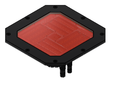
Figure: ULS-ProCopter Transmitter
A transmitter is a device placed on the ground (platform, moving object). It emits a signal in the Infrared range and serves as a kind of beacon. Transmitter marks position for drone landing.
The primary function of the transmitter is to continuously send out a coded signal that can be detected and interpreted by the receiver unit onboard the ULS-ProCopter. This signal contains critical information needed for the operation of the ULS-ProCopter, such as positional data, commands, and system status.
Receiver (Onboard Unit)
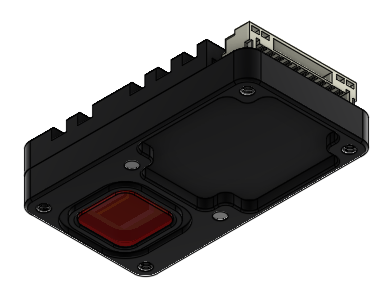
Figure: ULS-ProCopter Receiver
A receiver is a device that is placed on board an aircraft.
The receiver decodes this signal to derive flight information such as positional coordinates, real-time transmitter status updates, and landing guidance. It interprets the data to navigate accurately and ensure drone follows the intended flight path. It provides feedback to the autopilot systems, such as Ardupilot and PX4, to adjust the flight parameters as needed for optimal and safety landing or hovering above.
Part Numbering
| Part Number | Description |
|---|---|
| ULS-ProCopter | System set with 1 receiver. |
| ULS-ProCopter-MRX | System set with 2 receivers. |
| ULSDV-PC-TX | Transmitter unit. Generation 2. |
| ULSDV-PC-RX | Receiver unit. Generation 2. |
| GHR-10V-S | 10 Pin Connector for receiver. Cable side. Manufacturer, JST Commercial. |
| SA810/P8IIB | 8 Pin Connector for transmitter. Cable side. Manufacturer, Weipu Connector. |
| SA610/P4IB | 4 Pin Connector for transmitter. Cable side. Manufacturer, Weipu Connector. |
Table: ULS-ProCopter Part Numbers and Descriptions
System specification.
Common specification:
| Parameter | Value |
|---|---|
| Distance range m.: | 0.1 - 20.0 |
| Working angle (deg): | >100 |
| Data update frequency (Hz): | 20 |
Table: Common System Specifications Receiver (on board unit):
| Parameter | Value |
|---|---|
| Field of view (deg): | 100 |
| Dimensions mm : | 18.4 x 33.4 x 6.9 |
| Weight g.: | 10 |
| Power Consumption (W): | 0.3 |
| Voltage supply (V): | 5.0 |
| Interfaces: | USB, CAN, UART |
Table: Receiver Specifications Transmitter (on ground)
| Parameter | Value |
|---|---|
| Field of emitting (deg): | >100 |
| Dimensions mm. : | 183 x 183 x 29 |
| Weight g.: | 1200 |
| Power Consumption (W): | 18.4 |
| Voltage supply (V): | 12V- 27V |
| Interfaces : | USB, CAN, UART |
Table: Transmitter Specifications
Pinout information
Transmitter pinout
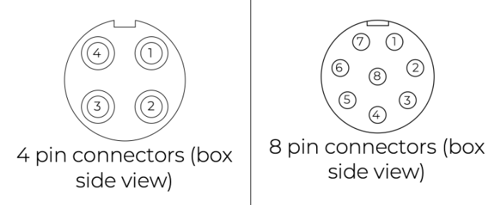
Figure: ULS-ProCopter Transmitter Pinout Diagram
| Pin number | ProCopter |
|---|---|
| 1 | Vcc Input (+12.0V..+27V) |
| 2 | CAN2 H |
| 3 | CAN2 L |
| 4 | UART TX |
| 5 | UART RX |
| 6 | USB D- |
| 7 | USB D+ |
| 8 | GND |
Table: Transmitter 8-pin Main Connector Pinout
| Pin number | ProCopter |
|---|---|
| 1 | +5V Output |
| 2 | CAN1 H |
| 3 | CAN1 L |
| 5 | GND |
Table: Transmitter 4-pin Connector Pinout
Receiver pinout
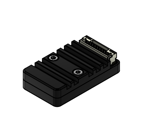
Figure: Receiver Top Side Connector Variant
Figure: Receiver Strait Variant
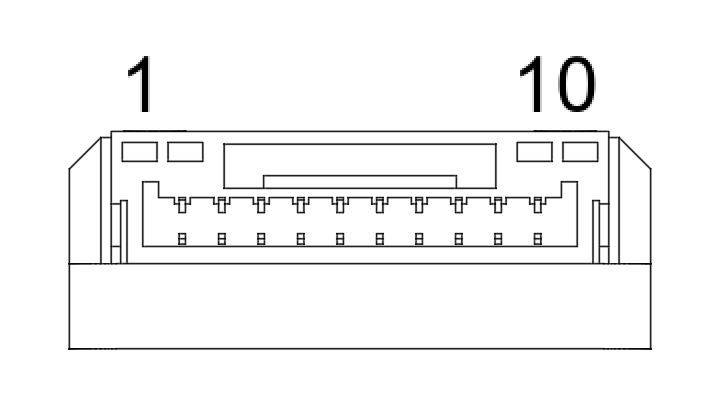
Figure: ULS-ProCopter Receiver connector
| Pin number | Strait Variant | Top Side Connector Variant |
|---|---|---|
| 1 | +5V Input | GND |
| 2 | UART RX | UART2 TX |
| 3 | UART TX | UART2 RX |
| 4 | CAN H | USB D+ |
| 5 | CAN L | USB D- |
| 6 | USB D- | CAN L |
| 7 | USB D+ | CAN H |
| 8 | UART2 RX | UART TX |
| 9 | UART2 TX | UART RX |
| 10 | GND | +5V Input |
Table: Receiver JX1 Connector Pinout (External Power and Control)
Mechanical dimensions
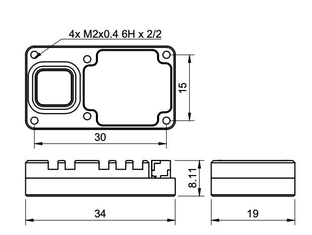
Figure: ULS-ProCopter Receiver dimensions
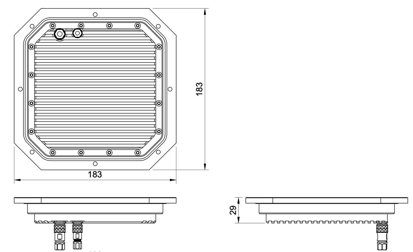
Figure: ULS-ProCopter Transmitter Mechanical Dimensions
System performance characteristics
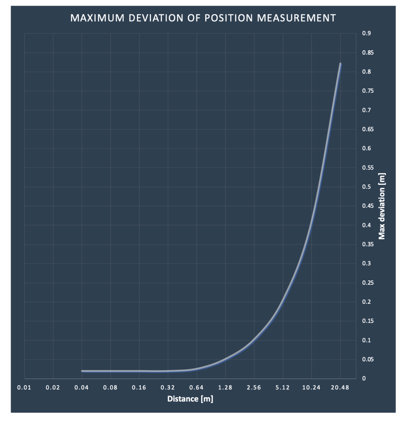
Environmental Conditions - Industrial Grade
Equipment is designed to operate reliably in demanding environmental conditions typical of aerospace, industrial automation, and outdoor applications.
Operating Temperature Range
- Standard operating range: -20°C to +55°C
- Covers most industrial and outdoor applications
- Reliable performance across temperature extremes
- No performance degradation within specified range
Humidity Tolerance
- Relative humidity: Up to 70% (non-condensing)
- Protected against moisture in typical operating conditions
- Suitable for outdoor and semi-protected installations
- Condensation prevention through sealed design
Ingress Protection
- IP67 rated (Dust tight and water immersion resistant)
- 6 - Complete protection against dust ingress
- 7 - Protected against temporary immersion in water (up to 1 meter depth for 30 minutes)
- Suitable for harsh industrial environments
- Protected against rain, splashing, and temporary submersion
- Dust-tight sealing for contaminated environments
Storage Conditions
- Storage temperature: -40°C to +70°C
- Relative humidity: Up to 95% (non-condensing)
- Long-term storage in industrial facilities
Operational Environment Standards
- Designed to meet industrial equipment requirements
- Suitable for UAV/drone applications
- Outdoor installation capable
- Protected against:
- Dust and particulate matter
- Water spray and rain
- Temporary water immersion
- Temperature fluctuations
- High humidity
Change Control
All changes to this document must be reviewed and approved by the relevant technical leads and stakeholders
2 - ULS-ProCopter Interface Control Document
ULSDC-PBICD070425 · version 1.0.0 · issued June 10, 2025
The numbered PDF is the controlled copy: download it from the portal.
Introduction
Purpose
This document outlines the interfaces between the ULS-ProCopter system components, including the transmitter, receiver, and autopilot systems (Ardupilot and PX4 and similar).
Scope
This document is intended for use by system engineers, integrators, and developers working with ULS-ProCopter systems. It provides detailed information on the interfaces between the system components, ensuring seamless integration and operation.
System Components
Transmitter (Ground Unit)
Figure: ULS-ProCopter Transmitter
A transmitter is a device placed on the ground (platform, moving object). It emits a signal in the Infrared range and serves as a kind of beacon. Transmitter marks position for drone landing.
The primary function of the transmitter is to continuously send out a coded signal that can be detected and interpreted by the receiver unit onboard the ULS-ProCopter. This signal contains critical information needed for the operation of the ULS-ProCopter, such as positional data, commands, and system status.
Receiver (Onboard Unit)
Figure: ULS-ProCopter Receiver
A receiver is a device that is placed on board an aircraft.
The receiver decodes this signal to derive flight information such as positional coordinates, real-time transmitter status updates, and landing guidance. It interprets the data to navigate accurately and ensure drone follows the intended flight path. It provides feedback to the autopilot systems, such as Ardupilot and PX4, to adjust the flight parameters as needed for optimal and safety landing or hovering above.
Interface Overview
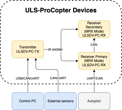
Figure: ULS-ProCopter System Interface Overview
Transmitter to control PC interface (external sensors):
Data Type:
- Status information
- Control signals
- Transmitter configuration
- External IMU/COMPASS data
Connection Types
- CAN Bus - For network communication
- USB - For configuration and firmware updates
- UART - For serial communication with external sensors
Pinout:
Figure: ULS-ProCopter Transmitter Pinout Diagram
| Pin number | ProCopter |
|---|---|
| 1 | Vcc Input (+12.0V..+27V) |
| 2 | CAN2 H |
| 3 | CAN2 L |
| 4 | UART TX |
| 5 | UART RX |
| 6 | USB D- |
| 7 | USB D+ |
| 8 | GND |
Table: Transmitter 8-pin Main Connector Pinout
| Pin number | ProCopter |
|---|---|
| 1 | +5V Output |
| 2 | CAN1 H |
| 3 | CAN1 L |
| 5 | GND |
Table: Transmitter 4-pin Connector Pinout
Transmitter to Receiver Interface:
The transmitter and receiver use an optical interface to exchange data. Transmission use IR emission 940 nanometers. Data transmission is only in the direction from the transmitter to the receiver.
Data Type:
- Position encoded
- Status encoded data (Transmitter orientation and instructions)
Connection Type
- Optical IR 940nm - Infrared optical link
Receiver to Autopilot and Receiver to PC Interfaces
Data Type:
- Mavlink messages
- ULS-Blitz frames
- ASCII protocol
Connection Types
- UART - Serial communication with autopilot
- CAN - Network communication
- USB - Direct PC connection
Pinout:
Figure: Receiver Top Side Connector Variant
Figure: Receiver Strait Variant
Figure: ULS-ProCopter Receiver connector
| Pin number | Strait Variant | Top Side Connector Variant |
|---|---|---|
| 1 | +5V Input | GND |
| 2 | UART RX | UART2 TX |
| 3 | UART TX | UART2 RX |
| 4 | CAN H | USB D+ |
| 5 | CAN L | USB D- |
| 6 | USB D- | CAN L |
| 7 | USB D+ | CAN H |
| 8 | UART2 RX | UART TX |
| 9 | UART2 TX | UART RX |
| 10 | GND | +5V Input |
Table: Receiver JX1 Connector Pinout (External Power and Control)
Powering Interfaces
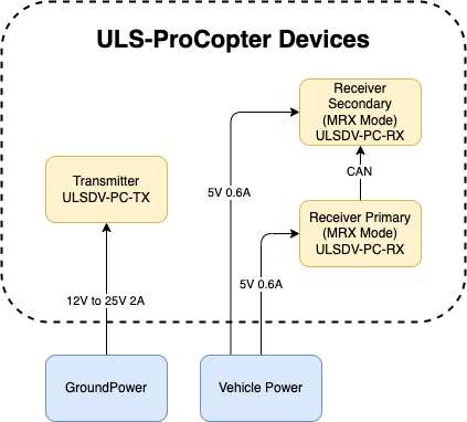
Figure: ULS-ProCopter Powering Interfaces and Electrical Characteristics
Transmitter Electrical Characteristics
- Supply Voltage: 12.0V - 25V
- Supply Current: 2A
- Power Consumption: 18.1 W
Receiver Electrical Characteristics
- Supply Voltage: 5.0V
- Supply Current: 0.6A
- Power Consumption: 3 W
Functional Interfaces

Figure: ULS-ProCopter Functional Interfaces and Data Flow
Data Exchange
- Control PC used to configure and view status of transmitter.
- Control PC used to set configuration of receivers.
- Control PC (or embedded equipment instead control pc) can be used to send control signals (On/off, compass override information)
- External IMU/Compass equipment can be used to override internal IMU/compass information.
- Receiver accept data from transmitter over IR signal. This data include position field information and ground unit IMU data.
- Receiver accept NED and Attitude information from autopilot to be able convert coordinate system that can be accepted by autopilot.
- Several Receivers can communicate to be able calculate vehicle orientation YAW.
- Receiver send position offset data to autopilot.
Mechanical interfaces
Transmitter mechanical interface:
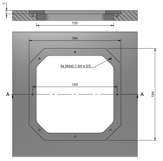
Figure: ULS-ProCopter Transmitter Mechanical Interface and Mounting Dimensions
Receiver mechanical interface:
Figure: ULS-ProCopter Receiver Mechanical Interface and Mounting Dimensions
Environmental Conditions - Industrial Grade
Equipment is designed to operate reliably in demanding environmental conditions typical of aerospace, industrial automation, and outdoor applications.
Operating Temperature Range
- Standard operating range: -20°C to +55°C
- Covers most industrial and outdoor applications
- Reliable performance across temperature extremes
- No performance degradation within specified range
Humidity Tolerance
- Relative humidity: Up to 70% (non-condensing)
- Protected against moisture in typical operating conditions
- Suitable for outdoor and semi-protected installations
- Condensation prevention through sealed design
Ingress Protection
- IP67 rated (Dust tight and water immersion resistant)
- 6 - Complete protection against dust ingress
- 7 - Protected against temporary immersion in water (up to 1 meter depth for 30 minutes)
- Suitable for harsh industrial environments
- Protected against rain, splashing, and temporary submersion
- Dust-tight sealing for contaminated environments
Storage Conditions
- Storage temperature: -40°C to +70°C
- Relative humidity: Up to 95% (non-condensing)
- Long-term storage in industrial facilities
Operational Environment Standards
- Designed to meet industrial equipment requirements
- Suitable for UAV/drone applications
- Outdoor installation capable
- Protected against:
- Dust and particulate matter
- Water spray and rain
- Temporary water immersion
- Temperature fluctuations
- High humidity
Change Control
All changes to this document must be reviewed and approved by the relevant technical leads and stakeholders
3 - ULS-ProCopter Operation Manual
ULSDC-PBOM070425 · version 1.0.0 · issued June 14, 2025
The numbered PDF is the controlled copy: download it from the portal.
Introduction
Purpose
The purpose of this operation manual is to provide comprehensive guidance on the installation, configuration, operation, and troubleshooting of the ULS-ProCopter System. This manual is designed to help users effectively integrate and utilize the system for precision landing and navigation applications.
Scope
This document is intended for use by system engineers, integrators, operators, and developers working with ULS-ProCopter systems. It provides detailed information on system operation, configuration procedures, and integration with autopilot systems.
System Base Components
Transmitter (Ground Unit)
Figure: ULS-ProCopter Transmitter
A transmitter is a device placed on the ground (platform, moving object). It emits a signal in the Infrared range and serves as a kind of beacon. Transmitter marks position for drone landing.
The primary function of the transmitter is to continuously send out a coded signal that can be detected and interpreted by the receiver unit onboard the ULS-ProCopter. This signal contains critical information needed for the operation of the ULS-ProCopter, such as positional data, commands, and system status.
Receiver (Onboard Unit)
Figure: ULS-ProCopter Receiver
A receiver is a device that is placed on board an aircraft.
The receiver decodes this signal to derive flight information such as positional coordinates, real-time transmitter status updates, and landing guidance. It interprets the data to navigate accurately and ensure drone follows the intended flight path. It provides feedback to the autopilot systems, such as Ardupilot and PX4, to adjust the flight parameters as needed for optimal and safety landing or hovering above.
Operation theory
All data communication from the transmitter to the receiver is done in the optical band, which eliminates interference with other radio devices and radio signals.
The transmitter contains an array of emitting elements that operate in the infrared range. The transmitter emits a modulated signal with each of the transmitter emitters transmitting a unique signal. Each of the transmitter emitters emits in a unique direction. The receiver receives the signal from the transmitter decodes it and by analyzing the signal can determine in which direction relative to the transmitter it is located. The distance to the transmitter is determined by the signal strength. Thus the system determines the position in a polar coordinate system with the origin at the center of the transmitter.
It is worth noting that due to the features described above, the receiver position readings will change when the transmitter orientation is changed, but the change in receiver orientation will have no effect if the transmitter and receiver are within the range of visibility of the systems specified in the specification.
This must be taken into account when working with the system. In order to calculate the position of the receiver without errors in case of orientation changes, the transmitter is equipped with an inertial orientation measurement system. This system allows you to determine the orientation of the module and transmit this information to the receiver by means of an infrared signal so that it can correct the position according to the inclination of the transmitter (transmitter level correction function).
The system can then convert the polar coordinate system to a Cartesian coordinate system. In this case, this coordinate system originates at the center of the transmitter.
Usually, to navigate and ensure a precise landing, the autopilot needs information about the position of the landing point in a coordinate system either attached to the drone’s body or in a global coordinate system.
The system can then convert the polar coordinate system to a Cartesian coordinate system. In this case, this coordinate system originates at the center of the transmitter.
To navigate and ensure a precise landing, the autopilot needs information about the position of the landing point in a coordinate system either attached to the drone’s body or in a global coordinate system. For this purpose, the receiver requests information from the autopilot about its position and orientation. Then, using this information and information about the orientation of the ground transmitter, the receiver can calculate the position of the transmitter relative to the drone in the required coordinates.
It important to point out that the system will act as a navigation sensor. The information from our system can be used by autopilots and drones for various purposes:
- Landing vehicle on platform
- Hovering over a point of interest
- Accurately dropping a load or precisely lowering it on a tether.
Functional description diagram
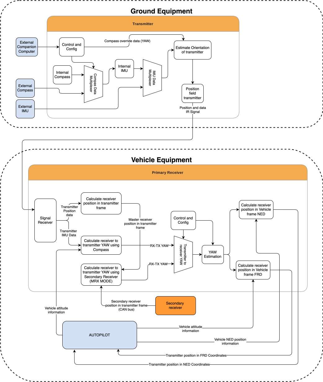
System specification.
Common specification:
| Parameter | Value |
|---|---|
| Distance range m.: | 0.1 - 20.0 |
| Working angle (deg): | >100 |
| Data update frequency (Hz): | 20 |
Table: Common System Specifications Receiver (on board unit):
| Parameter | Value |
|---|---|
| Field of view (deg): | 100 |
| Dimensions mm : | 18.4 x 33.4 x 6.9 |
| Weight g.: | 10 |
| Power Consumption (W): | 0.3 |
| Voltage supply (V): | 5.0 |
| Interfaces: | USB, CAN, UART |
Table: Receiver Specifications Transmitter (on ground)
| Parameter | Value |
|---|---|
| Field of emitting (deg): | >100 |
| Dimensions mm. : | 183 x 183 x 29 |
| Weight g.: | 1200 |
| Power Consumption (W): | 18.4 |
| Voltage supply (V): | 12V- 27V |
| Interfaces : | USB, CAN, UART |
Table: Transmitter Specifications
Pinout information
Transmitter Pinout
Figure: ULS-ProCopter Transmitter Pinout Diagram
| Pin number | ProCopter |
|---|---|
| 1 | Vcc Input (+12.0V..+27V) |
| 2 | CAN2 H |
| 3 | CAN2 L |
| 4 | UART TX |
| 5 | UART RX |
| 6 | USB D- |
| 7 | USB D+ |
| 8 | GND |
Table: Transmitter 8-pin Main Connector Pinout
| Pin number | ProCopter |
|---|---|
| 1 | +5V Output |
| 2 | CAN1 H |
| 3 | CAN1 L |
| 5 | GND |
Table: Transmitter 4-pin Connector Pinout
Receiver Pinout
Figure: Receiver Top Side Connector Variant
Figure: Receiver Strait Variant
Figure: ULS-ProCopter Receiver connector
| Pin number | Strait Variant | Top Side Connector Variant |
|---|---|---|
| 1 | +5V Input | GND |
| 2 | UART RX | UART2 TX |
| 3 | UART TX | UART2 RX |
| 4 | CAN H | USB D+ |
| 5 | CAN L | USB D- |
| 6 | USB D- | CAN L |
| 7 | USB D+ | CAN H |
| 8 | UART2 RX | UART TX |
| 9 | UART2 TX | UART RX |
| 10 | GND | +5V Input |
Table: Receiver JX1 Connector Pinout (External Power and Control)
Mechanical dimensions
Figure: ULS-ProCopter Receiver dimensions
Figure: ULS-ProCopter Transmitter Mechanical Dimensions
Integration
Ground unit installation (transmitter)
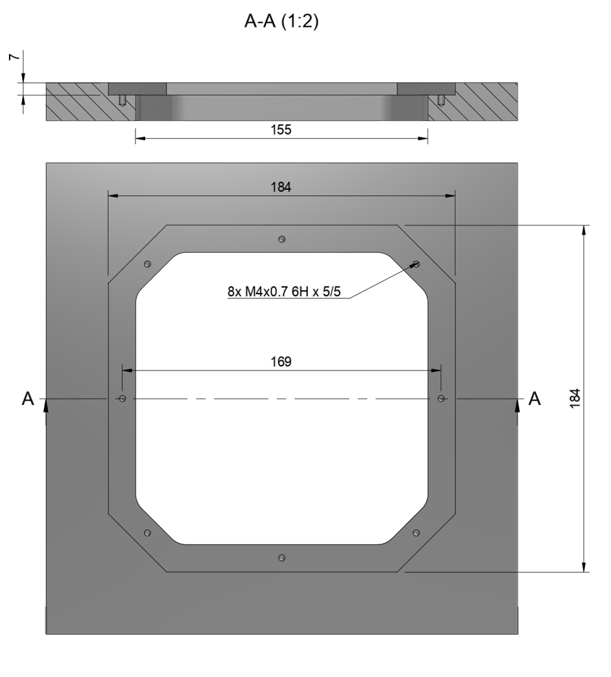
The device must be installed on a clean surface to avoid any obstacles. The device must be installed in an open area. There must be no obstacles in the radiation field of the transmitting device. If possible, avoid installing the system near vertical surfaces that can strongly reflect infrared radiation. Device developed to be installed in panel and bolted with M4 screw. All customers get 3d model of system and cut panel as reference to make integration process more simple.
Panel cut-out drawing.
After installation, it is recommended to verify the correctness of the compass reading and, if necessary, correct the compass calibration.
Wiring Transmitter
The transmitter only requires power to operate. The transmitter can be powered via a 8-pin connector located nearby. External compass (IMU) and control data can be send over UART and CAN protocol. See pinout information of transmitter.
Configure transmitter in ULS-Tools
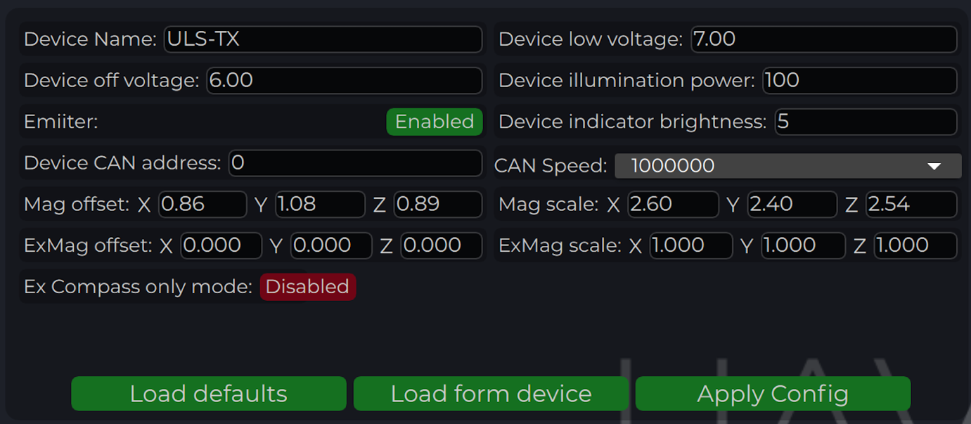
| Parameter | Description |
|---|---|
| Device name | Name of the device displayed in main window |
| Device low voltage | Voltage limit to start indicator flash warning |
| Device off voltage | Voltage limit to disable IR emitters to prevent battery under discharge |
| Device illumination power | Emitters power correction (100 for normal operation) |
| Emitter (enable/disable) | Disable (for configure) or enable emitter |
| Device Indicator Brightness | Adjust transmitter RGB led indicator brightness |
| Device CAN address/speed | Setup external CAN interface parameters |
| Compass Override (enable/disable) [deg] | Enable in case of module installed on fixed platform. The entered value will be used instead of internal compass data in “Compass mode”. In this way, the transmitter must be turned on the corresponding angle, CW to North. |
| Mag(ExMag) offset/scale | Calibration parameters for internal/external magnetometer |
| ExCompass mode only | If enabled - system will not use internal compass. If external compass data unavailable system generate error. If disabled internal compass will be used if External magnetometer unavailable |
Table: Transmitter Configuration Parameters
Compass calibration
This compass is used to calculate an absolute heading of the ground unit. This information is transmitted to the Receiver and used to calculate NED coordinates. To be able to use compass, it needs to be calibrated before. To calibrate compass:
- Press “Reset calibrations”.
- Rotate device in different directions until you get 3 circles on charts (see picture below).
- Press “Apply calibration” & “Apply configuration”.
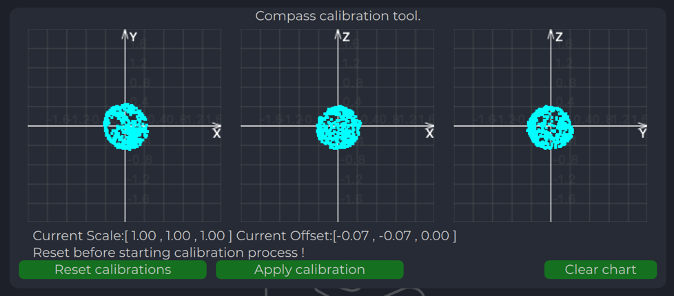
Compass chart after calibration:
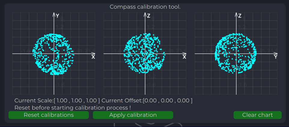
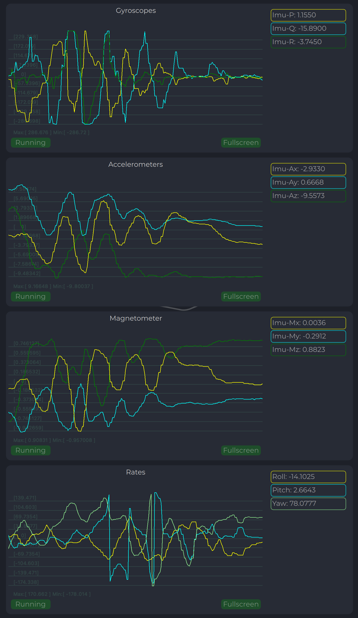
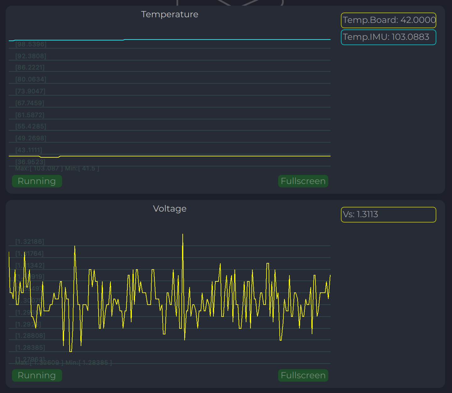
Charts Transmitter
Program display several parameters of the device on charts:
- IMU data.
- Voltage (not valid when powered from USB).
- Temperature data.
Led Indicator
You can check the status of the transmitter looking on the LED indicator on the transmitter. LED flashes in sequences of colors, so it can flash green-red-off-off or green-off-blue-off.
| Flash color | Description |
|---|---|
| Green | Normal operation. |
| Orange | Low voltage. |
| Red | Problem, check device. If it is first in sequence it can be led malfunctions of power voltage below minimum, second for compass fail detect. |
| Blue | Compass ok and device points to the North (brightness of illumination depends on how precise it is pointed to the North). |
Table: LED Indicator Status Colors
On-board unit installation (receiver)
The receiver can be installed both inside and outside the vehicle. However, please note that this version of the system is not equipped with protection against moisture and dust. The orientation of the receiver does not matter - however, when installing the receiver, care should be taken to ensure line-of-sight conditions between the transmitter and receiver throughout the entire field of view of the receiver (100 deg). The receiver sensor zone is indicated in the figure.
Once the receiver is installed, enter the appropriate receiver offset information into the configuration.
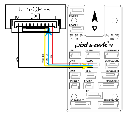
Wiring Receiver Pixhawk 4 autopilot connection using UART
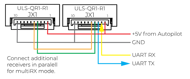
Wiring for MultiRX mode (MRX)
Configure Receiver in ULS-Tools
Note:
To apply any changes, press “Apply Config” button at the bottom of the field.
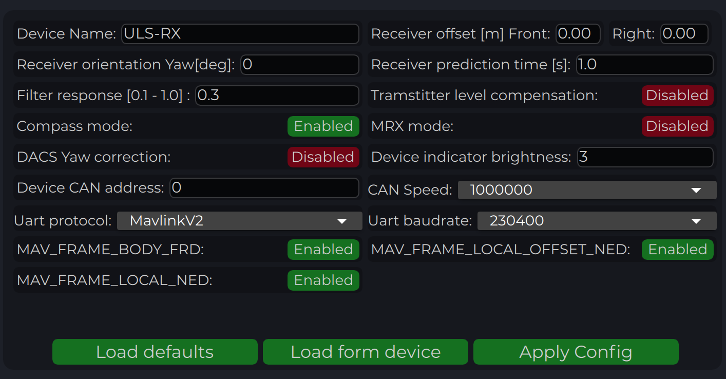
| Parameter | Description |
|---|---|
| Device name | Name of the device displayed in main window. |
| Receiver offset (Front, Right) [m] | Location of receiver in the drone (in meters). This configuration used to calculate drone heading in MultiRX mode. |
| 2Receiver prediction time [s] | Prediction time is used to send prediction information of landing position. It is useful to avoid the effect of short terms signal interruptions. Generally, its value can be set from 0.3 up to 1 sec. |
| Filter response | Set response for internal position filter of receiver. Hi values make lag time shorter, lower values smooth position information. |
| Transmitter level compensation | Used to compensate Pan-Tilt rotations of the transmitter. It is used in case of landing on the moving objects. |
| Noise debug | Use this function to check the noise interference with other devices. In this mode, receiver do not receive the signal from the transmitter, but can capture all the other signals. At the time of the test, transmitter must be switched off, and you can see on Signal Viewer the level of noise and detect what devices around affect the receiver. In general, max level of noise needs to be lower than 0.0025 for Beans B channel. NO OPERATIONS CAN BE PERFORMED IF THIS OPTION IS ENABLED - switch off before the normal use. |
| Compass mode (disable/enable) | If settings are disabled - receiver will not perform data calculation based on ground compass data. Multi RX mode and (or) compass mode must be enabled to allow the operation. |
| MRX mode (disable/enable) | If settings are enabled - receiver will use secondary receiver to perform the data calculation. Multi RX mode and (or) compass mode must be enabled to allow the operation. |
| Device Indicator Brightness | Adjust transmitter led indicator brightness |
| Device CAN address/speed | Setup external CAN interface parameters |
| UART Protocol | Select corresponding protocol to communicate with autopilot. If protocol “MavlinkV2” is selected, you can enable the corresponding MAV_FRAME message to be sent to the autopilot (Ardupilot - MAV_FRAME_BODY_FRD and PX4 MAV_FRAME_LOCAL_NED for now) |
| UART baud rate | Select UART communication speed. |
Table: Receiver Configuration Parameters
Status Information field
In the status display area, you can check the status of the receiver and visualise the position of the receiver relative to the drone.
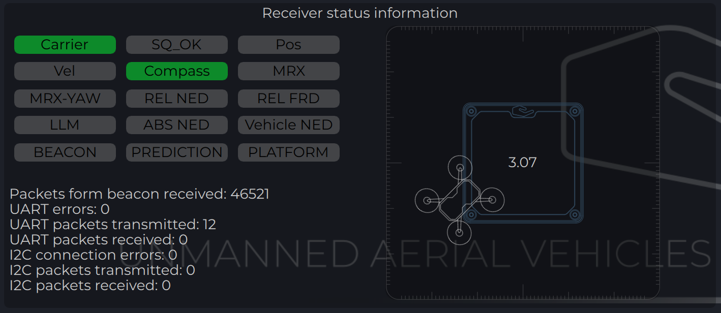
| Parameter | Description |
|---|---|
| Carrier | The carrier signal from transmitter is detected. |
| SQ_OK | Signal quality of the carrier is ok. |
| Pos | RAW sensor position is estimated. |
| Vel | RAW sensor velocity. |
| Compass | Ground unit orientation is received. |
| MRX | Secondary sensor for MRX mode is connected and sending data. |
| MRX-YAW | Yaw orientation is calculated using MRX. |
| REL-NED | Relative NED position is calculated. |
| REL-FRD | Relative FRD position is calculated. |
| LLM | Lat Lon Msl position is available (reserved for future options). |
| ABS-NED | Absolute position of transmitter is available. |
| VEHICLE-NED | Absolute position of vehicle is provided by the autopilot (used to calculate ABS position data). |
| BEACON | Indicate System Ok state. |
| PREDICTION | Indicate when system uses predicted information for the calculation. |
| PLATFORM | Position of landing platform is provided by third party devices. |
Table: Receiver Status Information Fields
Setup MRX mode
This option enables to use data from two receivers to calculate position. It allows calculating receiver yaw orientation using triangular method. In this mode, compass data (on ground and on board) is not affecting the position estimation, so it is more durable way to land. In this mode the maximum distance is limited by 10 m and at altitude above, it will use compass mode.
To set up and check MRX mode do the following:
- Connect receivers on board with CAN BUS.
- Configure “Receiver offset” for both receivers.
- Configure “Receiver orientation YAW” for both receivers (XCopter-G2).
- Enable option “MRX mode”.
- After set up, hover the drone above the transmitter (1 m - 2 m) and check that Tdistance and Distance are the same (+/- 20%).
- Correct “Receiver offset” option in case of TDistance and Distance are not approximately the same. Increasing position between receivers increases Tdistance and backwards.
- Rotate Drove over transmitter (1 m - 2 m) and check the value of the MRX-YAW on chart “GU Orientation”. It needs to be corresponding to the heading of the drone relatively to the transmitter.
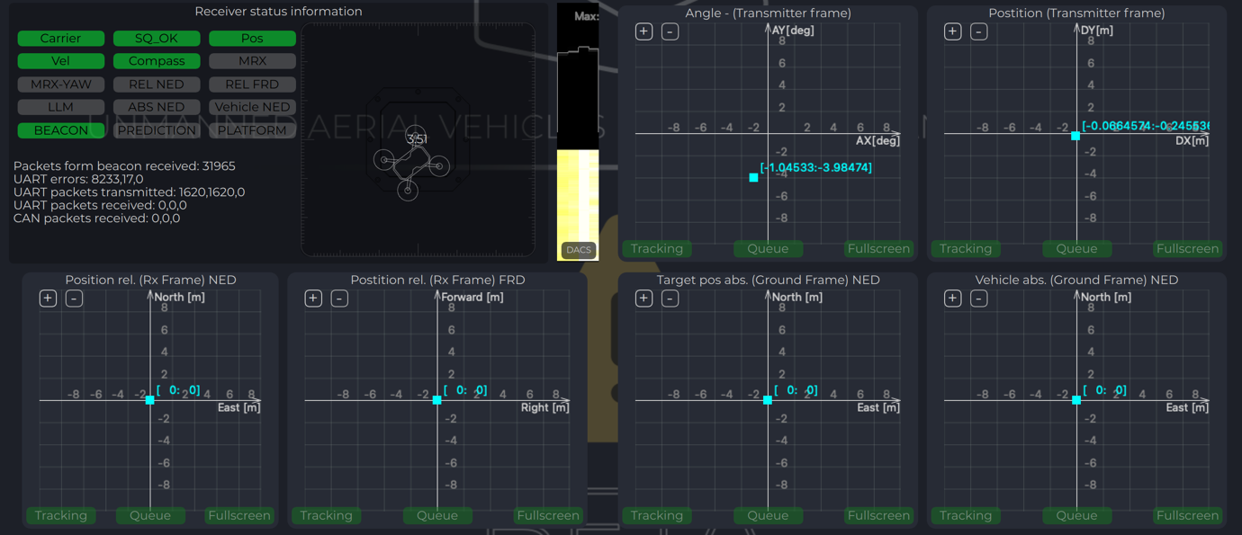
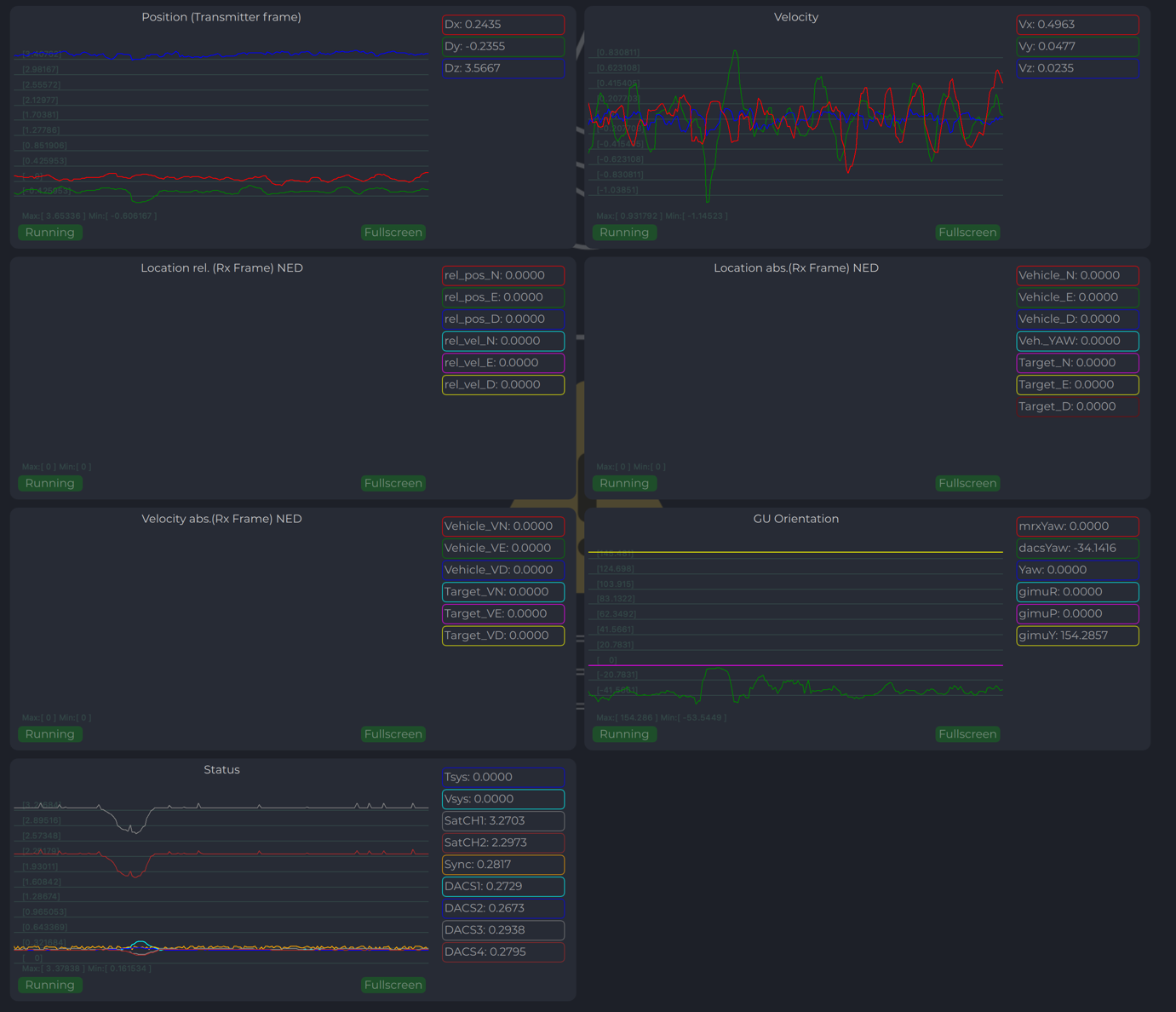
Receiver Charts
Program display several parameters of the device on charts:
- Angles, Positions in different coordinate systems
- Distance
- Vehicle information (position and velocity)
- Data from Transmitters IMU.
Integration instructions for Ardupilot based systems.
Preparing for integration:
- Download the latest version of the ULSTools software. It is recommended to connect all sensors to PC and update the firmware for all UAVLAS devices in the system.
- Update autopilot with Arducopter latest version.
- Configure transmitter.
- Configure receiver.
Example of receiver configuration:
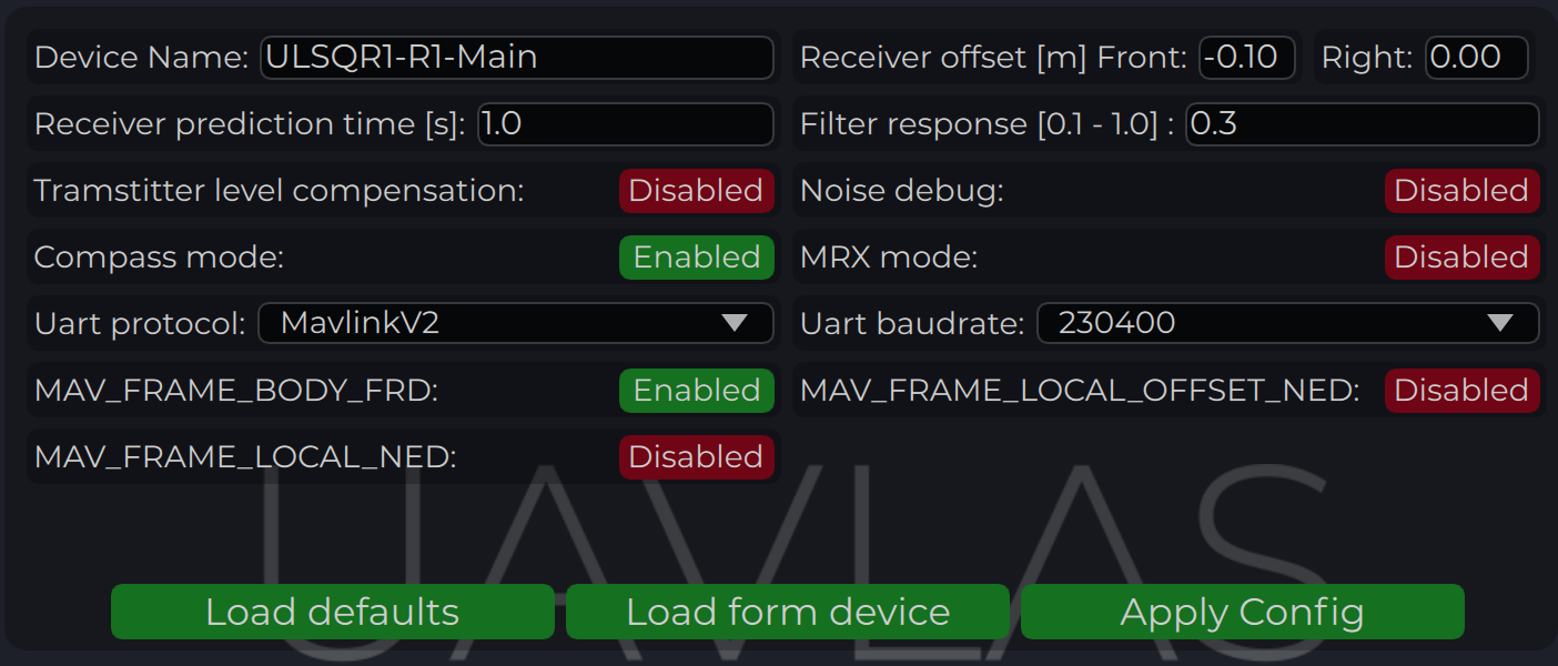
Autopilot configuration
Setup PLND section
| Param | Value | Comment |
|---|---|---|
| PLND_ENABLED | 1 | Enable precision landing module |
| PLND_TYPE | 1 | Use type = 1 to enable UAVLAS sensor over Companion computer driver |
Table: Ardupilot PLND Section Parameters All other parameters in PLND section defaults or use accordingly to your vehicle set up requirements.
On a picture example configuration provided.
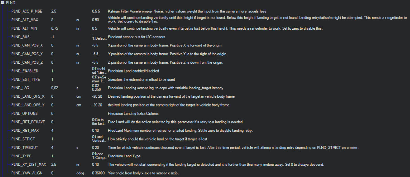
Set up serial communication in SERIALx Section.
| Param | Value | Comment |
|---|---|---|
| SERIAL2_BAUD | 230 | Select baud rate - it needs to be same as in receiver’s configuration. |
| SERIAL2_OPTIONS | 0 | Default |
| SERIAL2_PROTOCOL | 2 | MAVlink2 protocol support. |
Table: Serial Communication Configuration (SERIALx Section) Set up serial communication messages in SRx Section. Sensor requires some data from autopilot to work in different modes.
| Param | Value | Comment |
|---|---|---|
| SR2_EXTRA1 (or MAV2_EXTRA1) | 20 | Stream Attitude information (20Hz) (YAW Orientation is required for sensor in compass mode) |
| SR2_POSITION (or MAV2_POSITION) | 20 | Optional - Stream Vehicle position (20Hz) (LOCAL_POSITION_NED is required for sensor to provide LOCAL position for the target) |
Table: Serial Communication Messages (SRx Section) Check setup.
If all settings are done correct, autopilot has GPS data and receiver in the field of view of the transmitter, you can find LANDING_TARGET message in mavlink inspector (a screenshot from Mission Planner)
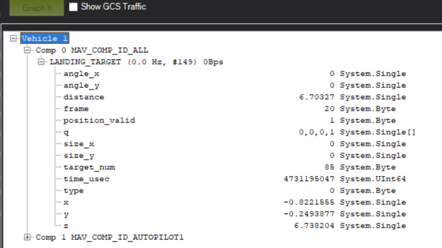
Setup Precision loiter mode.
To enable precision loiter mode you need attach any unused switch to PrecLoiter option see picture below:
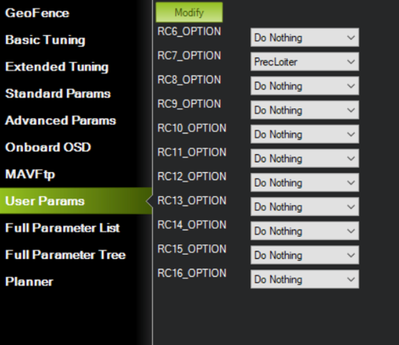
Try to use this switch and you must get messages: “PrecLoiter: LOW” and “PrecLoiter: HIGH” After test flight above target check telemetry - you will find PL data contains offsets form landing target.
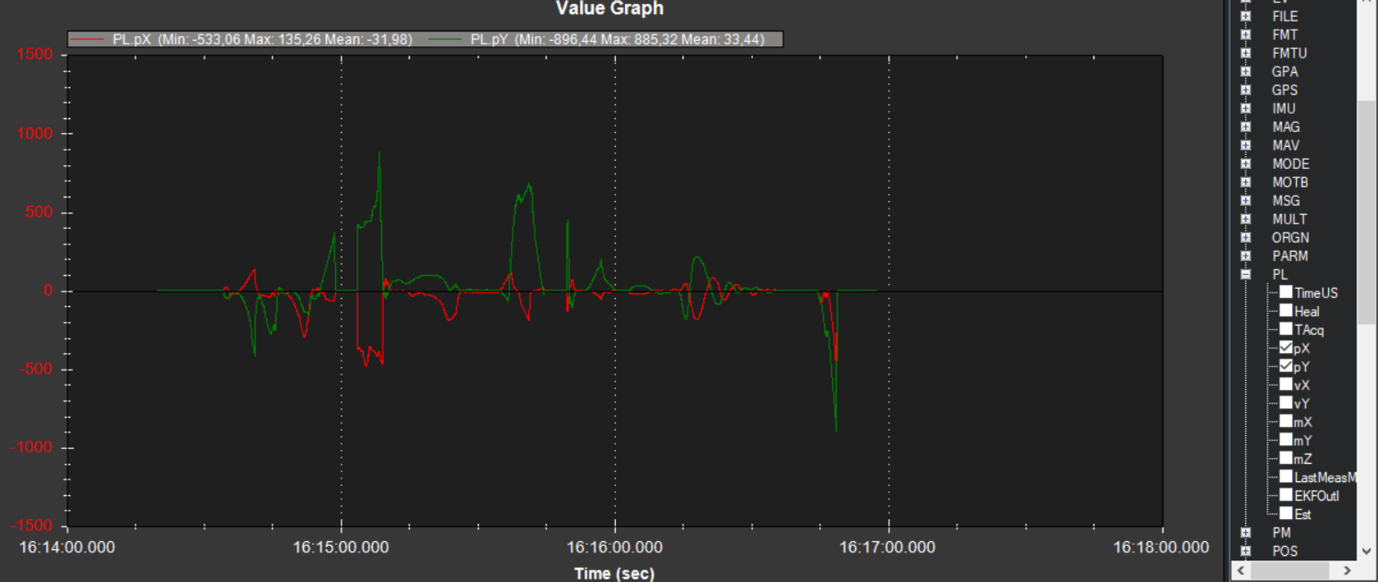
PID tuning
In case of oscillations and other issues at landing stage, pls, check PID parameters of Ardupilot.
It is recommended to check the Position XY, Velocity XY and Loiter speed parameters in “Extended tuning” section to achieve the best performance.
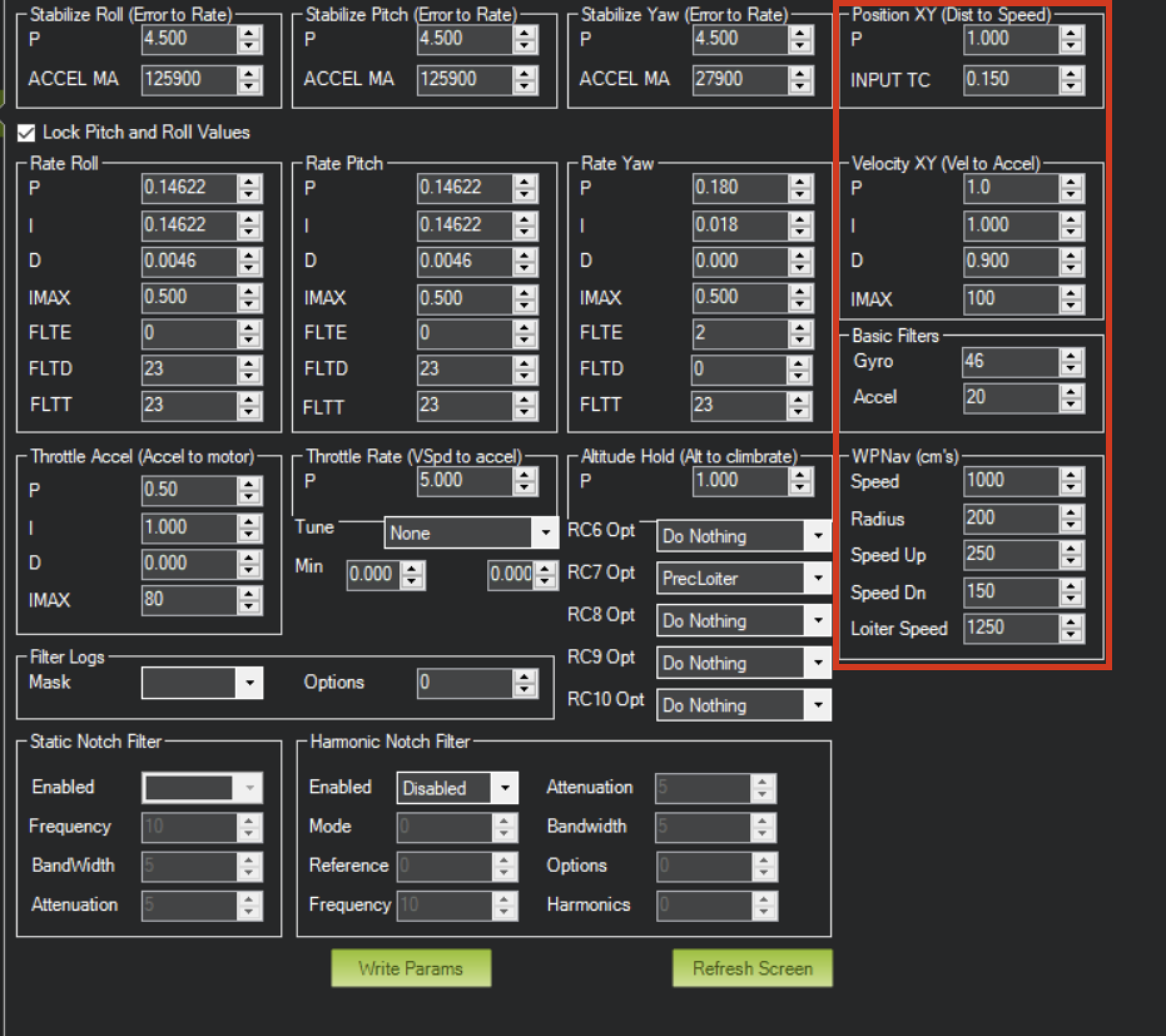
For additional information, see Ardupilot manual.
Integration instructions for PX4 based systems.
Preparing for integration:
- Download the latest version of the ULSTools software. It is recommended to connect all sensors to PC and update the firmware for all UAVLAS devices in the system.
- Update autopilot with PX4 latest version.
- Configure transmitter.
- Configure receiver.
Current version of the system can use MavlinkV2 protocol to communicate with PX4 autopilots (for now it supports MAV_FRAME_LOCAL_NED).
Example of receiver configuration:
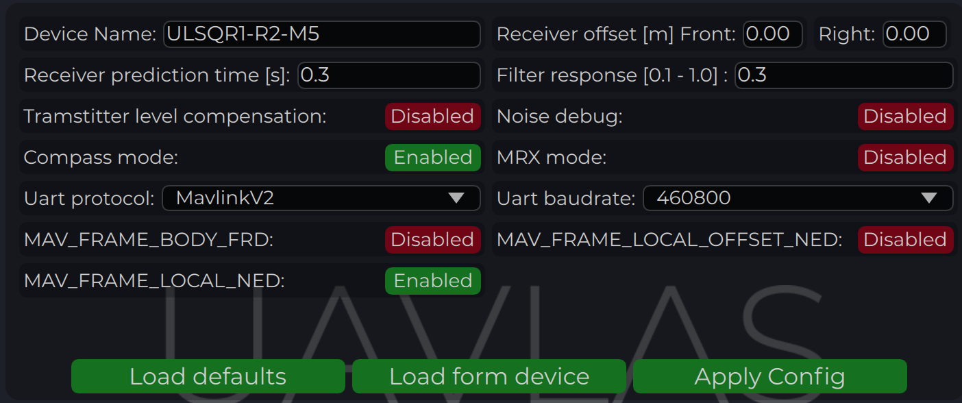
Configure PX4 autopilot.
Values are provided as example (in our case, Pixhawk4-mini AP)
| PX4 Parameter | Value |
|---|---|
| MAV_1_CONFIG | TELEM/SERIAL4 (require reboot to set next params) |
| MAV_1_FORWARD | Enabled. |
| MAV_1_MODE | Onboard. |
| SER_TEL4_BAUD | 460800_8N1 (It needs to be corresponding to the setting of UART in Receiver ULS-QR1-R1 connected to PX4 AP) |
Table: PX4 Autopilot Configuration Parameters
Running and testing
After configuration and wiring, power up drone and transmitter. On QGround control, go “Analyze Tools” -> MAVLINK Inspector. Check LANDING_TARGET MAVLINK message
In case the vehicle provide LOCAL_POSITION_NED message to UAVLAS system, and it hovers over beacon, you get “position_valid = 1” in LANDING_TARGET
To perform precision landing, you need to create a flight plan and enable Precision Landing option on the landing point.
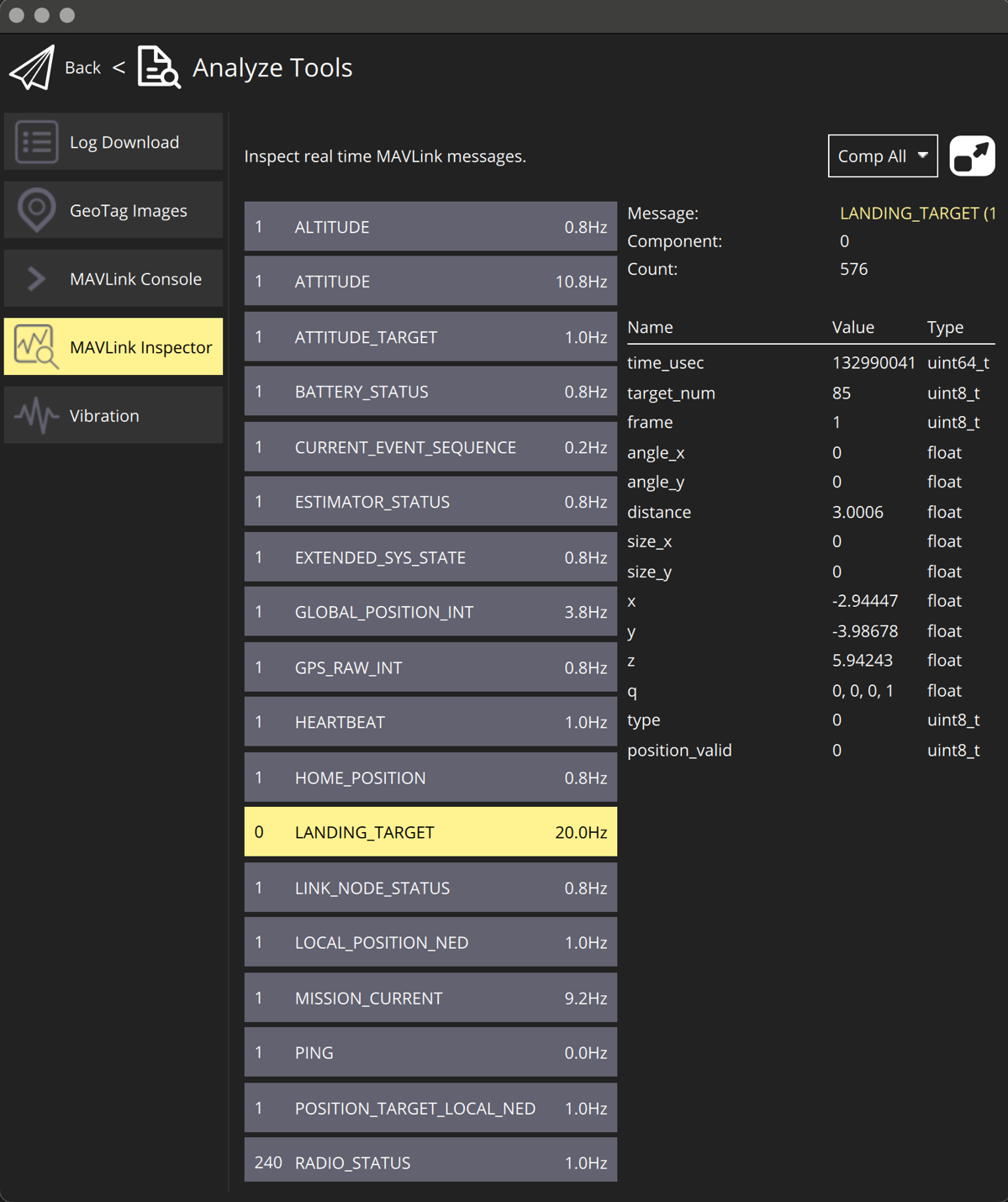
Troubleshooting
Before of all check:
- You are using latest version of ULS-Tools, latest firmware on ULS-XCOPTER transmitter and receiver, and latest Ardupilot (PX4) firmware.
No mavlink message:
- Transmitter are switched on and receiver in field of view of transmitter.
- Red light on receiver flashes fast ( > 5 times per second ). If it flash 2 times per sec it mean that transmitter not switched on, or not in field of view. If it not flash - check power.
- Check Serial setting on AP params and on receiver be sure you are set EXTRA params for corresponding serial port on AP.
- Check wiring power and RX, TX (see pinouts and wiring diagram)
- Check on receiver that MAV_FRAME_BODY_FRD (MAV_FRAME_LOCAL_NED) enabled.
Not holding in precision loiter mode but mavlink message ok:
- Check that you setup Precision loiter mode on AP
Circular motions during landing:
- Check compass calibration on ground unit.
- Check Compass calibration on AP.
- Check magnetic interference on ground.
- Use compass override mode to debug landing.
- Check precision landing PID settings.
The landing is not precise enough:
- Check the position control PID settings of AP.
- For Ardupilot check Kalman filter settings.
- Check filter smoothness param on receiver.
- Check trajectory Jerk settings on AP.
Change Control
All changes to this document must be reviewed and approved by the relevant technical leads and stakeholders
4 - ULS-ProCopter Precision Landing System
ULSDC-PBFL070425-L · version 1.0.0 · issued 2025-11-11
The numbered PDF is the controlled copy: download it from the portal.
ULS-ProCopter Precision Landing System
Ultra-Compact Infrared UAV Landing Solution | 20m Range | Lightweight Design | -40°C to +85°C

Why Choose ULS-ProCopter?
✓ 20m Operating Range | ✓ Ultra-Compact Design | ✓ No Radio Connection Required | ✓ 20Hz Update Rate | ✓ Plug & Play Integration| ✓ Industrial Temperature Range
Next-generation precision landing technology for lightweight UAVs and multi-copters requiring accurate positioning and safe autonomous landing on stationary or moving platforms. The ULS-ProCopter system enables precise autonomous UAV landing through advanced infrared positioning technology. The system consists of a compact ground-based transmitter that emits coded infrared signals, and ultra-lightweight onboard receivers that calculate real-time position and orientation data.
How It Works
- Ground Transmitter (TX) - Compact infrared beacon continuously emits coded positioning signals in a >100° cone
- Onboard Receiver (RX) - Ultra-lightweight unit mounted on UAV decodes signals and calculates 6DOF position (X, Y, Z, Roll, Pitch, Yaw)
System Components
| Component | Size (mm) | Weight | FOV/Angle | Power | Details |
|---|---|---|---|---|---|
| Transmitter | 183×183×29 | 1200g | >100° emit | 18.4W, 12-27V | Ultra-compact ground beacon |
| Receiver | 18.4×33.4×6.9 | 10g | 100° | 0.3W, 5V | Miniature receiver with integrated processing |
Communication: USB, CAN, UART (115200 baud) | Autopilot Support: Ardupilot, PX4, Custom integration
Data Output: Position (X/Y/Z), Orientation (Roll/Pitch/Yaw), Signal quality, System status
Technical Specifications
Performance
| Feature | Value | Notes |
|---|---|---|
| Operating Range | 0.1 - 20m | Optimal performance throughout range |
| Update Rate | 20Hz | Real-time position updates |
| Accuracy | ±5cm | Consistent across operating range |
| Latency | <50ms | End-to-end signal processing |
| Transmitter Angle | >100° cone | Wide coverage landing zone |
| Receiver FOV | 100° | Wide field of view for approach |
| Operating Temp | -40°C to +85°C | Extended industrial grade |
| Storage Temp | -40°C to +85°C | Same as operating range |
| Protection | IP40 | Suitable for indoor/outdoor use |
| Weight Penalty | 10g | Ultra-lightweight receiver |
Applications & Use Cases
Primary Applications
🚁 Multi-copter Landing - Precision landing for lightweight drones and racing quadcopters
📦 Delivery Drones - Accurate package delivery to designated landing zones
🏭 Industrial Inspection - Reliable landing for confined spaces and structures
🎬 Cinematography - Precise positioning for aerial filming and photography platforms
Key Benefits
- Ultra-Lightweight - Only 10g receiver weight, minimal impact on flight time
- Compact Footprint - Small transmitter size perfect for portable deployment
- Extended Temperature Range - Operates in extreme conditions from -40°C to +85°C
- Wide Field of View - >100° transmitter angle and 100° receiver FOV for easy approach
- No GPS Required - Operates in GPS-denied environments (indoors, urban areas)
- Plug & Play Integration - Compatible with major autopilot systems, minimal configuration
- Energy Efficient - Low 0.3W receiver power consumption
Contact Us
UAVLAS sp. z o.o. | 📧 info@uavlas.com | 🌐 www.uavlas.com |
ULS-ProCopter - Precision Landing, Minimal Weight
5 - ULS-ProCopter Precision Landing System
ULSDC-PBFL070425 · version 1.0.0 · issued 2025-11-11
The numbered PDF is the controlled copy: download it from the portal.
ULS-ProCopter Precision Landing System
Ultra-Compact Infrared UAV Landing Solution | 20m Range | Lightweight Design | -40°C to +85°C
Why Choose ULS-ProCopter?
✓ 20m Operating Range | ✓ Ultra-Compact Design | ✓ No Radio Connection Required | ✓ 20Hz Update Rate | ✓ Plug & Play Integration| ✓ Industrial Temperature Range
Next-generation precision landing technology for lightweight UAVs and multi-copters requiring accurate positioning and safe autonomous landing on stationary or moving platforms. The ULS-ProCopter system enables precise autonomous UAV landing through advanced infrared positioning technology. The system consists of a compact ground-based transmitter that emits coded infrared signals, and ultra-lightweight onboard receivers that calculate real-time position and orientation data.
How It Works
- Ground Transmitter (TX) - Compact infrared beacon continuously emits coded positioning signals in a >100° cone
- Onboard Receiver (RX) - Ultra-lightweight unit mounted on UAV decodes signals and calculates 6DOF position (X, Y, Z, Roll, Pitch, Yaw)
System Components
| Component | Size (mm) | Weight | FOV/Angle | Power | Details |
|---|---|---|---|---|---|
| Transmitter | 183×183×29 | 1200g | >100° emit | 18.4W, 12-27V | Ultra-compact ground beacon |
| Receiver | 18.4×33.4×6.9 | 10g | 100° | 0.3W, 5V | Miniature receiver with integrated processing |
Communication: USB, CAN, UART (115200 baud) | Autopilot Support: Ardupilot, PX4, Custom integration
Data Output: Position (X/Y/Z), Orientation (Roll/Pitch/Yaw), Signal quality, System status
Technical Specifications
Performance
| Feature | Value | Notes |
|---|---|---|
| Operating Range | 0.1 - 20m | Optimal performance throughout range |
| Update Rate | 20Hz | Real-time position updates |
| Accuracy | ±5cm | Consistent across operating range |
| Latency | <50ms | End-to-end signal processing |
| Transmitter Angle | >100° cone | Wide coverage landing zone |
| Receiver FOV | 100° | Wide field of view for approach |
| Operating Temp | -40°C to +85°C | Extended industrial grade |
| Storage Temp | -40°C to +85°C | Same as operating range |
| Protection | IP40 | Suitable for indoor/outdoor use |
| Weight Penalty | 10g | Ultra-lightweight receiver |
Applications & Use Cases
Primary Applications
🚁 Multi-copter Landing - Precision landing for lightweight drones and racing quadcopters
📦 Delivery Drones - Accurate package delivery to designated landing zones
🏭 Industrial Inspection - Reliable landing for confined spaces and structures
🎬 Cinematography - Precise positioning for aerial filming and photography platforms
Key Benefits
- Ultra-Lightweight - Only 10g receiver weight, minimal impact on flight time
- Compact Footprint - Small transmitter size perfect for portable deployment
- Extended Temperature Range - Operates in extreme conditions from -40°C to +85°C
- Wide Field of View - >100° transmitter angle and 100° receiver FOV for easy approach
- No GPS Required - Operates in GPS-denied environments (indoors, urban areas)
- Plug & Play Integration - Compatible with major autopilot systems, minimal configuration
- Energy Efficient - Low 0.3W receiver power consumption
Contact Us
UAVLAS sp. z o.o. | 📧 info@uavlas.com | 🌐 www.uavlas.com |
ULS-ProCopter - Precision Landing, Minimal Weight