1 - ULS-OnNet Datasheet
Specifications, performance, dimensions and pinouts of ULS-OnNet — GNSS-independent precision landing of fixed-wing drones into a net or onto a tether.
ULSDC-PBDS061125 · version 1.0.3 · issued August 14, 2026
The numbered PDF is the controlled copy: download it from the portal.
Introduction
Purpose
This datasheet provides a technical overview of the ULS-OnNet precision landing system: its role, architecture, performance figures, and integration characteristics. It is intended to let customers, evaluators, and integrators judge the fit of the system to a given fixed-wing platform and recovery method.
Scope
The document covers the ULS-OnNet-G2 system as delivered in its standard configuration: one ground transmitter (ULSDV-ON-TX-G2) and one onboard receiver (ULSDV-ON-RX-G2), with an optional second receiver for redundant operation. Detailed protocol and connector definitions are held in the interface documentation referenced at the end of this document.
Intended Audience
System engineers, integrators, autopilot developers, and technical evaluators preparing a ULS-OnNet installation on a fixed-wing platform or a recovery installation.
Product Overview
Description
ULS-OnNet is an optical (infrared) precision positioning system that gives a fixed-wing aircraft the navigation information required to perform an automatic precision landing into a recovery net or onto a tether. The system is aimed at small and medium fixed-wing UAVs and can also be used by small aircraft for conventional landing on the ground.
A single ground transmitter projects a structured infrared field along the approach direction. The onboard receiver decodes that field and outputs the position of the aircraft relative to the ground unit, at 20 Hz, to the autopilot. The autopilot remains fully responsible for aircraft control and for computing the landing path; ULS-OnNet supplies the relative navigation solution it needs.
The system does not use GNSS and does not use radio for the landing solution, so it continues to work where satellite navigation is jammed, degraded, or unavailable, and in areas where radio emission is undesirable.
Key Features
- 300 m operational range — flexible placement of the recovery installation while keeping precision guidance through the whole approach
- GNSS-independent operation — the landing solution relies only on the infrared field
- Infrared optical link at 940 nm — no radio emission, no radio interference, no spectrum coordination
- 0.8° accuracy in both the horizontal and vertical planes, with 0.1° resolution
- 20 Hz update rate — smooth, responsive approach control
- 24/7 operation across −40 °C to +85 °C and in harsh weather
- IP67 protection on all equipment against dust and water ingress
- Motion compensation — built-in level correction over a ±20° range for moving and shipborne platforms
- Simple integration — one transmitter on the ground, one receiver on board; a second receiver may be added for redundancy
- Lightweight onboard module — 85 g receiver, 47 × 26 × 17 mm
- Multi-protocol interfacing — CAN, RS422, and UART, with USB used for setup
- Fast start-up — the system is operational 2.8 s after power is applied
Advantages of the Optical Approach
Reduced susceptibility to interference. GNSS and radio signals can be disrupted by weather, terrain, or intentional jamming. By relying only on the infrared field, ULS-OnNet avoids these failure modes and keeps landings reliable in contested or difficult environments.
Increased safety in sensitive areas. Where radio emission could interfere with critical equipment — near hospitals, airports, or sensitive installations — an optical system is the safer alternative.
Weather-independent operation. The equipment holds its function across the full −40 °C to +85 °C range and under adverse weather, supporting mission continuity.
Motion compensation for moving platforms. The internal level correction system compensates platform movement over a 20° range, enabling recovery onto vessels experiencing wave motion up to moderate sea states.
Autonomous landing precision. 0.8° accuracy in both planes supports autonomous recovery without human intervention, reducing operational risk and the personnel required on site.
System Applications
- Net recovery of fixed-wing UAVs (spider-web style capture nets)
- Tether recovery with a wing-mounted hook
- Shipborne and other moving-platform recovery
- Landing guidance in GNSS-denied or GNSS-degraded environments
- Conventional ground/runway landing of small fixed-wing aircraft where high-precision guidance is required
- Research and development platforms for autonomous recovery
ULS-OnNet is optimised for fixed-wing platforms that require precision guidance into a net or tether recovery system.
| Platform class | MTOW | Typical use |
|---|
| Medium | 10 – 25 kg | Surveillance, reconnaissance, and commercial missions recovering onto maritime vessels and ground installations |
| Medium-large | 25 – 60 kg | Extended-range operations, cargo delivery, and professional applications recovering onto large vessels and specialised platforms |
Table: Supported Fixed-Wing Platform Classes
Autopilot integration. Compatible with MAVLink-enabled autopilots across all supported weight categories. Custom integration protocols are available on request.
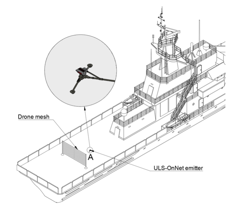
Figure: Landing on ship application
Net recovery systems. ULS-OnNet provides precision guidance for aircraft designed to land in recovery nets, holding an accurate approach vector under challenging conditions.
Tether-based platforms. Precision guidance onto tether systems, supporting reliable recovery for surveillance and monitoring missions.
Ground-based landing. Adaptable to conventional runway landing where high-precision guidance is required.
Maritime platforms. Designed to operate from moving vessels, compensating ship motion through the transmitter level correction system.
System Architecture
flowchart LR
  subgraph GND["Ground / Vessel Installation"]
    TX["ULSDV-ON-TX-G2 Transmitter\n• IR emission 940nm\n• 30° x 30° field\n• Level correction ±20°\n• 20-28V, 30W"]
    PC["Setup PC\n• USB\n• Configuration & diagnostics"]
  end
  subgraph AIR["Fixed-Wing Aircraft"]
    RX["ULSDV-ON-RX-G2 Receiver\n• IR sensor 940nm\n• 60° x 30° FOV\n• Relative position, 20Hz\n• 12-24V, 10W"]
    AP["Autopilot\n• MAVLink\n• CAN (ULS-Blitz)\n• Landing path control"]
  end
  TX -->|"Structured IR field, up to 300m"| RX
  PC -->|"Setup & diagnostics"| TX
  RX -->|"Relative position & status"| AP
The transmitter is the navigation beacon; the receiver is the navigation sensor. All positioning is computed on board from the received optical field, so the aircraft does not depend on a data link with the ground during the approach. Several aircraft can operate simultaneously inside the field of a single transmitter.
System Base Components
Receiver — Onboard Module (ULSDV-ON-RX-G2)
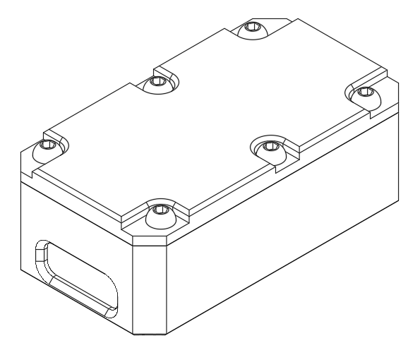
Figure: Onboard receiver (ULSDV-ON-RX-G2)
The onboard infrared receiver is the navigation sensor of the system. It captures the infrared signal from the ground transmitter and converts it into navigation data for the autopilot. Several receivers may be installed on one vehicle where redundant operation is required.
Key functions:
- IR signal reception — detects and decodes the 940 nm infrared navigation signal from the ground transmitter within the 300 m range
- Spatial processing — converts the received optical data into precise position and orientation information relative to the landing zone
- Autopilot interface — transmits processed navigation data to the autopilot over CAN or UART
- Real-time updates — continuous position output at 20 Hz for smooth approach guidance
- System integration — works with MAVLink and with custom autopilot solutions
Transmitter — Ground Module (ULSDV-ON-TX-G2)
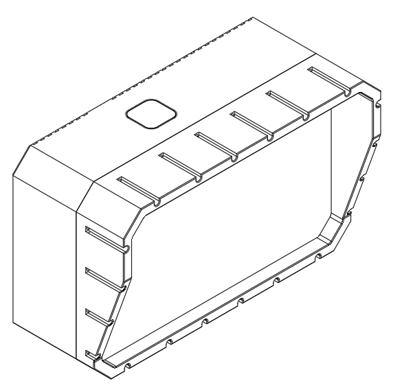
Figure: On-runway portable transmitter, 300 m (ULSDV-ON-TX-G2)
The ground-based infrared transmitter is the primary navigation beacon of the system. It projects a structured infrared field that provides spatial reference information to approaching aircraft within a 300 m operational range. It is mounted on the ground or on a vehicle or vessel.
Key functions:
- IR beacon generation — creates a precise infrared navigation field with 30° horizontal and vertical coverage
- Spatial reference — provides the position and orientation reference that makes accurate landing guidance possible
- Real-time status — transmits system status and diagnostic information to the onboard receiver
- Flexible operation — multiple vehicles can operate in the field of a single transmitter simultaneously
Part Numbering
| Part number | Item | Description |
|---|
| ULSDV-ON-TX-G2 | Transmitter | Ground/vehicle-mounted infrared transmitter, 300 m range |
| ULSDV-ON-RX-G2 | Receiver | Onboard infrared receiver module, 85 g |
Table: ULS-OnNet-G2 Device Part Numbers
The ULSDV-ON prefix identifies devices of the ULS-OnNet family; the -G2 suffix identifies the generation of the device.
Technical Specifications
General Specifications
| Parameter | Specification |
|---|
| Operation range | 300 m |
| Navigation method | Optical (infrared, 940 nm) |
| Radio wave independence | No GNSS or radio wave reliance for the landing solution |
| Optional connectivity | GNSS and radio connectivity available on request |
| Update rate | 20 Hz |
| Start-up time | 2.8 s |
| Landing capability | Nets, tethers, and ground |
Table: General System Specifications
Field of View
| Component | Horizontal | Vertical |
|---|
| Transmitter (emission field) | 30 degrees | 30 degrees |
| Receiver (sensor field) | 60 degrees | 30 degrees |
Table: Field of View Specifications
Accuracy
| Parameter | Specification |
|---|
| Horizontal accuracy | 0.8 degrees |
| Vertical accuracy | 0.8 degrees |
| Resolution (horizontal and vertical) | 0.1 degrees |
| Distance estimation accuracy | 2 m or 20 % of the distance, whichever is greater |
Table: System Accuracy and Resolution
Angular accuracy is the primary specification of the system: the linear position error therefore grows in proportion to the distance from the transmitter, and the guidance becomes progressively tighter as the aircraft closes on the recovery point. Distance estimation is a coarser measurement than the angular solution and is intended to support approach staging, not touchdown geometry.
Power Requirements
| Unit | Supply | Consumption |
|---|
| Ground unit (ULSDV-ON-TX-G2) | 20 – 28 V DC, 3 A (battery or external supply) | 30 W |
| Onboard unit (ULSDV-ON-RX-G2) | 12 – 24 V DC, 1.2 A | 10 W |
Table: Power Supply and Consumption
Communication and Connectivity
| Parameter | Specification |
|---|
| Data connectivity | CAN, RS422, UART |
| Setup interface | USB |
| Communication protocols | MAVLink, ULS-Blitz over CAN; custom protocol solutions on request |
Table: Communication Interfaces and Connectivity Options
Transmitter Level Correction System
| Parameter | Specification |
|---|
| Level correction limit | 20 degrees |
| Level correction accuracy | 0.1 degrees |
Table: Transmitter Level Correction System Capabilities
Environmental Specifications
| Parameter | Range |
|---|
| Operating temperature range | −40 °C to +85 °C |
| IP rating | IP67 (dust-tight, protected against temporary immersion) |
Table: Environmental Operating Conditions and Protection Rating
All ULS-OnNet equipment is sealed to IP67 and is intended for continuous outdoor and shipborne operation without additional weather protection. Qualification test data and certification documentation are available from UAVLAS on request.
Mechanical Specifications
Ground Unit (ULSDV-ON-TX-G2)
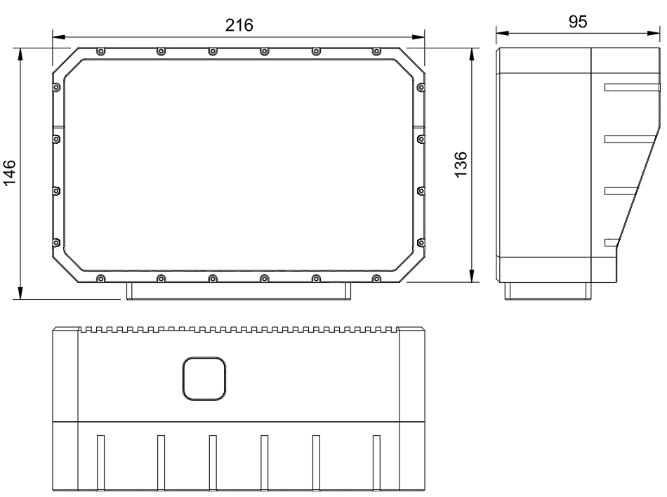
Figure: ULSDV-ON-TX-G2 dimensions
| Parameter | Specification |
|---|
| Dimensions | 213 × 136 × 95 mm |
| Weight | 3200 g |
Table: Transmitter Physical Specifications
Onboard Unit (ULSDV-ON-RX-G2)
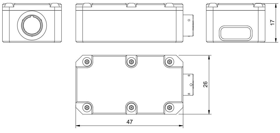
Figure: ULSDV-ON-RX-G2 dimensions
| Parameter | Specification |
|---|
| Dimensions | 47 × 26 × 17 mm |
| Weight | 85 g |
Table: Receiver Physical Specifications
Interface Summary
ULS-OnNet uses an optical link between the ground and the aircraft, and wired interfaces on each side of that link.
- Transmitter to receiver: optical infrared link, 940 nm, up to 300 m
- Transmitter to setup PC: USB, for configuration and diagnostics
- Receiver to autopilot: CAN or UART; RS422 and USB are available on the transmitter side
Transmitter Connector
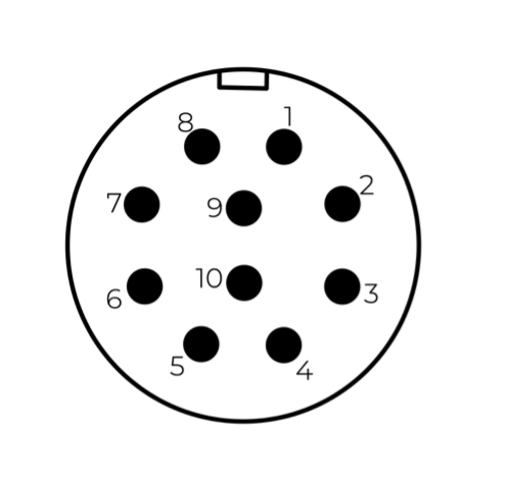
Figure: ULSDV-ON-TX-G2 connector pin numbers
| Pin | Function |
|---|
| 1 | Vin +18 V … +28 V |
| 2 | RS422A |
| 3 | RS422B |
| 4 | RS422Y |
| 5 | RS422Z |
| 6 | CAN-L |
| 7 | CAN-H |
| 8 | USB-D− |
| 9 | USB-D+ |
| 10 | GND |
Table: ULS-OnNet transmitter pinout
Do NOT "hot-plug" the transmitter cable. Apply power to the transmitter only when the connector is mated to the transmitter.
Check the pin numbers on the connector before wiring.
Incorrect wiring, or connection while under voltage, can damage the device and the USB interface of the connected PC.
Receiver Connector

Figure: ULSDV-ON-RX-G2 connector pin numbers
| Pin | Function |
|---|
| 1 | Vin (supply — see Power Requirements) |
| 2 | CAN-H |
| 3 | CAN-L |
| 4 | UART_TX (out) |
| 5 | UART_RX (in) |
| 6 | USB_D− |
| 7 | USB_D+ |
| 8 | GND |
Table: ULS-OnNet receiver pinout
Autopilot Integration
Integration Options
Standard protocol (MAVLink). The widely used open communication protocol for UAVs; integration with MAVLink-compatible autopilots is the simplest path.
CAN protocol (ULS-Blitz messages). Navigation data can be taken directly from the CAN bus using ULS-Blitz messages. See ULSDC-PBDS031025-ULS-Blitz-Types-and-Description.
Custom solution. UAVLAS can supply a custom integration where the autopilot does not support MAVLink or where specific functionality is required.
Data Provided by ULS-OnNet
Relative position. The onboard unit outputs the position of the aircraft relative to the ground transmitter, derived from the infrared navigation field.
System diagnostics. Transmitter level and life status are relayed to the onboard side.
Role of the Autopilot
Aircraft control. The autopilot remains responsible for flying the aircraft, including stability and manoeuvring during the approach.
Landing path calculation. The autopilot uses the relative position from ULS-OnNet to compute and fly a precise path into the net or onto the tether.
Installation
Ground Equipment
The ground segment of ULS-OnNet consists of a single main component and is straightforward to install.
Simplified setup. The transmitter is pointed along the intended landing path direction; no further alignment infrastructure is required.
Typical placement. The transmitter is ideally positioned behind the landing zone — behind the net or tether — for optimal signal geometry during the approach.
Fast start-up. The system becomes operational within 3 seconds of power being applied, which suits rapid deployment.
Levelling Requirements
Why levelling matters. A level transmitter installation maximises the usable radiation angle, and therefore the coverage area of the infrared field.
Level correction system. The built-in level correction system compensates minor mounting errors within a 20° range, at the cost of a slight reduction in the effective viewing angle.
Stabilised platform recommendation. For installation on objects with a high chance of tilting beyond 20° of roll, a stabilised platform is recommended to keep the transmitter level. UAVLAS offers customised solutions for such installations on request.
Onboard Equipment
Mounting. The receiver is mounted with a clear view along the approach direction, so that the transmitter stays inside the 60° × 30° sensor field through the whole approach.
Redundancy. A second receiver may be added and mounted so that the two units cover the approach independently.
Power and data. The receiver is supplied from the aircraft bus (12 – 24 V DC, 10 W) and connects to the autopilot over CAN or UART.
ULS-OnNet-G2 is delivered as a complete precision landing solution containing everything needed for deployment: hardware modules, connectivity accessories, and documentation.
Standard Package Contents
| Component | Quantity | Part number | Description |
|---|
| Transmitter unit | 1 | ULSDV-ON-TX-G2 | Ground-based infrared transmitter, 300 m range |
| Receiver unit | 1 | ULSDV-ON-RX-G2 | Onboard infrared receiver module (85 g) |
| Transmitter cable | 1 | - | 10-pin connector cable for the transmitter |
| Receiver cable | 1 | - | 8-pin connector cable for the receiver |
| USB configuration cable | 2 | - | For system setup and diagnostics |
| Mounting hardware | 1 set | - | Brackets and screws for installation |
| Quick start guide | 1 | - | Initial setup instructions |
| Technical documentation | 1 set | - | Complete system manuals and specifications |
Table: ULS-OnNet-G2 Standard Package Contents
Optional Accessories
| Component | Part number | Description |
|---|
| Secondary receiver | ULSDV-ON-RX-G2 | Additional receiver for redundant operation |
| Extended cable kit | - | Longer cables for specific installation requirements |
| Power supply unit | - | Dedicated power supply for the ground transmitter |
Table: Optional Accessories
Optical Radiation Safety (IR Emission)
The transmitter (ground unit) emits pulsed infrared optical radiation with a centre wavelength of 940nm. The receivers are optical sensors only and do not emit optical radiation.
INFRARED RADIATION IS EMITTED FROM THE TRANSMITTER OPTICAL APERTURES WHENEVER THE UNIT IS POWERED. Do not look into the transmitter emitter apertures at close range. IR emission at 940nm is invisible and does not trigger the blink or aversion reflex, so the eye receives no natural warning of exposure.
Why This Warning Is Given
Radiation at 940nm is outside the visible range. The protective mechanisms that limit exposure to bright visible sources — the blink reflex, pupil constriction, and the instinct to look away — are not triggered by an invisible source. Exposure time is therefore limited only by operator behaviour, which is why the precautions below are given as operating instructions and not left to the operator’s judgement.
The transmitter is a positioning beacon. It is not an illumination product and is not intended to be viewed at any time.
Operating Precautions
- Do not look directly into the transmitter emitter apertures from a distance of less than 1 metre while the unit is powered.
- Treat the transmitter as emitting whenever supply voltage is applied, including when no receiver is present and no positioning data is being transferred.
- Switch emission off before working directly in front of the transmitter. Use the Illumination parameter in ULS-Tools to disable emission, or disconnect supply power.
- Do not view the powered transmitter through binoculars, telescopes, camera lenses, magnifiers, or any other light-collecting instrument. Such optics concentrate the emission and can raise the exposure at the eye by orders of magnitude compared with unaided viewing.
- Do not add, remove, or modify optical elements of the transmitter. Added optics change the emission characteristics and invalidate any photobiological classification of the unit.
- Position the transmitter so that the emission field is directed away from work positions and walkways where personnel stay for extended periods.
- Servicing personnel working inside the emission field at close range should disable emission first rather than rely on viewing distance.
Classification and Applicable Standards
| Item | Value |
|---|
| Emitter type | Incoherent IR LED array (not a laser) |
| Centre wavelength | 940nm |
| Emission mode | Pulsed |
| Applicable standard | IEC 62471 / EN 62471, Photobiological safety of lamps and lamp systems |
| Classification distance | 200mm (non-GLS source, per IEC 62471) |
| Risk group | TBD — to be entered from the IEC 62471 assessment report |
| Hazard distance | TBD — to be entered from the IEC 62471 assessment report |
Table: Optical Radiation Safety Data
The transmitter uses light emitting diodes, not laser emitters. LED sources are assessed under IEC 62471; the laser product standard IEC 60825-1 does not apply to this product.
For a 940nm source the applicable exposure limits are the retinal thermal hazard (380nm to 1400nm), the retinal thermal hazard for a weak visual stimulus (780nm to 1400nm, which applies specifically to sources that give no visual cue), and the infrared hazard to the cornea and lens (780nm to 3000nm). The corneal and lens limits are intended for chronic exposures longer than 1000s at a daily averaged irradiance of 100 W/m² or more.
Organisations operating this equipment within the European Union are additionally subject to Directive 2006/25/EC on the exposure of workers to artificial optical radiation, which requires the employer to assess worker exposure against the exposure limit values given in Annex I of that directive. UAVLAS provides the emission data needed for that assessment on request.
Compliance and Standards
- RoHS compliant
- Document classification and release control as defined in the document metadata
- Product-specific compliance statements to be finalised for release
Use the part numbering and packaging sections to identify system variants, subassemblies, and accessories. Communication protocol selection is agreed per installation; optional GNSS and radio connectivity can be supplied for preliminary calculation of the landing slope.
Change Control
All changes to this document must be reviewed and approved by the relevant technical leads and stakeholders
References
- ULSDC-PBDS031025-ULS-Blitz-Types-and-Description