ULS-XSpot Documentation
Precision positioning for tethered drones, with a tether-compatible transmitter.
Application
ULS-XSpot is built for tethered drone operations: the transmitter has a
centre through hole, so the tether cable passes through the unit without
obstructing the optical field. It suits stationary or slow-moving tethered
drones that need precise positioning over the ground station during flight
and landing, over a working distance of up to 50 m.
ULS-XSpot-G3 shares the generation 3 platform with ULS-Heli-G3, including
the dual receiver architecture for redundancy and MRX yaw estimation.
Documents
Each page is generated from the source of the controlled PDF; the numbered PDF can be downloaded from the document portal.
1 - ULS-XSpot Datasheet
Specifications, performance, dimensions and pinouts of ULS-XSpot — precision positioning for tethered drones, with a tether-compatible transmitter.
ULSDC-PBDS231125 · version 1.0.1 · issued November 23, 2025
The numbered PDF is the controlled copy: download it from the portal.
Introduction
Purpose
The purpose of this datasheet is to provide comprehensive technical information about the ULS-XSpot System family, specifically designed for tethered drone operations. This includes specifications, performance characteristics, and detailed descriptions of system components, such as the tether-compatible transmitter and receivers. By outlining the interfaces between these components, the datasheet aims to facilitate seamless integration and operation for system engineers, integrators, and developers working with tethered drone systems.
Scope
This document is intended for use by system engineers, integrators, and developers working with ULS-XSpot systems in tethered drone applications. It provides detailed information on the system, with special emphasis on tethered drone operation requirements and the 50-meter working range.
Key Differences from ULS-Heli-G2
The ULS-XSpot system is optimized for tethered drone operations and features the following key differences:
- Tethered Design: Transmitter features a center hole for tether cable passage, enabling integration with tethered drone power and data systems
- Simplified Optics: Standard IR optical link without DACS technology, over the same 50-meter working distance as ULS-Heli-G2
- Application Focus: Specifically designed for stationary or slow-moving tethered drone operations with continuous power availability
System Base Components
Transmitter (Ground Unit - Tethered Design)
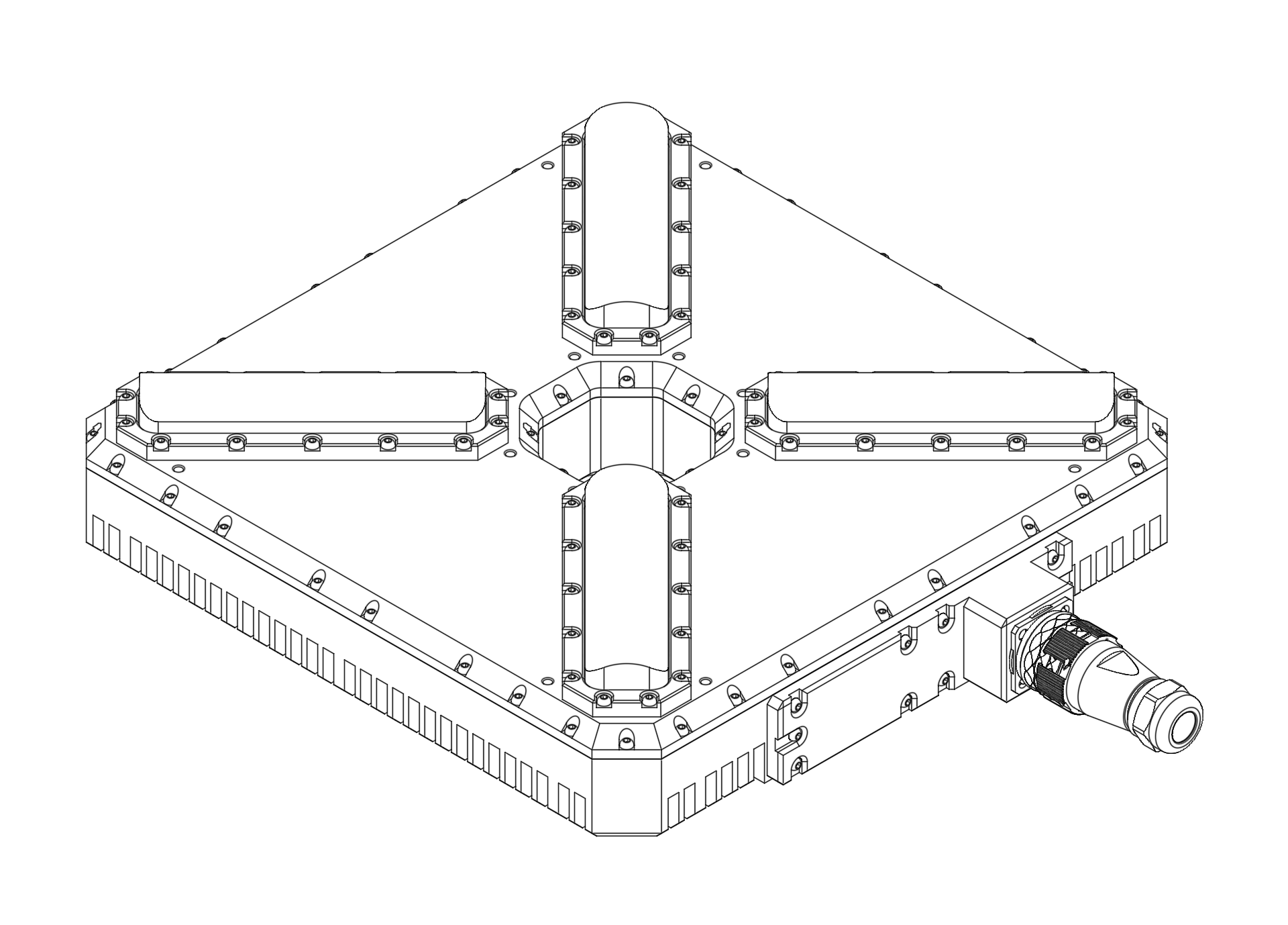
Figure: ULS-XSpot Transmitter with Center Tether Hole
The ULS-XSpot transmitter is specifically designed for tethered drone systems. It features a center hole for tether passage, allowing the drone’s power and data cable to pass through while maintaining optical positioning capabilities. The transmitter is placed on the ground (platform, moving object) and emits a signal in the Infrared range, serving as a positioning beacon for tethered drone landing and station-keeping.
The primary function of the transmitter is to continuously send out a coded signal that can be detected and interpreted by the receiver unit onboard the tethered copter. This signal contains critical information needed for the operation of the system, such as positional data and status. The tethered design allows for extended flight duration while maintaining precision positioning.
Key Features:
- Center hole for tether cable passage (integrated tether management)
- Working range: 50 meters working distance
- Optimized for tethered drone operations
- Continuous power available via tether connection
Receiver (Onboard Unit)
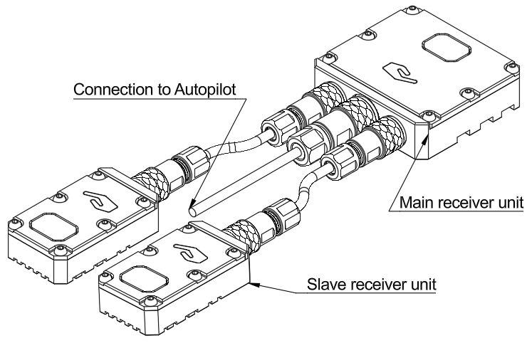
Figure: ULS-XSpot Receiver
The receiver is a device that is placed on board the tethered aircraft.
The receiver decodes the IR signal to derive flight information such as positional coordinates, real-time transmitter status updates, and positioning guidance. It interprets the data to navigate accurately and ensure the drone maintains its position relative to the ground station. It provides feedback to autopilot systems, such as Ardupilot and PX4, to adjust the flight parameters as needed for optimal station-keeping, landing, or hovering operations while connected to the tether.
Key Features:
- Compatible with tethered drone configurations
- Real-time position feedback for station-keeping
- Seamless integration with tether management systems
Part Numbering
| Part Number | Description |
|---|
| ULS-XSPOT | System set with 3 receivers for tethered drone systems. |
| ULSDV-XS-TX | Transmitter unit with center tether hole. |
| ULSDV-XS-RXM | Master receiver unit. |
| ULSDV-XS-RXS | Slave receiver unit. |
| SA610/P4IB | 4 Pin Connector for receiver. Manufacturer Weipu. |
| SA810/P8IIB | 8 Pin Connector for receiver. Manufacturer Weipu. |
| SA1610/P10IIB-1 | 10 Pin Connector for transmitter. Manufacturer Weipu. |
Table: Part Numbering
System Specification
| Parameter | Value |
|---|
| Distance range m.: | 50.0 |
| Working angle (deg): | 60 |
| Data update frequency (Hz): | 20 |
| Technology: | Standard IR Optical (No DACS) |
Table: Common Specification
| Parameter | Value |
|---|
| Field of view (deg): | 90 |
| Dimensions mm : | 46x26x12 |
| Weight g.: | 40 |
| Power Consumption (W): | 3 |
| Voltage supply (V): | 5 |
| Interfaces: | USB, CAN, UART |
Table: Receiver (Slave) Specifications
| Parameter | Value |
|---|
| Field of view (deg): | 90 |
| Dimensions mm : | 50x50x14 |
| Weight g. : | 60 |
| Power Consumption (W): | 3 |
| Voltage supply (V): | 5 |
| Interfaces: | USB, CAN, UART |
Table: Receiver (Master) Specifications
| Parameter | Value |
|---|
| Field of emitting (deg): | 35 |
| Dimensions mm. : | 290x215x48 |
| Weight g.: | 4100 |
| Power Consumption (W): | 10 |
| Voltage supply (V): | 22.0-26.0 |
| Interfaces : | USB, CAN, UART |
| Special Features: | Center hole for tether passage |
Table: Transmitter (Ground) Specifications - Tethered Design
Transmitter Pinout
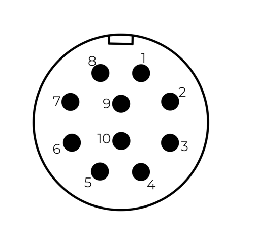
| Pin | Function |
|---|
| 1 | Vin +18V – +28V |
| 2 | RS422A |
| 3 | RS422B |
| 4 | RS422Y |
| 5 | RS422Z |
| 6 | CAN-L |
| 7 | CAN-H |
| 8 | USB-D- |
| 9 | USB-D+ |
| 10 | GND |
Table: Transmitter 10 Pin Connector Pinout
Please DO NOT "HOT-PLUG" Transmitter cable. Apply power on transmitter only when connector connected to transmitter.
Please check pin numbers on connector.
Incorrect wiring or connection under voltage can damage the device and USB interface of connected PC !
Special Note for ULS-XSpot: The transmitter includes a center hole for tether cable passage. Ensure tether cable routing does not obstruct the IR emission pattern.
Receiver Pinout
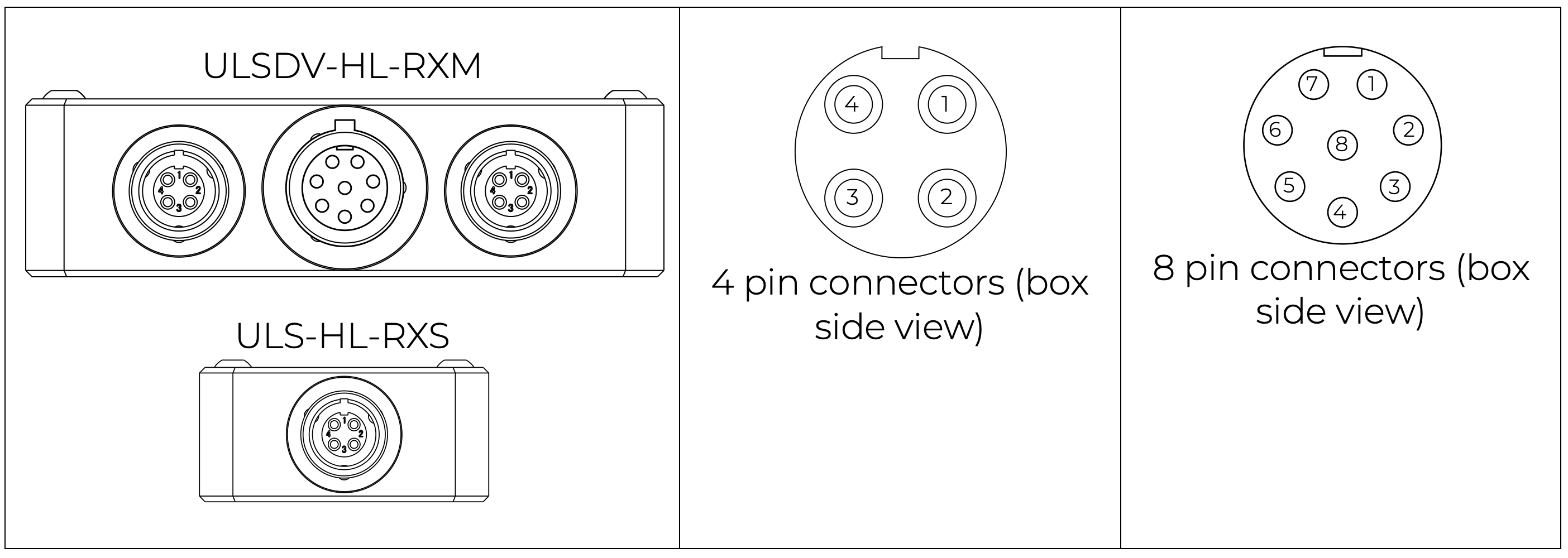
| Pin | Function |
|---|
| 1 | Vin (+5V) |
| 2 | CANH |
| 3 | CANL |
| 4 | GND |
Table: 4 Pin Connector Pinout
| Pin | Function |
|---|
| 1 | Vin (+5V) |
| 2 | CANH |
| 3 | CANL |
| 4 | UART_TX (OUT) |
| 5 | UART_RX(IN) |
| 6 | USB_D- |
| 7 | USB_D+ |
| 8 | GND |
Table: 8 Pin Connector Pinout
Mechanical Dimensions
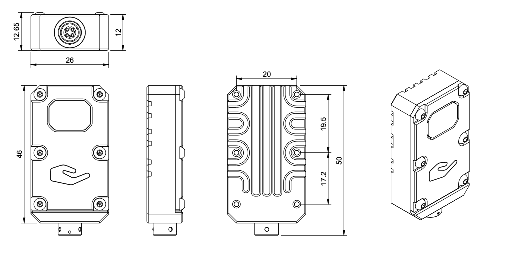
Figure: Slave Receiver Mechanical Dimensions
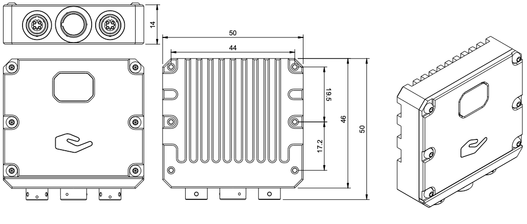
Figure: Master Receiver Mechanical Dimensions
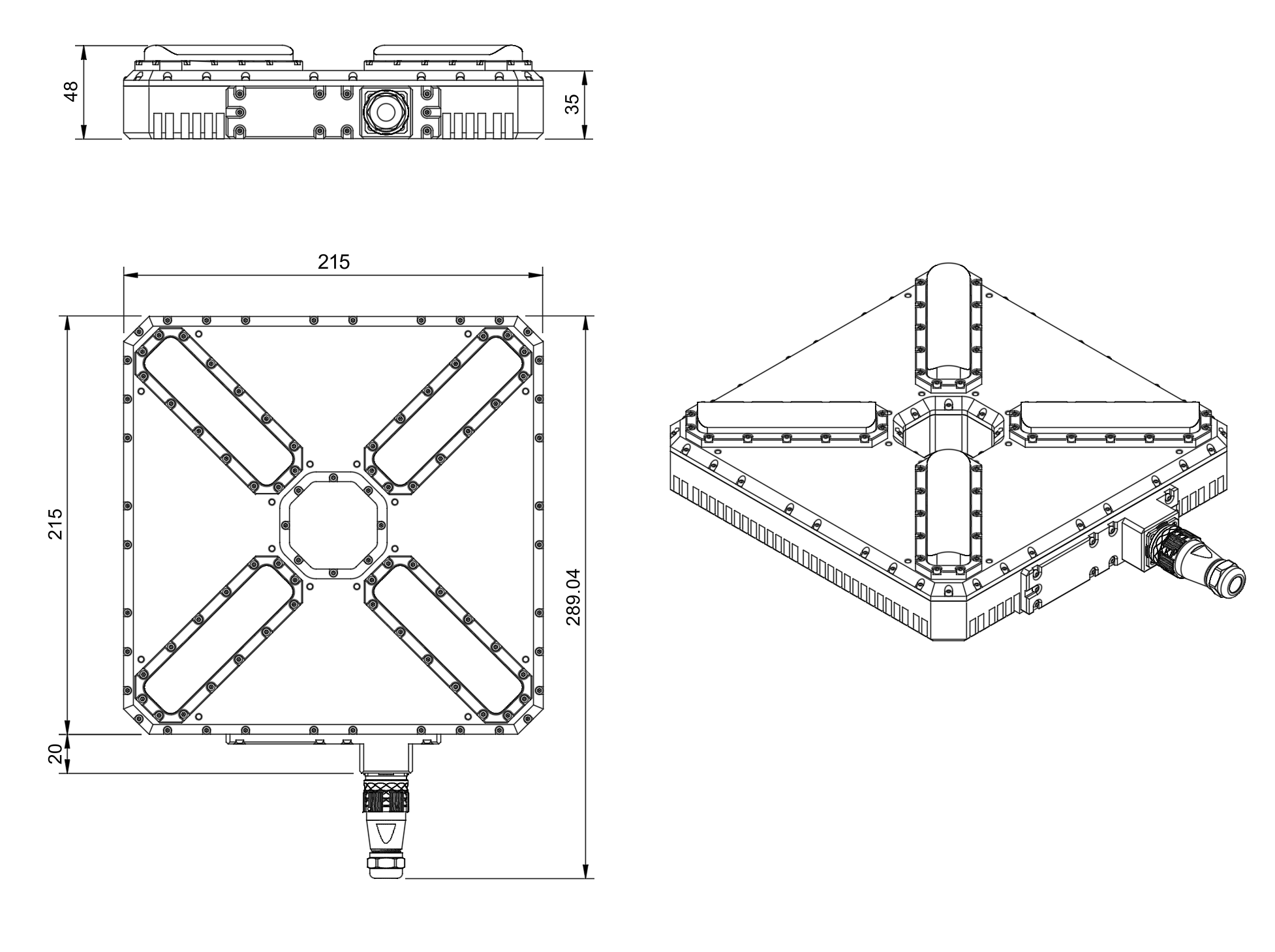
Figure: Transmitter Mechanical Dimensions with Center Tether Hole
Note: The transmitter features a center hole designed for tether cable passage, enabling integration with tethered drone power and data systems.
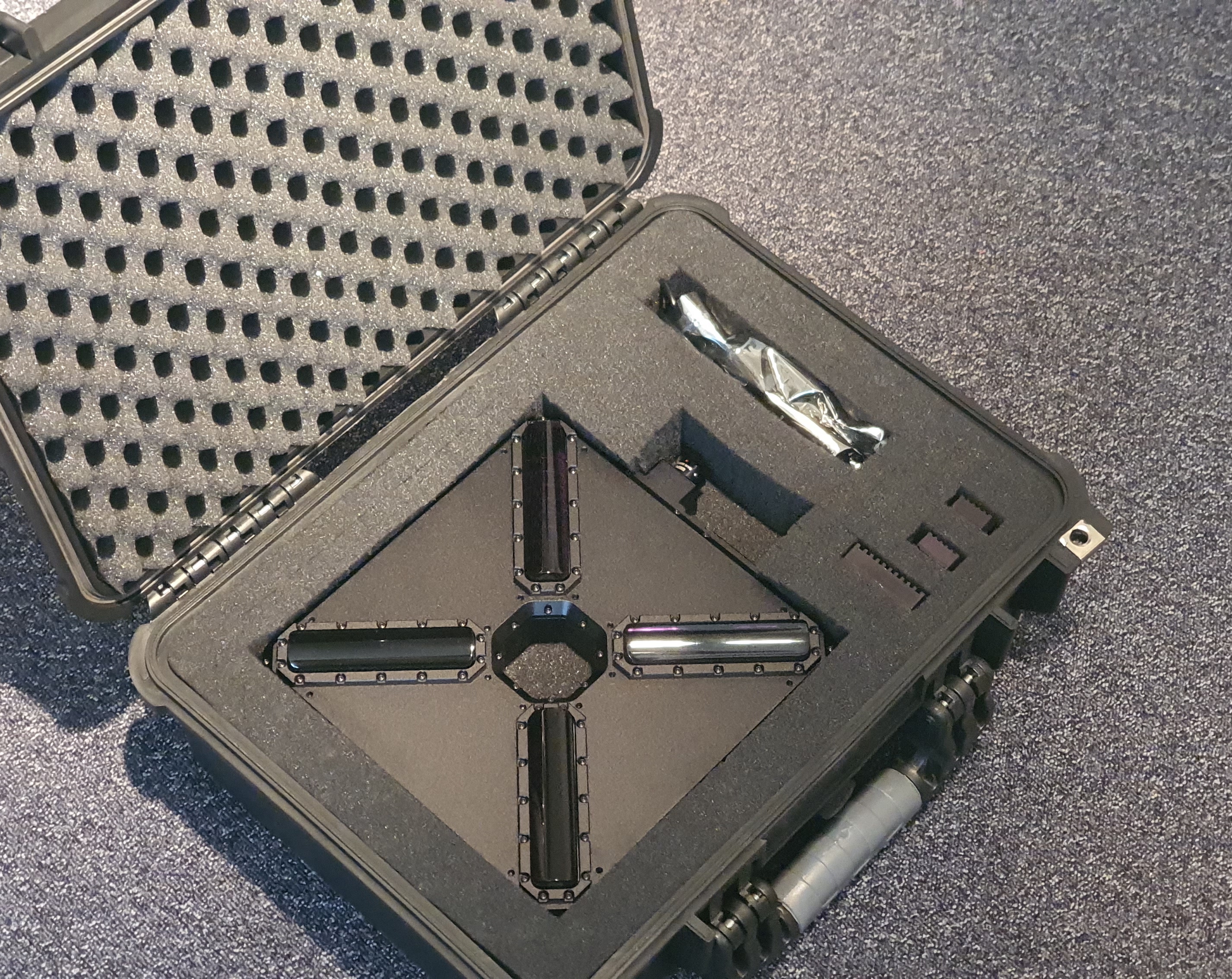
Figure: ULS-XSpot System Package
The ULS-XSpot system is packaged in a protective hard case designed for field deployment in tethered drone operations.
Package Contents
- 1x Transmitter unit (with center tether hole)
- 1x Master receiver unit
- 2x Slave receiver units
- Connection cables
- Mounting hardware
- Quick start guide
- USB configuration cable
Package Specifications
| Parameter | Value |
|---|
| Case Type | Hard protective case |
| Dimensions (LxWxH) | Approx. 450 x 350 x 200 mm |
| Weight (with equipment) | Approx. 6 kg |
Table: Package Specifications
Environmental Conditions - Industrial Grade
Equipment is designed to operate reliably in demanding environmental conditions typical of aerospace, industrial automation, and outdoor applications.
Operating Temperature Range
- Standard operating range: -20°C to +55°C
- Covers most industrial and outdoor applications
- Reliable performance across temperature extremes
- No performance degradation within specified range
Humidity Tolerance
- Relative humidity: Up to 70% (non-condensing)
- Protected against moisture in typical operating conditions
- Suitable for outdoor and semi-protected installations
- Condensation prevention through sealed design
Ingress Protection
- IP67 rated (Dust tight and water immersion resistant)
- 6 - Complete protection against dust ingress
- 7 - Protected against temporary immersion in water (up to 1 meter depth for 30 minutes)
- Suitable for harsh industrial environments
- Protected against rain, splashing, and temporary submersion
- Dust-tight sealing for contaminated environments
Storage Conditions
- Storage temperature: -40°C to +70°C
- Relative humidity: Up to 95% (non-condensing)
- Long-term storage in industrial facilities
Operational Environment Standards
- Designed to meet industrial equipment requirements
- Suitable for UAV/drone applications
- Outdoor installation capable
- Protected against:
- Dust and particulate matter
- Water spray and rain
- Temporary water immersion
- Temperature fluctuations
- High humidity
Tethered Operation Guidelines
System Integration
The ULS-XSpot system is specifically designed to work with tethered drone platforms. Key integration considerations include:
- Tether Routing: Route the tether cable through the center hole of the transmitter
- Clearance: Maintain minimum 10cm clearance around transmitter for optimal IR propagation
- Cable Management: Secure tether to prevent interference with optical path
- Ground Station Setup: Position transmitter at the tether connection point for optimal positioning reference
Advantages for Tethered Drones
- Extended Flight Time: Continuous power via tether enables unlimited operation duration
- Stable Reference: Tether provides additional stability reference for position control
- Simplified Design: Center hole design integrates cleanly with tether management systems
- Enhanced Safety: Physical tether connection adds redundancy to positioning system
- Weather Resilience: Extended operation capability in various weather conditions with continuous power
Change Control
All changes to this document must be reviewed and approved by the relevant technical leads and stakeholders
2 - ULS-XSpot Interface Control Document
Electrical, mechanical and communication interfaces of ULS-XSpot — precision positioning for tethered drones, with a tether-compatible transmitter.
ULSDC-PBICD231125 · version 1.0.2 · issued November 23, 2025
The numbered PDF is the controlled copy: download it from the portal.
Introduction
Purpose
This document outlines the interfaces between the ULS-XSpot system components, including the tether-compatible transmitter, receiver, and autopilot systems (Ardupilot, PX4, and similar). The ULS-XSpot is specifically designed for tethered drone operations with a 50-meter working range.
Scope
This document is intended for use by system engineers, integrators, and developers working with ULS-XSpot systems in tethered drone applications. It provides detailed information on the interfaces between the system components, ensuring seamless integration and operation with tether management systems.
Key Features for Tethered Operations
- Tether-Compatible Design: Center hole in transmitter for cable passage
- Working Range: 50-meter working distance
- Standard IR Optical: No DACS technology required
- Continuous Operation: Designed for 24/7 operation with tethered power
System Components
Transmitter (Ground Unit - Tethered Design)
Figure: ULS-XSpot Transmitter with Center Tether Hole
The ULS-XSpot transmitter is specifically designed for tethered drone systems. It features a center hole for tether passage, allowing the drone’s power and data cable to pass through while maintaining optical positioning capabilities. The transmitter is placed on the ground (platform, moving object) and emits a signal in the Infrared range, serving as a positioning beacon for tethered drone landing and station-keeping.
The primary function of the transmitter is to continuously send out a coded signal that can be detected and interpreted by the receiver unit onboard the tethered copter. This signal contains critical information needed for the operation of the system, such as positional data and status. The tethered design allows for extended flight duration while maintaining precision positioning.
Key Features:
- Center hole for tether cable passage (integrated tether management)
- Working range: 50 meters working distance
- Optimized for tethered drone operations
- Continuous power available via tether connection
Receiver (Onboard Unit)
Figure: ULS-XSpot Receiver
The receiver is a device that is placed on board the tethered aircraft.
The receiver decodes the IR signal to derive flight information such as positional coordinates, real-time transmitter status updates, and positioning guidance. It interprets the data to navigate accurately and ensure the drone maintains its position relative to the ground station. It provides feedback to autopilot systems, such as Ardupilot and PX4, to adjust the flight parameters as needed for optimal station-keeping, landing, or hovering operations while connected to the tether.
Key Features:
- Compatible with tethered drone configurations
- Real-time position feedback for station-keeping
- Seamless integration with tether management systems
Interface Overview
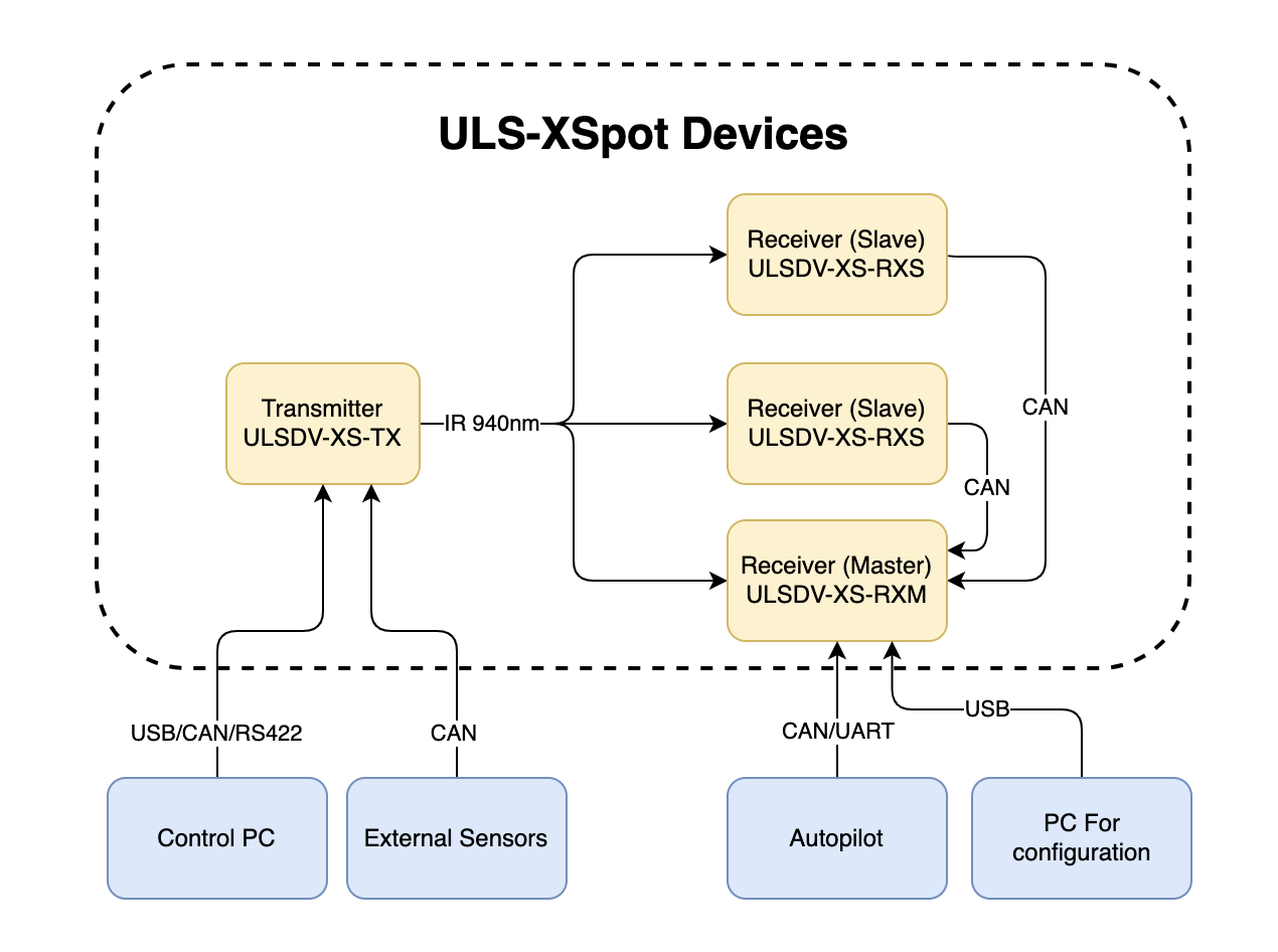
Figure: ULS-XSpot System Interfaces Overview
Note: The ULS-XSpot uses the same interface architecture as ULS-Heli-G2, with the addition of tether-compatible mechanical design.
Transmitter to Control PC Interface (External Sensors)
The transmitter can be connected to a control PC or external equipment for configuration, status monitoring, and data exchange.
Data Types
- Status information
- Control signals
- Transmitter configuration
- External IMU/COMPASS data
Connection Types
- CAN Bus - For network communication
- USB - For configuration and firmware updates
- RS422 - For serial communication with external sensors
Transmitter Pinout
| Pin | Function |
|---|
| 1 | Vin +18V – +28V |
| 2 | RS422A |
| 3 | RS422B |
| 4 | RS422Y |
| 5 | RS422Z |
| 6 | CAN-L |
| 7 | CAN-H |
| 8 | USB-D- |
| 9 | USB-D+ |
| 10 | GND |
Table: Transmitter 10 Pin Connector Pinout
Please DO NOT "HOT-PLUG" Transmitter cable. Apply power on transmitter only when connector connected to transmitter.
Please check pin numbers on connector.
Incorrect wiring or connection under voltage can damage the device and USB interface of connected PC !
Tethered System Note: When routing tether cable through the center hole, ensure the cable does not interfere with connector access or IR emission pattern.
Transmitter to Receiver Interface
The transmitter and receiver use an optical interface to exchange data. Transmission uses IR emission at 940 nanometers. Data transmission is only in the direction from the transmitter to the receiver.
| Parameter | ULS-XSpot | ULS-Heli-G2 | Notes |
|---|
| Maximum Range | 50m | 50m | Same range |
| Working Angle | 60° | 60° | Emission cone |
| Technology | Standard IR | IR + DACS | Simplified for tethered use |
| Update Rate | 20Hz | 20Hz | Same performance |
Table: Optical Interface Comparison
Data Types
- Position encoded
- Status encoded data (Transmitter orientation and instructions)
Connection Type
- Optical IR 940nm - Infrared optical link
Tethered Operation: The 50-meter range covers typical tethered drone operating heights. Tether provides stable reference, reducing positioning complexity compared to free-flight applications.
Receiver to Autopilot and Receiver to PC Interfaces
Data Types
- MAVLink messages
- ULS-Blitz frames
- ASCII protocol
Connection Types
- UART - Serial communication with autopilot
- CAN - Network communication
- USB - Direct PC connection
Receiver Pinout
| Pin | Function |
|---|
| 1 | Vin (+5V) |
| 2 | CANH |
| 3 | CANL |
| 4 | GND |
Table: 4 Pin Connector Pinout
| Pin | Function |
|---|
| 1 | Vin (+5V) |
| 2 | CANH |
| 3 | CANL |
| 4 | UART_TX (OUT) |
| 5 | UART_RX(IN) |
| 6 | USB_D- |
| 7 | USB_D+ |
| 8 | GND |
Table: 8 Pin Connector Pinout
Powering Interfaces
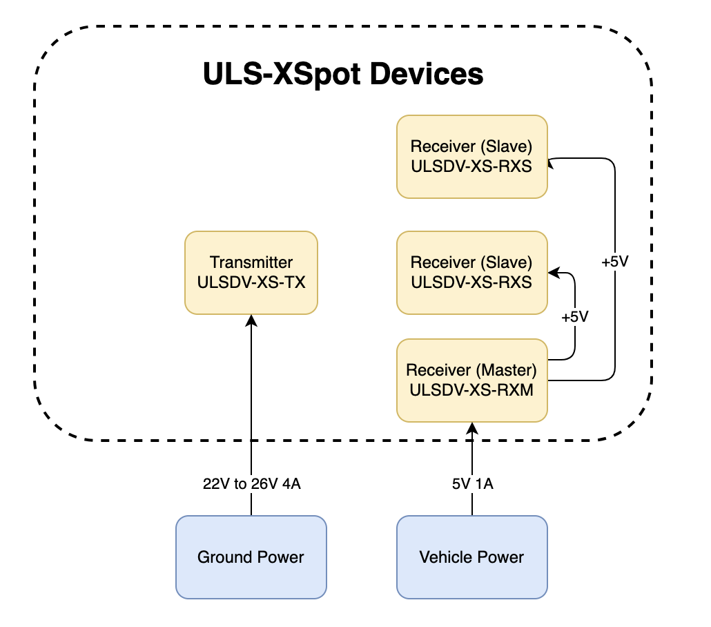
Figure: Power Distribution and Connections
Transmitter Electrical Characteristics
| Parameter | Value | Unit | Notes |
|---|
| Supply Voltage | 22.0 - 26.0 | V | Nominal 24V |
| Supply Current | 4 | A | Peak |
| Power Consumption | 18.1 | W | Typical |
Table: Transmitter Electrical Specifications
Tethered System Power: Transmitter can be continuously powered from ground station power supply. Consider tether voltage drop when sizing power system for long tether runs.
Receiver Electrical Characteristics
| Parameter | Value | Unit | Notes |
|---|
| Supply Voltage | 5.0 | V | From flight controller or tether |
| Supply Current | 1 | A | Peak |
| Power Consumption | 3 | W | Typical |
Table: Receiver Electrical Specifications
Tethered Power Option: Receiver can be powered from flight controller or directly from tether power distribution system.
Functional Diagram
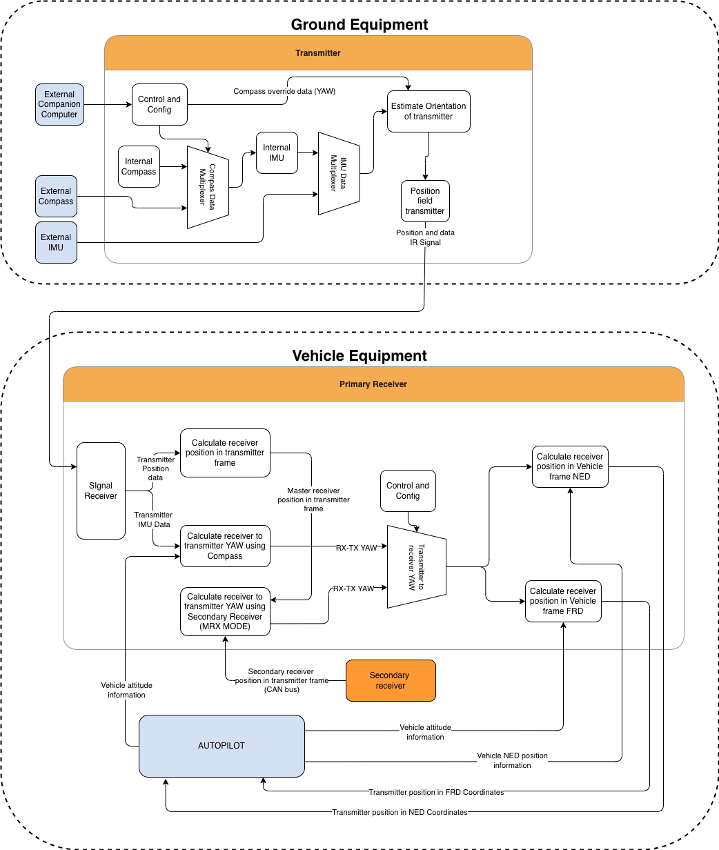
Figure: Functional description of the system
Functional Interfaces
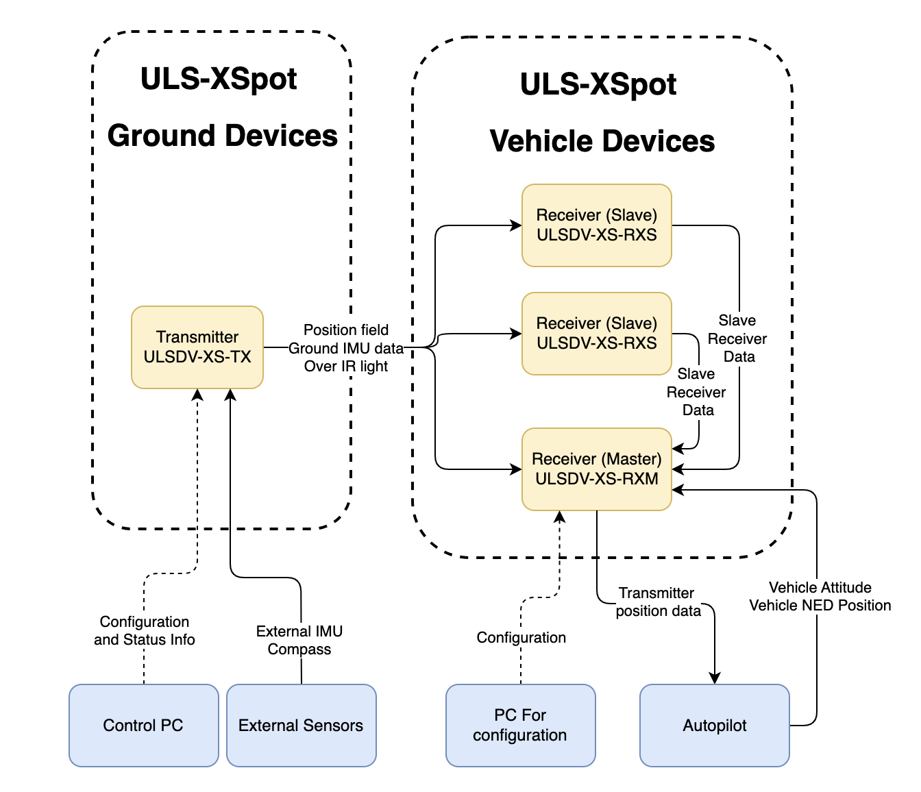
Figure: Data Flow and Functional Interfaces
Data Exchange
The ULS-XSpot system implements several data exchange mechanisms optimized for tethered operations:
Control PC Functions:
- Configure and view status of transmitter
- Set configuration of receivers
- Send control signals (On/off, compass override information)
- Monitor tethered operation parameters
External Equipment:
- External IMU/Compass equipment can be used to override internal IMU/compass information
- Tether management system integration for position reference
Receiver Functions:
- Accept data from transmitter over IR signal (position field information and ground unit IMU data)
- Accept NED and Attitude information from autopilot to convert coordinate system
- Multiple receivers can communicate to calculate vehicle orientation (YAW)
- Send position offset data to autopilot
- Support for tethered flight modes and station-keeping
Tethered System Integration
Ground Station Interface:
- Power distribution to transmitter via ground power supply
- Data connection for configuration and monitoring
- Tether management system coordination
Aircraft Interface:
- Position data from ULS-XSpot receiver to autopilot
- Tether tension and status monitoring (external system)
- Coordinated flight control for tethered operations
Mechanical Interfaces
Figure: Slave Receiver Mechanical Dimensions
Figure: Master Receiver Mechanical Dimensions
Figure: Transmitter Mechanical Dimensions with Center Tether Hole
Note: The transmitter features a center hole designed for tether cable passage, enabling integration with tethered drone power and data systems.
Transmitter Mounting with Tether
The transmitter features a center hole for tether passage. Key mounting considerations:
- Use 16 mounting holes to secure transmitter to platform
- Route tether cable through center hole before mounting
- Ensure tether has adequate strain relief above and below transmitter
- Maintain 10cm minimum clearance around transmitter for IR emission
- Verify tether routing does not obstruct 60° emission cone
Receiver Mounting
Both master and slave receivers have mounting provisions for secure installation on tethered aircraft. 3D models of the receivers can be provided upon request.
Tethered Aircraft Considerations:
- Position receivers to avoid tether shadow/obstruction
- Consider tether dynamics in receiver placement
- Maintain clear line-of-sight to ground transmitter
Communication Protocols
Overview
The protocol used by devices for configuration is proprietary and is described in other documents. However, the protocol implements the possibility of transmitting messages (Blitz messages) that can be used by the user to control the device and obtain information. These messages are universal, and the format describes the data that is transmitted by various devices in our system connected to a single network.
Use CMD=6 to send Blitz messages.
In this document, the CAN protocol is specified. RS485 is used to implement custom protocols that can be defined in the future.
flowchart LR
  A[Sender Device] --> B[GLOBAL]
  B --> C[CMD = 6]
  C --> D[ID]
  D --> E[dsn_lid]
  E --> F[msg_id]
  F --> G[Blitz Payload data <= 8 bytes]
  G --> H[Receiver Device]
The CAN protocol uses the following frame structure:
| Field | Description |
|---|
| GLOBAL | Flag used to send packets over several local networks |
| CMD | Command field (Use CMD=6 to send Blitz messages) |
| ID | Packet sender ID (local id src_lid for local packets and device id for global packets src_did) |
| dsn_lid | Destination local ID address |
| msg_id | Message ID used to identify Blitz packet types |
Table: CAN Protocol Frame Fields
Status Bit Definitions
Most messages include a status byte with the following bit definitions:
| Bit | Flag | Description |
|---|
| 0 | ULS_STATUS_RX_CARRIER_OK | IR signal detected |
| 1 | ULS_STATUS_RX_SQ_OK | Signal quality OK |
| 2 | ULS_STATUS_RX_POS_OK | Position estimated |
| 3 | ULS_STATUS_RX_VEL_OK | Velocity estimated |
| 4 | ULS_STATUS_RX_GU_IMU_OK | Ground Unit IMU OK |
| 5 | ULS_STATUS_RX_MRX_OK | MRX message received (secondary receiver) |
| 6 | ULS_STATUS_RX_MRXDATA_OK | MRX Yaw and Distance calculated OK |
Table: Status Bit Definitions
Common Data Structure
Blitz Common Data Structure
Structure: __blitz_common_data_struct
| Field | Type | Description |
|---|
src_lid | uint8_t | Source logical ID |
msg_id | uint16_t | Message ID (see message types below) |
data | union | Message-specific data (8 bytes max) |
Table: Blitz Common Data Structure
The union contains all possible message structures:
xcg1_rx_raw_measurmetrx_raw_measurmetrx_pos_in_tx_framerx_mrxrx_dacs
Usage: Universal container for all ULS Blitz message types.
Implementation Notes
- Packed Structures: All structures use
__attribute__((packed)) to ensure no padding bytes are added by the compiler. - Endianness: The protocol assumes little-endian byte order for multi-byte fields.
- Angular Precision: Angular measurements use 16-bit signed integers with specific scaling factors for different ranges.
- Distance Units: Distance measurements may use different units (cm, 10cm increments) depending on the message type.
Message Types
XCG1 Raw Measurement (0x0010)
Message ID: ULS_BLITZ_MSG_ID_XCG1_RX_RAW_MEASURMENT (0x0010)
Structure: __uls_blitz_xcg1_rx_raw_measurmet
| Field | Type | Description |
|---|
status | uint8_t | Status bits (see Status Bit Definitions above) |
d | uint8_t | Distance in 10 cm increments |
aX | int16_t | Angular information X-axis, proportional [-30000 = -30°, +30000 = +30°] |
aY | int16_t | Angular information Y-axis, proportional [-30000 = -30°, +30000 = +30°] |
oF | int8_t | Sensor offset Forward in cm |
oR | int8_t | Sensor offset Right in cm |
Table: XCG1 Raw Measurement Message Format
Purpose: Legacy raw measurement data for XCG1 systems with limited angular range.
Raw Measurement (0x0011)
Message ID: ULS_BLITZ_MSG_ID_RX_RAW_MEASURMENT (0x0011)
Structure: __uls_blitz_msg_rx_raw_measurmet
| Field | Type | Description |
|---|
status | uint8_t | Status bits (see Status Bit Definitions above) |
counter | uint8_t | Message counter for tracking |
aX | int16_t | Angular information X-axis [-180° to +180°] |
aY | int16_t | Angular information Y-axis [-180° to +180°] |
distance | uint16_t | Distance measurement |
Table: Raw Measurement Message Format
Angular Conversion Formula:
degrees = (value_int16 * 180.0f) / 32767.0f
Purpose: Standard raw measurement data with full angular range.
Position in TX Frame (0x0012)
Message ID: ULS_BLITZ_MSG_ID_RX_POS_IN_TX_FRAME (0x0012)
Structure: __uls_blitz_msg_rx_pos_in_tx_frame
| Field | Type | Description |
|---|
status | uint8_t | Status bits (see Status Bit Definitions above) |
counter | uint8_t | Message counter for tracking |
posX | int16_t | Position X-coordinate in transmitter frame (cm) |
posY | int16_t | Position Y-coordinate in transmitter frame (cm) |
posZ | int16_t | Position Z-coordinate in transmitter frame (cm) |
Table: Position in TX Frame Message Format
Purpose: 3D position data relative to the transmitter coordinate system.
Message ID: ULS_BLITZ_MSG_ID_RX_MRX (0x0013)
Structure: __uls_blitz_msg_rx_mrx
| Field | Type | Description |
|---|
status | uint8_t | Status bits (see Status Bit Definitions above) |
counter | uint8_t | Message counter for tracking |
yaw | int16_t | Yaw angle [-180° to +180°] |
distance | uint16_t | Distance measurement in cm |
Table: MRX Information Message Format
Purpose: Multi-receiver (MRX) information for secondary receiver data.
Message ID: ULS_BLITZ_MSG_ID_RX_DACS (0x0014)
Structure: __uls_blitz_msg_rx_dacs
| Field | Type | Description |
|---|
status | uint8_t | Status bits (see Status Bit Definitions above) |
counter | uint8_t | Message counter for tracking |
yaw | int16_t | Yaw angle [-180° to +180°] |
distance | uint16_t | Distance measurement |
yawContinuous | int16_t | Continuous yaw angle ±32768° |
Table: DACS Information Message Format
Purpose: DACS (Distance and Azimuth Correction System) data with continuous yaw tracking. Available on VTOL systems only.
Ground IMU Measurement (0x0020)
Message ID: ULS_BLITZ_MSG_ID_GIMU_MEASUREMENT (0x0020)
Structure: __uls_blitz_msg_gimu_data
| Field | Type | Description |
|---|
status | uint8_t | Status bits (see Status Bit Definitions above) |
counter | uint8_t | Message counter for tracking |
roll | int16_t | Roll angle [-180° to +180°] |
pitch | int16_t | Pitch angle [-180° to +180°] |
yaw | int16_t | Yaw angle [-180° to +180°] |
Table: Ground IMU Measurement Message Format
Angular Conversion Formula:
degrees = (value_int16 * 180.0f) / 32767.0f
Purpose: Ground unit IMU (Inertial Measurement Unit) orientation data.
IMU Override (0x0030)
Message ID: ULS_BLITZ_MSG_ID_XX_TXC_IMU_OVERRIDE (0x0030)
Structure: __uls_blitz_msg_xx_txc_imu_override
| Field | Type | Description |
|---|
control | uint8_t | Control bits (see Control Bits below) |
counter | uint8_t | Message counter for tracking |
roll | int16_t | Override roll angle [-180° to +180°] |
pitch | int16_t | Override pitch angle [-180° to +180°] |
yaw | int16_t | Override yaw angle [-180° to +180°] |
Table: IMU Override Message Format
Control Bits:
| Bit | Description |
|---|
| 0 | SET Roll - Enable roll angle override |
| 1 | SET Pitch - Enable pitch angle override |
| 2 | SET Yaw - Enable yaw angle override |
| 3-7 | Reserved |
Table: IMU Override Control Bits
Angular Conversion Formula:
degrees = (value_int16 * 180.0f) / 32767.0f
Purpose: Override IMU data on ground unit for external orientation control.
Magnetometer Override (0x0031)
Message ID: ULS_BLITZ_MSG_ID_XX_TXC_MAG_OVERRIDE (0x0031)
Structure: __uls_blitz_msg_xx_txc_mag_override
| Field | Type | Description |
|---|
control | uint8_t | Control bits (see Control Bits below) |
counter | uint8_t | Message counter for tracking |
mx | int16_t | Magnetic field X-component |
my | int16_t | Magnetic field Y-component |
mz | int16_t | Magnetic field Z-component |
Table: Magnetometer Override Message Format
Control Bits:
| Bit | Description |
|---|
| 0 | SET override - Enable magnetometer override |
| 1-7 | Reserved |
Table: Magnetometer Override Control Bits
Magnetic Field Conversion Formula:
mag_value = (value_int16 * 1.0f) / 32767.0f
Purpose: Override magnetometer data on ground unit for external compass control.
Tethered System Note: CAN bus protocol can be extended over tether for ground station integration if required.
Environmental Conditions - Industrial Grade
Equipment is designed to operate reliably in demanding environmental conditions typical of aerospace, industrial automation, and outdoor applications.
Operating Temperature Range
- Standard operating range: -20°C to +55°C
- Covers most industrial and outdoor applications
- Reliable performance across temperature extremes
- No performance degradation within specified range
Humidity Tolerance
- Relative humidity: Up to 70% (non-condensing)
- Protected against moisture in typical operating conditions
- Suitable for outdoor and semi-protected installations
- Condensation prevention through sealed design
Ingress Protection
- IP67 rated (Dust tight and water immersion resistant)
- 6 - Complete protection against dust ingress
- 7 - Protected against temporary immersion in water (up to 1 meter depth for 30 minutes)
- Suitable for harsh industrial environments
- Protected against rain, splashing, and temporary submersion
- Dust-tight sealing for contaminated environments
Storage Conditions
- Storage temperature: -40°C to +70°C
- Relative humidity: Up to 95% (non-condensing)
- Long-term storage in industrial facilities
Operational Environment Standards
- Designed to meet industrial equipment requirements
- Suitable for UAV/drone applications
- Outdoor installation capable
- Protected against:
- Dust and particulate matter
- Water spray and rain
- Temporary water immersion
- Temperature fluctuations
- High humidity
Part Numbering
| Part Number | Description |
|---|
| ULS-XSPOT | System set with 3 receivers for tethered drone systems. |
| ULSDV-XS-TX | Transmitter unit with center tether hole. |
| ULSDV-XS-RXM | Master receiver unit. |
| ULSDV-XS-RXS | Slave receiver unit. |
| SA610/P4IB | 4 Pin Connector for receiver. Manufacturer Weipu. |
| SA810/P8IIB | 8 Pin Connector for receiver. Manufacturer Weipu. |
| SA1610/P10IIB-1 | 10 Pin Connector for transmitter. Manufacturer Weipu. |
Table: Part Numbering
Tethered System Specific Interfaces
Tether Cable Specifications
Recommended tether cable specifications for integration with ULS-XSpot:
| Parameter | Specification | Notes |
|---|
| Center Hole Diameter | 20-50mm | Accommodates various tether sizes |
| Cable Clearance | Minimum 10mm | Around IR emission area |
| Strain Relief | Required | Both ends of transmitter |
| Cable Weight | Considered | Does not affect IR transmission |
Table: Tether Integration Specifications
Ground Station Integration
The ULS-XSpot transmitter should be integrated with the ground station tether management system:
- Power Connection: 24V DC supply from ground station
- Data Connection: USB or CAN for configuration/monitoring
- Mechanical Integration: Mounted at tether launch/recovery point
- Cable Management: Integrated with tether handling system
Safety Considerations
- Tether provides physical backup to optical positioning
- Loss of optical signal does not mean loss of tether connection
- Emergency procedures should account for tether recovery
- Regular inspection of tether routing through transmitter
3 - ULS-XSpot Operational Manual
Installation, setup, integration and troubleshooting of ULS-XSpot — precision positioning for tethered drones, with a tether-compatible transmitter.
ULSDC-PBOM231125 · version 1.0.1 · issued November 23, 2025
The numbered PDF is the controlled copy: download it from the portal.
Introduction
Purpose
This operational manual provides comprehensive guidance for operating the ULS-XSpot precision positioning system for tethered drone operations. It covers system setup, configuration, operation procedures, troubleshooting, and maintenance for safe and effective use of the system.
Scope
This manual is intended for operators, technicians, and engineers responsible for deploying and operating ULS-XSpot systems in tethered drone applications. It assumes basic familiarity with drone operations and autopilot systems.
About ULS-XSpot
The ULS-XSpot is a precision optical positioning system specifically designed for tethered drone operations. Key features include:
- 50-meter operational range - Covers typical tethered operating heights
- Tether-compatible transmitter - Center hole for cable passage
- Sub-5cm positioning accuracy - Precision positioning and landing (at touch point)
- 20Hz update rate - Real-time position feedback
- 24/7 operation capability - Continuous operation with tethered power
Safety Warnings
⚠️ WARNING: Always follow safety procedures when operating tethered drone systems.
⚠️ CAUTION: Ensure tether cable is properly routed through transmitter center hole to avoid optical path obstruction.
⚠️ NOTICE: Regular inspection of tether routing is required to maintain optimal system performance.
System Overview
System Components
Transmitter (Ground Unit - Tethered Design)
Figure: ULS-XSpot Transmitter with Center Tether Hole
The ULS-XSpot transmitter is specifically designed for tethered drone systems. It features a center hole for tether passage, allowing the drone’s power and data cable to pass through while maintaining optical positioning capabilities. The transmitter is placed on the ground (platform, moving object) and emits a signal in the Infrared range, serving as a positioning beacon for tethered drone landing and station-keeping.
The primary function of the transmitter is to continuously send out a coded signal that can be detected and interpreted by the receiver unit onboard the tethered copter. This signal contains critical information needed for the operation of the system, such as positional data and status. The tethered design allows for extended flight duration while maintaining precision positioning.
Key Features:
- Center hole for tether cable passage (integrated tether management)
- Working range: 50 meters working distance
- Optimized for tethered drone operations
- Continuous power available via tether connection
Receiver (Onboard Unit)
Figure: ULS-XSpot Receiver
The receiver is a device that is placed on board the tethered aircraft.
The receiver decodes the IR signal to derive flight information such as positional coordinates, real-time transmitter status updates, and positioning guidance. It interprets the data to navigate accurately and ensure the drone maintains its position relative to the ground station. It provides feedback to autopilot systems, such as Ardupilot and PX4, to adjust the flight parameters as needed for optimal station-keeping, landing, or hovering operations while connected to the tether.
Key Features:
- Compatible with tethered drone configurations
- Real-time position feedback for station-keeping
- Seamless integration with tether management systems
What’s in the Box
Figure: ULS-XSpot System Package
The ULS-XSpot system is packaged in a protective hard case designed for field deployment in tethered drone operations.
Package Contents
- 1x Transmitter unit (with center tether hole)
- 1x Master receiver unit
- 2x Slave receiver units
- Connection cables
- Mounting hardware
- Quick start guide
- USB configuration cable
Package Specifications
| Parameter | Value |
|---|
| Case Type | Hard protective case |
| Dimensions (LxWxH) | Approx. 450 x 350 x 200 mm |
| Weight (with equipment) | Approx. 6 kg |
Table: Package Specifications
Pre-Operation Checklist
Before operating the ULS-XSpot system, verify the following:
Installation and Setup
Ground Station Setup
Step 1: Transmitter Mounting
- Select mounting location at tether launch/recovery point
- Ensure clear line-of-sight to expected aircraft operating area
- Route tether cable through center hole of transmitter
- Secure transmitter using 16 mounting holes
- Install strain relief above and below transmitter
- Verify 10cm minimum clearance around transmitter
Figure: Transmitter Mounting with Tether
Step 2: Power Connection
- Connect 24V DC power supply to transmitter
- Verify power supply can provide minimum 4A peak current
- Check power connections are secure
- Verify transmitter LED indicators show normal operation
Step 3: Data Connection
- Connect USB or CAN cable to transmitter for configuration
- Launch ULS configuration software on control PC
- Verify communication with transmitter
- Configure transmitter parameters as needed
Aircraft Installation
Step 1: Receiver Mounting
Master Receiver Installation:
- Mount master receiver on top of aircraft
- Ensure receiver has clear view downward toward ground station
- Position away from tether cable to avoid shadowing
- Secure using provided mounting hardware
- Verify receiver orientation (arrow pointing forward)
Slave Receiver Installation:
- Mount slave receivers on aircraft (typically 2 units)
- Position for optimal triangulation (90° apart recommended)
- Ensure clear view toward ground transmitter
- Avoid tether cable shadow zones
- Secure and verify orientation
Step 2: Electrical Connections
Receiver to Autopilot:
- Connect receiver to autopilot UART or CAN port
- Verify correct pinout per receiver specifications
- Configure autopilot serial port (230400 baud for UART)
- Ensure power connection is stable 5V DC
- Verify receiver LED indicators show normal operation
Step 3: Tether Integration
- Verify tether routing does not obstruct receiver views
- Check tether management system compatibility
- Confirm tether power distribution if used for receivers
- Test tether connection and disconnection procedures
Software Configuration
Transmitter Configuration
Using the ULS configuration software:
Orientation:
- Calibrate transmitter IMU
- Set transmitter mounting orientation
- Verify compass calibration
Network Configuration:
- Set CAN bus parameters if used
- Configure device ID for multi-system operations
- Set communication protocols
Autopilot Configuration
For ArduPilot:
#Enable precision landing
PLND_ENABLED = 1
PLND_TYPE = 1
PLND_EST_TYPE = 0  #Raw sensor data

#Set serial port (example using SERIAL2)
SERIAL2_PROTOCOL = 2  # MAVLINK V2
SERIAL2_BAUD = 230
SR2_EXTRA1 (or MAV2_EXTRA1)	 = 20	 # Stream Attitude
SR2_POSITION (or MAV2_POSITION)	 = 20	# Optional - Stream Vehicle position


#Precision landing parameters
PLND_LAG = 0.02  #20Hz update rate
PLND_XY_DIST_MAX = 10  #Maximum distance for precision landing (meters)
For PX4:
Configure precision landing in QGroundControl:
- Navigate to Vehicle Setup → Parameters
- Set
PLD_HACC_RAD = 0.2 (horizontal accuracy radius) - Set
PLD_FAPPR_ALT = 10.0 (final approach altitude) - Configure appropriate serial port for ULS receiver
- Enable precision landing mode in flight modes
Operation Procedures
Pre-Flight Checks
Visual Inspection:
- Check transmitter for damage or obstruction
- Verify tether is properly routed through center hole
- Inspect receivers for secure mounting
- Check all cable connections
Power On Sequence:
- Apply power to ground station transmitter
- Wait for transmitter initialization (LED solid green)
- Power on aircraft and autopilot
- Verify receivers detect transmitter signal
System Status Check:
- Verify transmitter status (green LED)
- Check receiver status on autopilot (position data received)
- Confirm tether management system ready
- Verify communication links active
Functional Test:
- With aircraft on ground near transmitter, verify position data
- Check position accuracy (should show near-zero offset)
- Verify orientation data if multi-receiver setup
- Test tether connection and release mechanism
Normal Operations
Station Keeping
For tethered drone station-keeping operations:
Takeoff:
- Launch aircraft in standard mode
- Allow tether to deploy gradually
- Maintain visual contact during initial climb
- Monitor position data on ground station
Station Keeping:
- Engage position hold mode
- ULS-XSpot provides continuous position reference
- Autopilot maintains position over ground station
- Monitor tether status and tension
- Typical operating altitude: 10-50m
Position Adjustment:
- Use autopilot commands to adjust position
- ULS-XSpot provides reference for offset positioning
- Maintain awareness of tether length and tension
- Monitor weather conditions and wind
Precision Landing
For precision landing on ground station:
Landing Preparation:
- Aircraft should be in visual range
- Verify ULS-XSpot position data is stable
- Engage precision landing mode in autopilot
- Monitor tether retrieval system ready status
Approach Phase:
- Autopilot follows precision landing approach
- ULS-XSpot guides aircraft to transmitter center
- Typical final approach from 10m altitude
- Descent rate: 0.5-1.0 m/s recommended
Final Approach:
- Below 5m altitude, position accuracy improves
- Autopilot centers aircraft over transmitter
- Tether should be nearly vertical
- Prepare for touchdown
Landing:
- Aircraft lands centered on ground station
- Tether cable guides through transmitter center hole
- Verify safe landing and aircraft secured
- Disarm autopilot and secure aircraft
Range Operations
The ULS-XSpot supports operations up to 50 meters:
| Altitude Range | Positioning Accuracy | Recommended Use |
|---|
| 0-20m | ±0.5m horizontal | Precision landing, low hover |
| 20-50m | ±2m horizontal | Normal station keeping, maximum range operations |
Table: Performance by Altitude
Range Considerations:
- Higher altitudes require more tether management
- Wind effects increase with altitude
- IR signal quality may vary with atmospheric conditions
- Always maintain visual line-of-sight
Emergency Procedures
Loss of Position Signal
If ULS-XSpot position signal is lost:
Aircraft will revert to GPS or manual control (per autopilot configuration)
Immediate Actions:
- Pilot takes manual control if needed
- Stabilize aircraft position
- Check transmitter status (LED indicators)
- Verify tether not obstructing IR path
- Check receiver power and connections
Recovery:
- If signal not restored, execute emergency landing procedure
- Use tether as physical reference for aircraft retrieval
- Do not exceed tether length limits
- Land in safe area and troubleshoot system
Tether Emergency
If tether becomes tangled or compromised:
Stop Operations:
- Hold aircraft position immediately
- Assess tether status
- Do not attempt to force tether retrieval
Safe Recovery:
- If tether is safe, execute controlled landing
- If tether is compromised, execute emergency landing in clear area
- Maintain aircraft control using GPS/manual
- ULS-XSpot may still provide position reference
Post-Emergency:
- Secure aircraft and assess damage
- Inspect entire tether length
- Check ULS-XSpot system for damage
- Do not resume operations until system verified
Troubleshooting
Common Issues and Solutions
No Position Data
Symptom: Autopilot not receiving position data from ULS-XSpot
Possible Causes:
- Receiver not powered
- Serial port configuration incorrect
- No line-of-sight to transmitter
- Tether blocking optical path
Solutions:
- Verify receiver power LED is on
- Check autopilot serial port settings (230400 baud)
- Clear line-of-sight between receiver and transmitter
- Verify tether routing not obstructing IR path
- Check transmitter is powered and operating (LED status)
Intermittent Position Data
Symptom: Position data drops in and out
Possible Causes:
- Range too far for conditions
- Receiver blocked by some object
Solutions:
- Improve tether cable management
- Reduce operating range if near 50m limit
- Secure receiver mounting to reduce vibration
- Check receiver cleanliness (lens clear)
Inaccurate Position Data
Symptom: Position shows large offset from actual location
Possible Causes:
- Receiver orientation incorrect
- Transmitter not level or calibrated
- Multiple reflections (indoor use)
- System needs calibration
Solutions:
- Verify receiver mounted with correct orientation (arrow forward)
- Check transmitter is level and calibrated
- Ensure outdoor operation or controlled indoor environment
- Perform system calibration procedure
- Check for magnetic interference affecting IMU
Transmitter Not Emitting
Symptom: Transmitter powered but receivers not detecting signal
Possible Causes:
- Transmitter in configuration mode
- Emission disabled in settings
- Hardware failure
Solutions:
- Check transmitter LED status (should be solid green for normal operation)
- Connect to configuration software and verify emission enabled
- Power cycle transmitter
- Check firmware version and update if needed
- Contact technical support if issue persists
LED Status Indicators
Transmitter LED
| LED Pattern | Meaning | Action Required |
|---|
| Solid Green | Normal operation | None |
| Flashing Green | Starting up | Wait for solid green |
| Solid Red | Error condition | Check configuration |
| Flashing Red | Critical error | Power cycle, check connections |
| Off | No power | Check power supply |
Table: Transmitter LED Status
Receiver LED
| LED Pattern | Meaning | Action Required |
|---|
| Solid Green | Receiving signal | None |
| Flashing Green | Searching for signal | Verify line-of-sight |
| Solid Amber | Configuration mode | Exit configuration when done |
| Flashing Red | Error | Check connections and power |
| Off | No power | Check power supply |
Table: Receiver LED Status
Maintenance
Routine Maintenance
Daily (Before Each Operation)
Weekly
Monthly
Annual
Cleaning Procedures
Receiver Lenses:
- Power off receivers
- Use soft, lint-free cloth
- Gently wipe lens surface
- For stubborn dirt, use isopropyl alcohol (90%+)
- Allow to dry completely before powering on
Transmitter:
- Power off transmitter
- Clean exterior with damp cloth
- Check IR emission window for dirt or obstruction
- Verify center hole clear of debris
- Dry completely before powering on
DO NOT:
- Use abrasive cleaners or cloths
- Apply excessive pressure to lenses
- Allow water to enter connectors
- Clean while powered on
Calibration Procedures
Transmitter IMU Calibration
Perform when:
- After initial installation
- After transmitter is moved or remounted
- Monthly maintenance schedule
- If position accuracy degraded
Procedure:
- Connect to transmitter via USB
- Launch configuration software
- Navigate to IMU Calibration section
- Ensure transmitter is level and stationary
- Follow on-screen calibration steps
- Verify calibration successful
- Test system operation after calibration
System Alignment Check
Perform to verify overall system accuracy:
- Place aircraft on ground near transmitter (2-3m away)
- Power on system and wait for stable position lock
- Record position offset reported by system
- Should be within ±15cm of physical measurement
- Move aircraft to different positions and verify
- If offsets consistently large, recalibrate system
Technical Specifications
| Parameter | Value |
|---|
| Distance range m.: | 50.0 |
| Working angle (deg): | 60 |
| Data update frequency (Hz): | 20 |
| Technology: | Standard IR Optical (No DACS) |
Table: Common Specification
| Parameter | Value |
|---|
| Field of view (deg): | 90 |
| Dimensions mm : | 46x26x12 |
| Weight g.: | 40 |
| Power Consumption (W): | 3 |
| Voltage supply (V): | 5 |
| Interfaces: | USB, CAN, UART |
Table: Receiver (Slave) Specifications
| Parameter | Value |
|---|
| Field of view (deg): | 90 |
| Dimensions mm : | 50x50x14 |
| Weight g. : | 60 |
| Power Consumption (W): | 3 |
| Voltage supply (V): | 5 |
| Interfaces: | USB, CAN, UART |
Table: Receiver (Master) Specifications
| Parameter | Value |
|---|
| Field of emitting (deg): | 35 |
| Dimensions mm. : | 290x215x48 |
| Weight g.: | 4100 |
| Power Consumption (W): | 10 |
| Voltage supply (V): | 22.0-26.0 |
| Interfaces : | USB, CAN, UART |
| Special Features: | Center hole for tether passage |
Table: Transmitter (Ground) Specifications - Tethered Design
Appendix A: Tethered System Integration
Tether Cable Recommendations
For optimal performance with ULS-XSpot:
| Parameter | Specification |
|---|
| Maximum Diameter | 50mm (to fit through center hole) |
| Weight | Minimized for aircraft performance |
| Conductors | Power + data (optional) |
| Outer Jacket | Weather resistant, low friction |
| Color | Visible color recommended for safety |
Table: Tether Cable Recommendations
Ground Station Integration
The ULS-XSpot transmitter should be integrated with the tether management system:
Mechanical Integration:
- Mount transmitter at tether launch point
- Align center hole with tether path
- Provide strain relief above and below transmitter
- Ensure 360° access for maintenance
Electrical Integration:
- 24V DC power from ground station supply
- USB or CAN connection for monitoring/configuration
- Optional: Integrate with ground station control system
Safety Integration:
- Emergency stop procedures
- Tether tension monitoring
- Position data to ground station display
- Weather monitoring integration
Aircraft Integration
Power Distribution:
- Receiver power from flight controller (5V) or
- Receiver power from tether power distribution
- Ensure power quality and filtering
Data Integration:
- Position data to autopilot via UART or CAN
- Integration with flight management system
- Data logging for performance analysis
Physical Integration:
- Mount receivers for optimal view of ground station
- Avoid tether shadow zones
- Consider aircraft dynamics and tether effects
- Maintain equipment access for maintenance
Appendix B: Operating Limits
Environmental Limits
| Parameter | Limit | Notes |
|---|
| Operating Temperature | -20°C to +60°C | Full performance |
| Storage Temperature | -40°C to +85°C | Non-operating |
| Humidity | 0-95% non-condensing | Weather resistant |
| Wind Speed | 0-15 m/s | Tethered operation |
| Precipitation | Light rain acceptable | IP54 rating |
| Altitude | 0-4000m ASL | Reduced performance above 3000m |
Table: Environmental Operating Limits
| Parameter | Limit | Notes |
|---|
| Maximum Range | 50m | Altitude dependent |
| Minimum Range | 0.5m | Below 0.5m not recommended |
| Maximum Update Rate | 20Hz | Real-time positioning |
| Position Accuracy | ±5cm horizontal | Under normal conditions |
| Altitude Accuracy | ±10cm | Vertical positioning |
Table: Performance Limits
Operational Limits
| Parameter | Limit | Notes |
|---|
| Maximum Wind | 15 m/s | With tether |
| Maximum Tether Weight | Per aircraft specs | Affects performance |
| Operating Duration | Unlimited | With tethered power |
| Maintenance Interval | Daily inspection | See maintenance section |
Table: Operational Limits
Appendix C: Configuration Examples
ArduPilot Full Configuration
# Precision Landing Parameters
PLND_ENABLED = 1
PLND_TYPE = 1
PLND_EST_TYPE = 0
PLND_LAG = 0.02
PLND_XY_DIST_MAX = 10
PLND_LAND_OFS_X = 0
PLND_LAND_OFS_Y = 0

# Serial Port Configuration (SERIAL2 example)
SERIAL2_BAUD = 230
SERIAL2_OPTIONS = 0
SERIAL2_PROTOCOL	2	MAVlink2 protocol support.

# Landing Configuration
LAND_SPEED = 50  # cm/s descent rate
LAND_SPEED_HIGH = 100  # cm/s high altitude descent

# Position Hold Parameters
PSC_POSXY_P = 1.0
PSC_VELXY_P = 2.0
PX4 Configuration Parameters
# Precision Landing
PLD_HACC_RAD = 0.2
PLD_FAPPR_ALT = 10.0
PLD_MAX_SRCH = 3.0

# Landing Detection
LNDMC_ALT_MAX = 10.0
LNDMC_TRIG_TIME = 0.3

# Position Control
MPC_XY_VEL_MAX = 5.0
MPC_XY_P = 1.0
MPC_Z_VEL_MAX_DN = 1.0
Technical Support
UAVLAS sp. z o.o.
- Product Code: ULS-XSPOT
- Family: ULS-XSpot Tethered Positioning System
- Hardware Version: 1.0
- Software Version: 1.0
4 - ULS-XSpot-G3 Datasheet
Specifications, performance, dimensions and pinouts of ULS-XSpot-G3 — precision positioning for tethered drones, with a tether-compatible transmitter.
ULSDC-PBDS190426 · version 0.1.6 · issued August 9, 2026
The numbered PDF is the controlled copy: download it from the portal.
Introduction
Purpose
The purpose of this datasheet is to provide a concise technical overview of the ULS-XSpot-G3 system, the third generation of the ULS-XSpot tethered drone precision positioning system. The document is intended to help customers, evaluators, and integrators understand the product role, key characteristics, and integration fit. Detailed interface definitions remain in the Interface Control Document.
Scope
This document is intended for system engineers, integrators, and developers preparing ULS-XSpot-G3 integration with tethered drone platforms and autopilot systems.
Intended Audience
This datasheet is intended for customers, sales engineers, system integrators, and technical evaluators.
Product Overview
ULS-XSpot-G3 combines a tether-compatible ground transmitter with 2 identical RXM onboard receivers and shares the ULSDV-HLXS-G3-RXM receiver platform with ULS-Heli-G3. The architecture supports redundant onboard sensing and MRX-based yaw estimation for tethered flight and landing support.
ULS-XSpot-G3 and ULS-Heli-G3 are built on the same HL/XS G3 platform and have the same optical, electrical, and communication characteristics. The single difference is the transmitter case: the ULSDV-XS-G3-TX has a centre through hole (47mm x 47mm) that lets the tether cable pass through the unit, so the transmitter can be mounted directly at the tether exit point.
Key Features
- Generation 3 Architecture: Shared ULSDV-HLXS-G3-RXM receiver hardware with ULS-Heli-G3 for improved logistics and spares management
- Tether-compatible transmitter: Centre through hole for tether cable routing without obstructing the optical emission field
- Dual RXM receivers: 2 identical, equal-priority RXM units for redundancy and triangular yaw estimation in MRX mode
- Pulsed IR optical link: 940nm pulsed emission from transmitter to receivers
- RS422 Interface: Receiver outputs RS422; UART-only autopilots require the ULS-XX-UART-RS422 onboard adapter
- PC Configuration via USB-RS422: Ground-side USB-to-RS422 adapter (ULS-XX-USB-RS422) used to connect transmitter to PC
System Applications
- Tethered drone landing and station-keeping support
- Relative positioning for tethered aircraft operations
- Integration with supported autopilot and mission systems
System Base Components
Transmitter (Ground Unit)
The ULS-XSpot-G3 transmitter (ULSDV-XS-G3-TX) is the ground-side unit that emits the optical IR positioning field. It uses the same optical, electrical, and communication design as the ULS-Heli-G3 transmitter (ULSDV-HL-G3-TX); the only difference is a through hole in the centre of the case that allows the tether cable to pass through the unit.
- Device code: ULSDV-XS-G3-TX
- Primary function: Optical IR field emission for precision positioning
- Optical emission parameters: 940nm, pulsed
- Tether-compatible design: centre through hole (47 x 47 mm) for tether cable passage
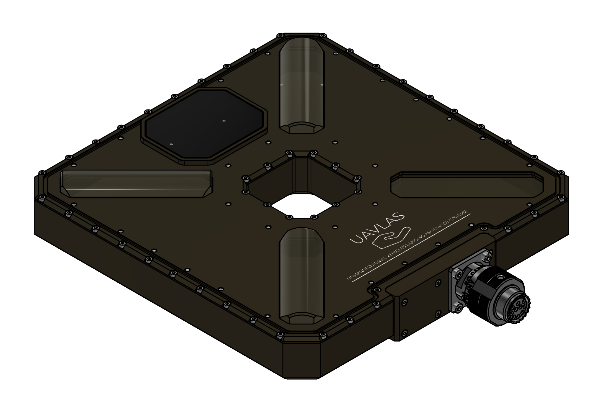
Figure: ULSDV-XS-G3-TX Transmitter
Receiver (Onboard Unit)
The ULS-XSpot-G3 uses the shared ULSDV-HLXS-G3-RXM receiver unit, identical to the one used in ULS-Heli-G3.
- Device code: ULSDV-HLXS-G3-RXM
- Primary function: Optical IR field sensor for precision positioning
- Optical central wavelength: 940nm
System architecture uses 2 identical RXM receiver units operating with the same priority.
Both RXM units are used for redundancy and for yaw orientation estimation using a triangular method in MRX mode.
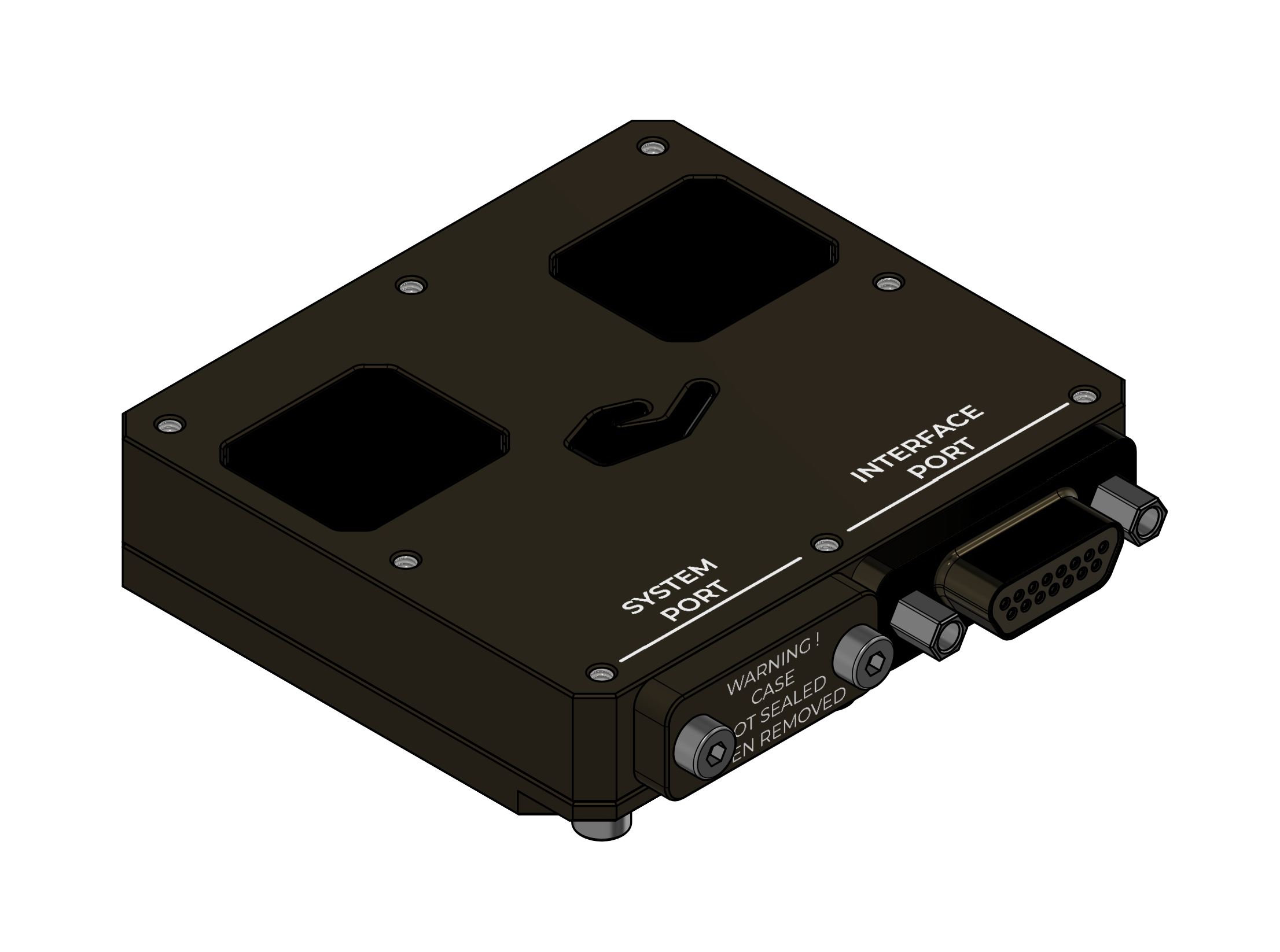
Figure: ULSDV-HLXS-G3-RXM Receiver
RS422–UART Onboard Adapter
When the autopilot has only a UART interface, the ULSDV-HLXS-G3 RS422-to-UART adapter (ULS-XX-UART-RS422) is used onboard to connect the ULSDV-HLXS-G3-RXM receiver to the autopilot.
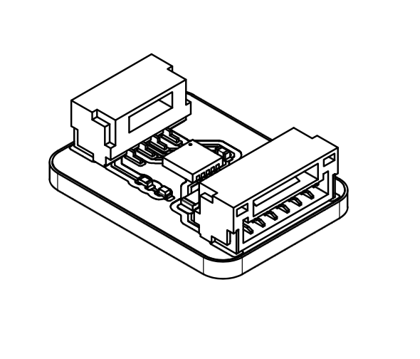
Figure: ULS-XX-UART-RS422 Onboard Adapter
USB–RS422 Ground Adapter
The ULS-XX-USB-RS422 adapter is used on the ground to connect the ULSDV-XS-G3-TX transmitter to a PC for configuration and control.
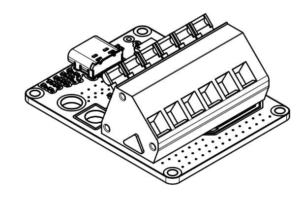
Figure: ULS-XX-USB-RS422 Ground Adapter
System Wiring Schematics

Figure: HL/XS G3 Ground-Side Wiring Schematic

Figure: HL/XS G3 Onboard Wiring Schematic
Part Numbering
| Part Number | Description |
|---|
| ULS-XSPOT-G3 | System set with transmitter and 2 identical RXM receiver units. |
| ULSDV-XS-G3-TX | Transmitter unit (tether-compatible, centre through hole design). |
| ULSDV-HLXS-G3-RXM | RXM receiver unit (identical hardware for Set A and Set B), quantity 2 per system. |
| ULS-XX-UART-RS422 | RS422-to-UART onboard adapter for connecting RXM receiver to UART-only autopilots. |
| ULS-XX-USB-RS422 | USB-to-RS422 ground adapter for connecting transmitter to PC (configuration and control). |
| TVP00WCI-13-98P | Manufacturer Amphenol. Transmitter connector type. |
| TV06RW-13-98S | Manufacturer Amphenol. Transmitter cable connector type. |
| M83513/04-B06C | Receiver connector type. |
| M83513/03-B03C | Receiver cable connector type. |
Table: Part Numbering
System Specifications
| Parameter | Value |
|---|
| Distance range (m) | 30m…50m |
| Working angle (deg) | 60 |
| Data update frequency (Hz) | 20 |
| Optical emission | IR 940nm, pulsed |
| Receiver architecture | 2 identical RXM receivers with same priority |
| Redundancy mode | Dual-RXM redundancy |
| MRX yaw estimation method | Triangular method |
| Operating mode | Tethered drone, stationary or slow-moving platform |
Table: Common Specification
| Parameter | Value |
|---|
| Field of view (deg) | 95 |
| Dimensions (mm) | 50x54 |
| Weight (g) | 50 |
| Power consumption (W) | 10 |
| Supply voltage (V) | +12V…+24V |
| Interfaces | CAN,USB,RS422 |
Table: ULSDV-HLXS-G3-RXM Receiver Specifications
Both RXM units (Set A and Set B) are the same hardware and share the specification above.
| Parameter | Value |
|---|
| Field of emitting (deg) | 30 (60 in Wide Field) |
| Centre through hole (mm) | 47 x 47 |
| Dimensions (mm) | 254 x 214 |
| Weight (g) | 1960 |
| Power consumption (W) | 20W |
| Supply voltage (V) | +18V..+24V |
| Interfaces | CAN, RS422 |
Table: ULSDV-XS-G3-TX Transmitter (Ground) Specifications
Interface Summary
The ULS-XSpot-G3 system uses optical, RS422, CAN, USB, and adapter-assisted UART connectivity depending on subsystem role and host platform capability.
- Transmitter to receiver: optical IR link, 940nm pulsed
- Transmitter to control PC: USB to RS422 adapter path
- Receiver to host system: native RS422, CAN, USB, or adapter-assisted UART
For connector, pinout, signal, and protocol definitions, refer to ULSDC-PBICD190426-ULS-XSpot-G3-ICD.
Mechanical Dimensions
| Component | Dimensions (mm) | Notes |
|---|
| ULSDV-HLXS-G3-RXM | ~ 50mm x 52mm | Without connector |
| ULSDV-XS-G3-TX | ~254mm x 214mm | Without connector. Centre through hole 47mm x 47mm for tether cable |
Table: Mechanical Dimensions
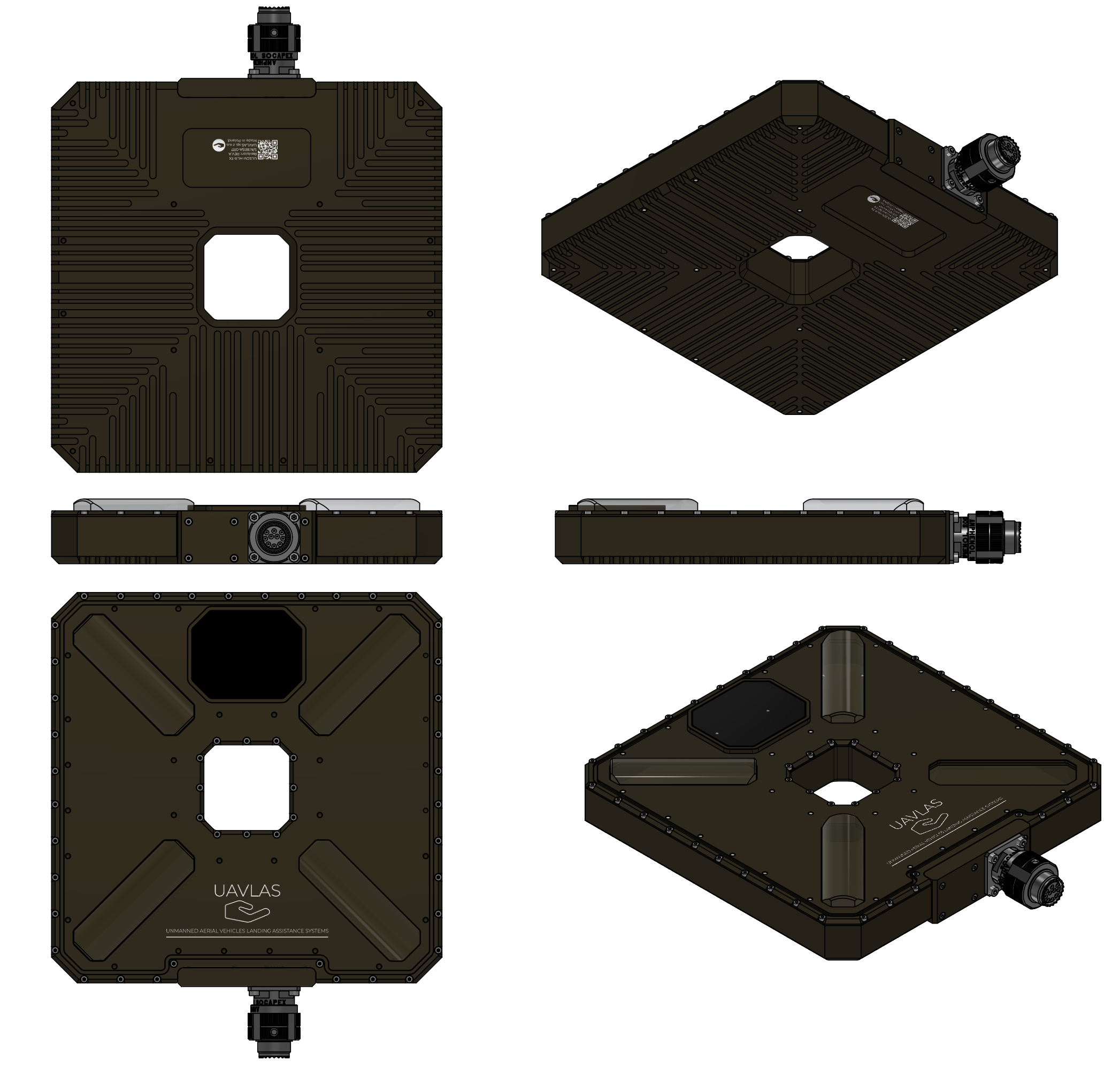
Figure: ULSDV-XS-G3-TX Projection Views (Color)
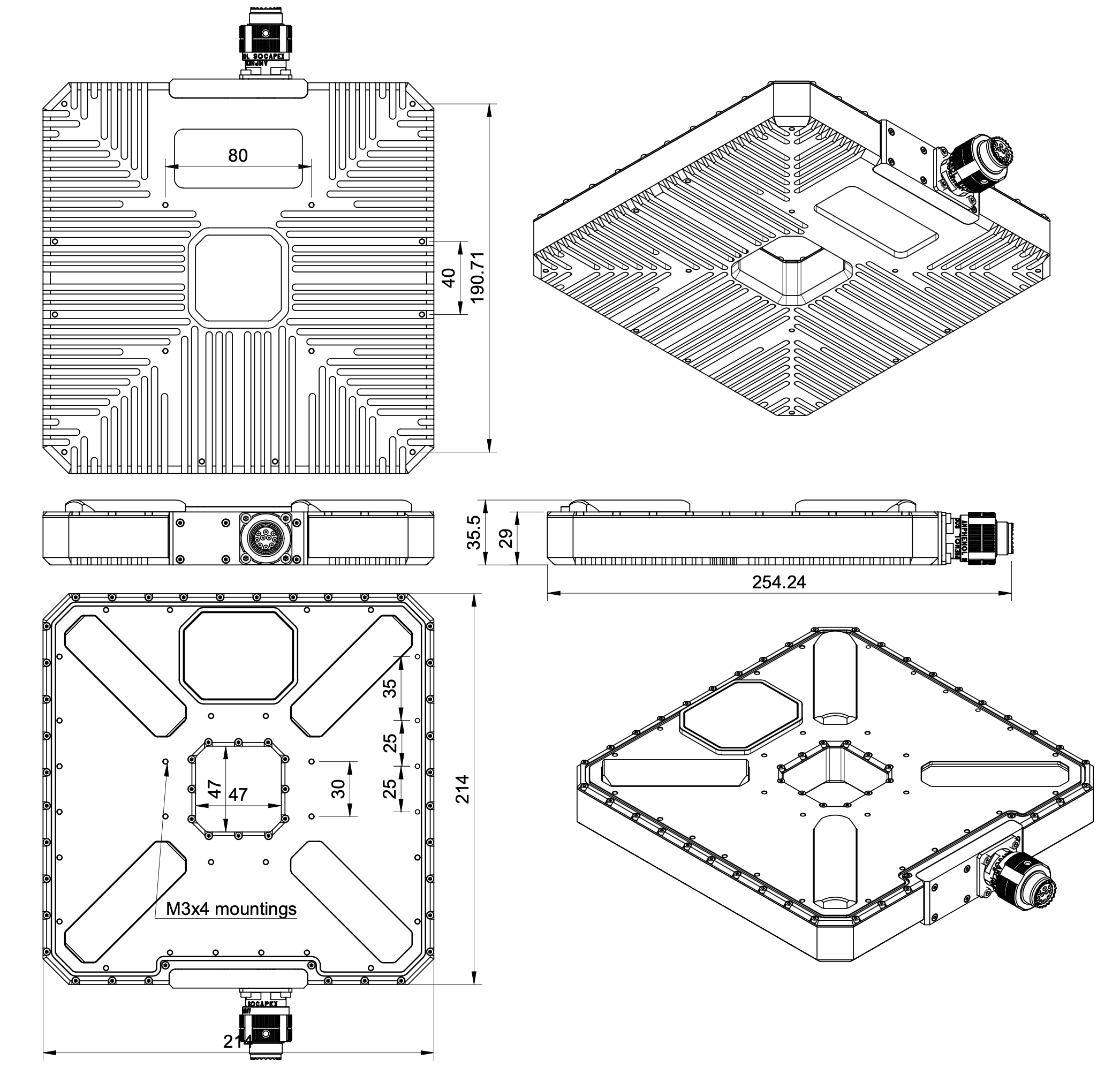
Figure: ULSDV-XS-G3-TX Transmitter Dimensions
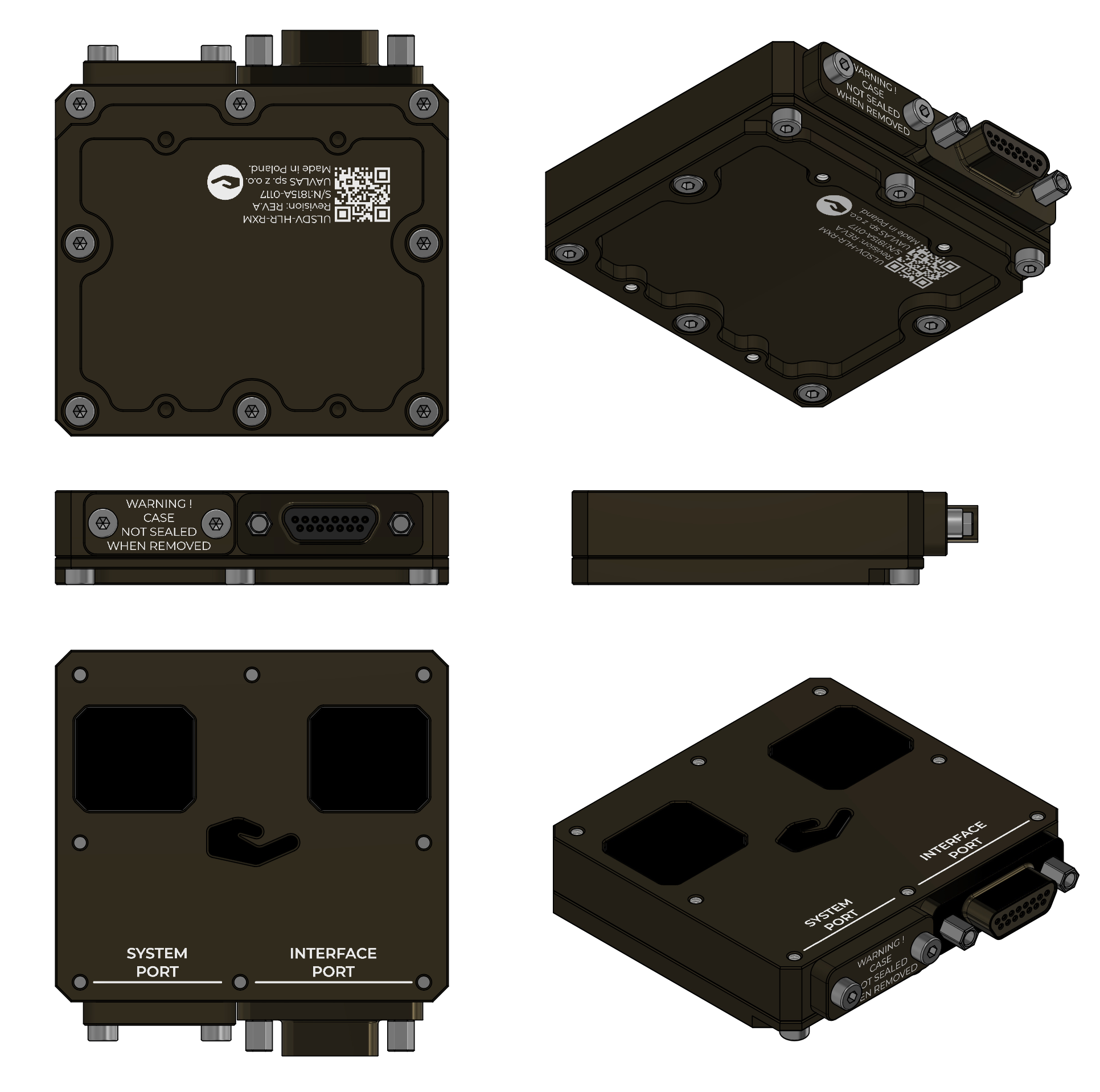
Figure: ULSDV-HLXS-G3-RXM Projection Views (Color)
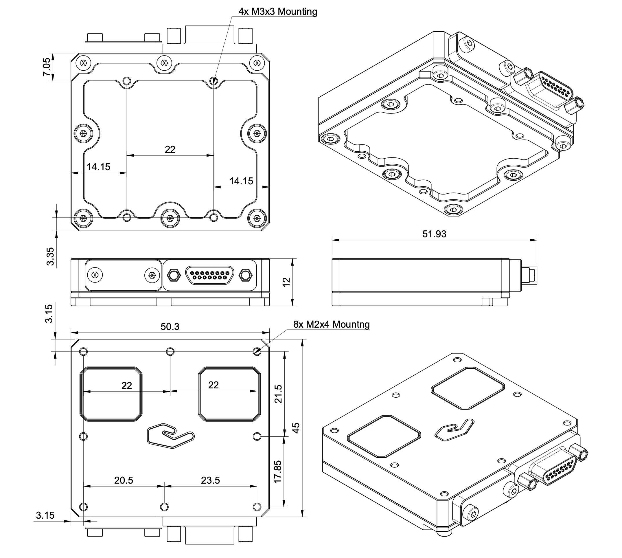
Figure: ULSDV-HLXS-G3-RXM Receiver Dimensions
| Item | Packaging Value |
|---|
| Packaging type | Rugged case |
| Unit net weight | 2500 |
| Unit gross weight | 4500 |
| Box dimensions | 180x380x400 |
Table: Packaging Information
Environmental Conditions
Equipment is designed to meet stringent military and maritime operational requirements, providing reliable performance in the most demanding environmental conditions including shipboard operations, offshore platforms, and tactical deployments.
Operating Temperature Range
- Extended operating range: -40°C to +85°C
- Meets MIL-STD-810 requirements for temperature extremes
- Arctic to desert operations capability
- No performance degradation across full temperature range
- Qualified for rapid temperature transitions and thermal shock
- Cold-soak start capability from -40°C
Humidity and Salt Fog Resistance
- Relative humidity: Up to 95% (condensing)
- Salt fog resistant per MIL-STD-810 Method 509
- Maritime environment qualified for shipboard operations
- Corrosion-resistant materials and protective coatings
- Protected against salt spray and marine atmosphere
- Suitable for offshore platform installations
Ingress Protection
- IP67 rated (Dust tight and water immersion resistant)
- 6 - Complete protection against dust, sand, and particulate ingress
- 7 - Protected against temporary immersion in water (up to 1 meter depth for 30 minutes)
- Exceeds requirements for shipboard and maritime operations
- Protected against:
- Heavy rain and sea spray
- Temporary submersion (deck washing, wave impact)
- Sand and dust storms
- Contaminated environments
Shock and Vibration
- Vibration: MIL-STD-810 Method 514
- Helicopter vibration profile qualified
- Shipboard vibration and shock resistant
- Continuous operation during vibration
- Mechanical Shock: MIL-STD-810 Method 516
- Drop and impact qualified
- Transportation and handling shock resistant
- Crash survival design considerations
Electromagnetic Compatibility
- EMI/EMC: MIL-STD-461 compliant
- Electromagnetic interference immunity
- Low electromagnetic emissions
- RF coexistence with military avionics
- Lightning protection per MIL-STD-464
- ESD Protection: IEC 61000-4-2
- Contact discharge: ±8kV
- Air discharge: ±15kV
Storage Conditions
- Storage temperature: -55°C to +85°C
- Relative humidity: Up to 95% (condensing)
- Long-term storage in uncontrolled environments
- Sealed for preservation and long-term depot storage
Altitude and Pressure
- Operating altitude: -500m to +4500m above sea level
- Storage altitude: -500m to +12000m
- Pressure differential resistant
- Suitable for high-altitude helicopter operations
Maintenance and Serviceability
- Designed for field maintenance and repair
- Minimal preventive maintenance required
- Accessible components for service and inspection
- Environmental seals serviceable in the field
- Long service intervals suitable for deployed operations
Note: All environmental specifications are subject to final qualification testing. Contact UAVLAS for the most current test data and certification documentation. Custom environmental testing and certification to specific standards available upon request.
Optical Radiation Safety (IR Emission)
The transmitter (ground unit) emits pulsed infrared optical radiation with a centre wavelength of 940nm. The receivers are optical sensors only and do not emit optical radiation.
INFRARED RADIATION IS EMITTED FROM THE TRANSMITTER OPTICAL APERTURES WHENEVER THE UNIT IS POWERED. Do not look into the transmitter emitter apertures at close range. IR emission at 940nm is invisible and does not trigger the blink or aversion reflex, so the eye receives no natural warning of exposure.
Why This Warning Is Given
Radiation at 940nm is outside the visible range. The protective mechanisms that limit exposure to bright visible sources — the blink reflex, pupil constriction, and the instinct to look away — are not triggered by an invisible source. Exposure time is therefore limited only by operator behaviour, which is why the precautions below are given as operating instructions and not left to the operator’s judgement.
The transmitter is a positioning beacon. It is not an illumination product and is not intended to be viewed at any time.
Operating Precautions
- Do not look directly into the transmitter emitter apertures from a distance of less than 1 metre while the unit is powered.
- Treat the transmitter as emitting whenever supply voltage is applied, including when no receiver is present and no positioning data is being transferred.
- Switch emission off before working directly in front of the transmitter. Use the Illumination parameter in ULS-Tools to disable emission, or disconnect supply power.
- Do not view the powered transmitter through binoculars, telescopes, camera lenses, magnifiers, or any other light-collecting instrument. Such optics concentrate the emission and can raise the exposure at the eye by orders of magnitude compared with unaided viewing.
- Do not add, remove, or modify optical elements of the transmitter. Added optics change the emission characteristics and invalidate any photobiological classification of the unit.
- Position the transmitter so that the emission field is directed away from work positions and walkways where personnel stay for extended periods.
- Servicing personnel working inside the emission field at close range should disable emission first rather than rely on viewing distance.
Classification and Applicable Standards
| Item | Value |
|---|
| Emitter type | Incoherent IR LED array (not a laser) |
| Centre wavelength | 940nm |
| Emission mode | Pulsed |
| Applicable standard | IEC 62471 / EN 62471, Photobiological safety of lamps and lamp systems |
| Classification distance | 200mm (non-GLS source, per IEC 62471) |
| Risk group | TBD — to be entered from the IEC 62471 assessment report |
| Hazard distance | TBD — to be entered from the IEC 62471 assessment report |
Table: Optical Radiation Safety Data
The transmitter uses light emitting diodes, not laser emitters. LED sources are assessed under IEC 62471; the laser product standard IEC 60825-1 does not apply to this product.
For a 940nm source the applicable exposure limits are the retinal thermal hazard (380nm to 1400nm), the retinal thermal hazard for a weak visual stimulus (780nm to 1400nm, which applies specifically to sources that give no visual cue), and the infrared hazard to the cornea and lens (780nm to 3000nm). The corneal and lens limits are intended for chronic exposures longer than 1000s at a daily averaged irradiance of 100 W/m² or more.
Organisations operating this equipment within the European Union are additionally subject to Directive 2006/25/EC on the exposure of workers to artificial optical radiation, which requires the employer to assess worker exposure against the exposure limit values given in Annex I of that directive. UAVLAS provides the emission data needed for that assessment on request.
Compliance and Standards
- Document classification and release control as defined in metadata
- Product-specific compliance statements to be finalized for release
Use the part numbering section to identify system variants, subassemblies, and related accessories.
Change Control
All changes to this document must be reviewed and approved by the relevant technical leads and stakeholders
References
- ULSDC-PBICD190426-ULS-XSpot-G3-ICD
- ULSDC-PBOM190426-ULS-XSpot-G3-Operation-Manual
5 - ULS-XSpot-G3 Interface Control Document
Electrical, mechanical and communication interfaces of ULS-XSpot-G3 — precision positioning for tethered drones, with a tether-compatible transmitter.
ULSDC-PBICD190426 · version 0.1.6 · issued August 9, 2026
The numbered PDF is the controlled copy: download it from the portal.
Introduction
Purpose
This document defines the interfaces between ULS-XSpot-G3 components, including one tether-compatible transmitter (ULSDV-XS-G3-TX) and 2 identical, equal-priority RXM receivers (ULSDV-HLXS-G3-RXM). The dual RXM architecture is used for redundancy and for yaw orientation estimation using a triangular method in MRX mode.
ULS-XSpot-G3 shares the HL/XS G3 platform with ULS-Heli-G3. Optical, electrical, and communication interfaces are identical to ULS-Heli-G3; the only difference is the transmitter case, which has a centre through hole for tether cable passage.
Scope
This document is intended for system engineers, integrators, and developers working with ULS-XSpot-G3 systems in tethered drone applications.
Assumptions and Exclusions
- This document defines interfaces only; product selection and overview information belong in the datasheet.
- Installation, calibration, and operating procedures belong in the operation manual.
System Components
Transmitter (Ground Unit)
The ULS-XSpot-G3 transmitter (ULSDV-XS-G3-TX) is the ground-side unit that emits the optical IR positioning field. It uses the same optical, electrical, and communication design as the ULS-Heli-G3 transmitter (ULSDV-HL-G3-TX); the only difference is a through hole in the centre of the case that allows the tether cable to pass through the unit.
- Device code: ULSDV-XS-G3-TX
- Primary function: Optical IR field emission for precision positioning
- Optical emission parameters: 940nm, pulsed
- Tether-compatible design: centre through hole (47 x 47 mm) for tether cable passage
Figure: ULSDV-XS-G3-TX Transmitter
Receiver (Onboard Unit)
The ULS-XSpot-G3 uses the shared ULSDV-HLXS-G3-RXM receiver unit, identical to the one used in ULS-Heli-G3.
- Device code: ULSDV-HLXS-G3-RXM
- Primary function: Optical IR field sensor for precision positioning
- Optical central wavelength: 940nm
System architecture uses 2 identical RXM receiver units operating with the same priority.
Both RXM units are used for redundancy and for yaw orientation estimation using a triangular method in MRX mode.
Figure: ULSDV-HLXS-G3-RXM Receiver
RS422–UART Onboard Adapter
When the autopilot has only a UART interface, the ULSDV-HLXS-G3 RS422-to-UART adapter (ULS-XX-UART-RS422) is used onboard to connect the ULSDV-HLXS-G3-RXM receiver to the autopilot.
Figure: ULS-XX-UART-RS422 Onboard Adapter
USB–RS422 Ground Adapter
The ULS-XX-USB-RS422 adapter is used on the ground to connect the ULSDV-XS-G3-TX transmitter to a PC for configuration and control.
Figure: ULS-XX-USB-RS422 Ground Adapter
Interface Overview

Figure: ULS-XSpot-G3 System Interfaces Overview
Interface Summary
- Transmitter to control PC
- Transmitter to receiver optical link
- Receiver to autopilot, PC, and network interfaces
- Power distribution and interface-related electrical constraints
Physical Interfaces

Figure: ULS-XSpot-G3 Physical Interfaces Overview
Transmitter to Control PC Interface
The transmitter (ULSDV-XS-G3-TX) connects to a PC via the ULS-XX-USB-RS422 ground adapter for configuration and control.
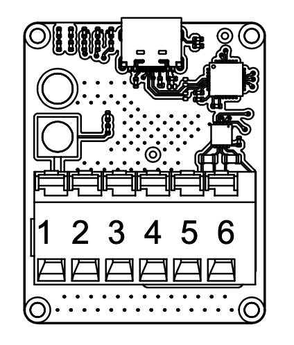
Figure: ULS-XX-USB-RS422 Adapter Pinout
| Pin | Function |
|---|
| 1 | +V supply +18V…+27V to Transmitter |
| 2 | GND |
| 3 | RS422 A RX+ (Adapter Input) |
| 4 | RS422 B RX- (Adapter Input) |
| 5 | RS422 Y TX- (Adapter Output) |
| 6 | RS422 Z TX+ (Adapter Output) |
| 7,8 | +V supply +18V…+27V Power input from battery |
*Table: ULS-XX-USB-RS422 Pinout *
Data Types
- Status information
- Control signals
- Transmitter configuration
- External IMU/COMPASS data
Connection Types
- CAN Bus – For network communication
- USB – Via ULS-XX-USB-RS422 adapter (PC side)
- RS422 – Native transmitter interface; for serial communication with external sensors
Transmitter Pinout
ULSDV-XS-G3-TX Transmitter pinout information.
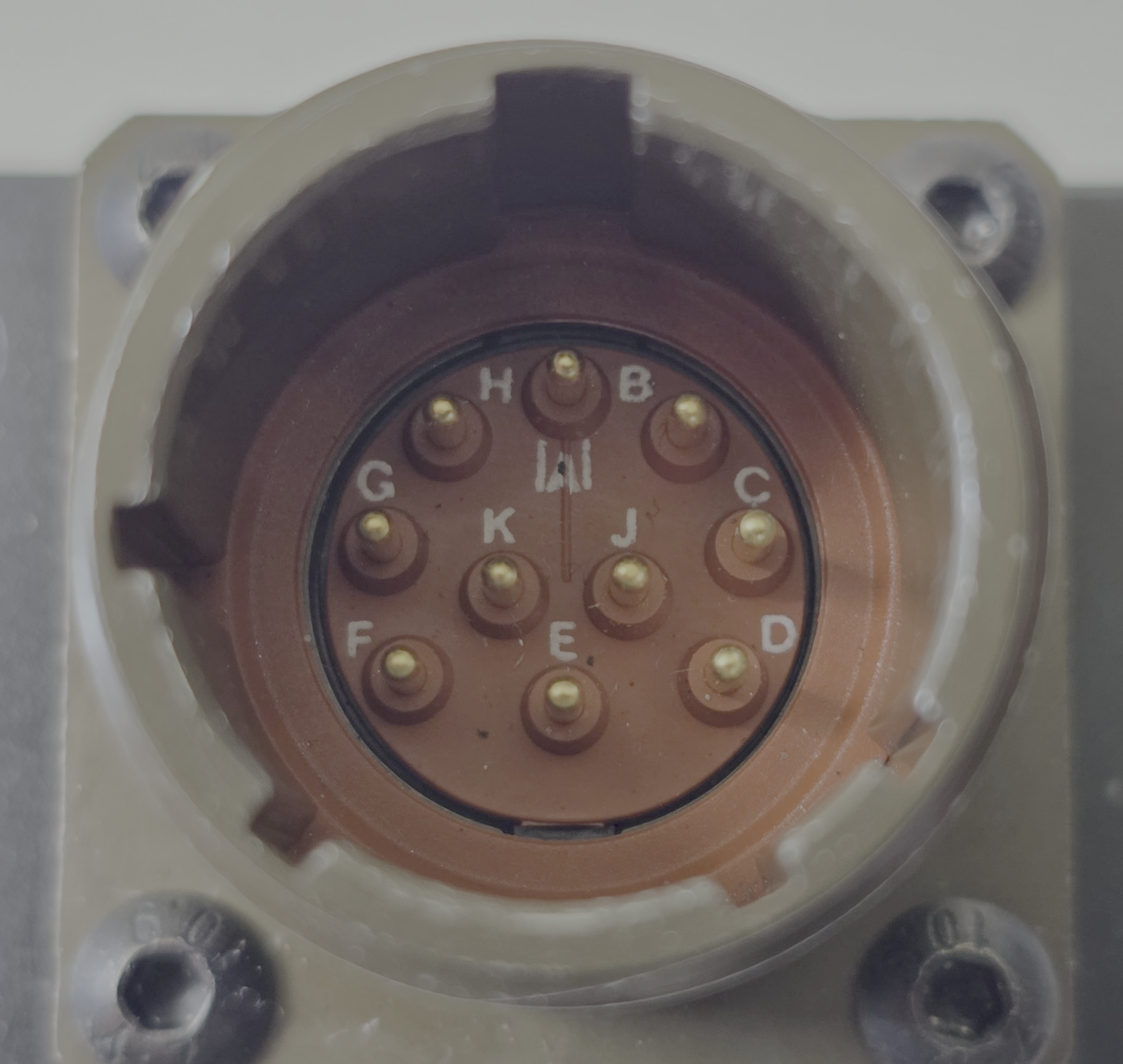
Figure: Transmitter connector
| Pin | Function |
|---|
| A | +V supply +18V…+27V |
| B | RS422 RX+ (A) |
| C | RS422 RX- (B) |
| D | RS422 TX+ (Y) |
| E | RS422 TX- (Z) |
| F | GND |
| G | C1L |
| H | C1H |
| J | GND |
| K | GND |
Table: Transmitter Connector Pinout (ULSDV-XS-G3-TX)
Do not connect or disconnect the transmitter interface under power unless approved by final hardware instructions.
The transmitter connects to a PC via the ULS-XX-USB-RS422 ground adapter (USB side to PC, RS422 side to transmitter connector).
Transmitter to Receiver Interface
The transmitter and receiver use an optical interface to exchange data. Transmission uses pulsed IR emission at 940 nanometers. Data transmission is only in the direction from the transmitter to the receiver.
Data Types
- Position encoded
- Status encoded data (transmitter orientation and instructions)
Connection Type
- Optical IR 940nm (pulsed) – Infrared optical link
The transmitter emits invisible infrared radiation whenever it is powered. Observe the precautions in the Optical Radiation Safety section before working in front of the transmitter.
Receiver Interfaces (RXM Set A and RXM Set B)
Both RXM receivers (ULSDV-HLXS-G3-RXM) are identical and have the same priority in system operation.
When the autopilot provides only a UART interface, connect the RXM receiver RS422 output through the ULS-XX-UART-RS422 onboard adapter.
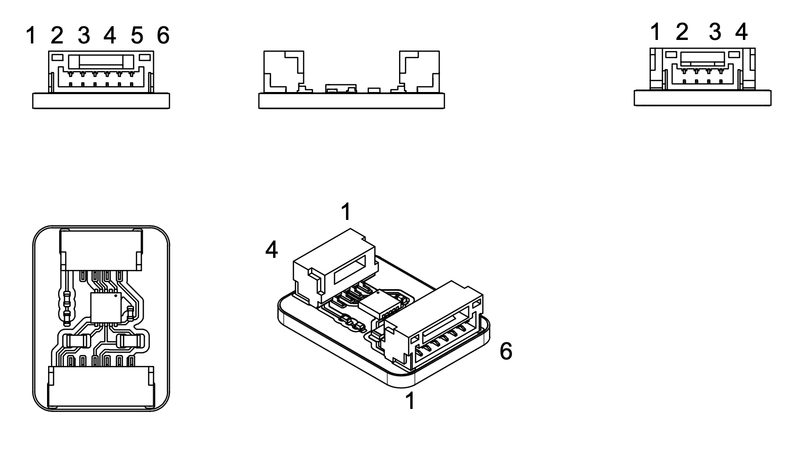
Figure: ULS-XX-UART-RS422 Adapter Pinout
| Pin | Function |
|---|
| 1 | +5V |
| 2 | UART-TX (Adapter Out) |
| 3 | UART-RX (Adapter In) |
| 4 | GND |
Table: ULSDV-XX-UART-RS422-R0 4 pin connector pinout
| Pin | Function |
|---|
| 1 | GND |
| 3 | RS422 A RX+ (Adapter Input) |
| 4 | RS422 B RX- (Adapter Input) |
| 5 | RS422 Y TX- (Adapter Output) |
| 6 | RS422 Z TX+ (Adapter Output) |
| 2 | GND |
Table: ULSDV-XX-UART-RS422-R0 6 pin connector pinout
Data Types
- MAVLink messages
- ULS-Blitz frames
- ASCII protocol
- MRX-mode yaw estimation data (triangular method)
Connection Types
- RS422 – Native receiver interface
- UART – Via ULS-XX-UART-RS422 adapter (for UART-only autopilots)
- CAN – Network communication
- USB – Direct PC connection
Receiver Pinout
ULSDV-HLXS-G3-RXM Receiver pinout information.
Both receivers (Set A and Set B) are identical, equal-priority units. The pinout is the same for both.
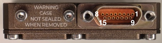
Figure: Receiver connector
| Pin | Function |
|---|
| 1 | + V supply +12V..+25V |
| 2 | C2H |
| 3 | C2L |
| 4 | GND - Ground connection |
| 5 | + V supply +12V..+25V |
| 6 | C1H |
| 7 | C1L |
| 8 | GND - Ground connection |
| 9 | + V supply +12V..+25V |
| 10 | RS422 Z |
| 11 | RS422 Y |
| 12 | RS422 A |
| 13 | RS422 B |
| 14 | GND - Ground connection |
| 15 | GND - Ground connection |
Table: ULSDV-HLXS-G3-RXM Connector Pinout
When the autopilot provides only a UART interface, connect the receiver RS422 output to the autopilot via the ULS-XX-UART-RS422 onboard adapter.
For receiver setup unscrew protection part to get access to usb connector.
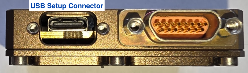
Figure: Receiver USB connector
Due hardware limitation of current revision USB connector with thin shield required
Receiver case not sealed when USB cover removed.
Electrical Interfaces

Figure: Power Distribution and Connections
Transmitter Electrical Characteristics
| Parameter | Value | Unit | Notes |
|---|
| Supply Voltage | +18…+26 | V | |
| Supply Current | 2.5 | A | |
| Power Consumption | 25 | W | |
Table: Transmitter Electrical Specifications
Tethered System Power: Transmitter may be continuously powered from a ground station power supply via the tether cable.
Receiver Electrical Characteristics (Per RXM Set)
| Parameter | Value | Unit | Notes |
|---|
| Supply Voltage | +12…+26 | V | |
| Supply Current | 1 | A | |
| Power Consumption | 10 | W | |
Table: Receiver Electrical Specifications
Communication Interfaces
Supported Communication Methods
- Optical IR 940nm pulsed link between transmitter and receiver
- RS422 for native wired subsystem interfaces
- UART via ULS-XX-UART-RS422 where required by the host autopilot
- CAN for network communication
- USB for direct PC access where supported
Data Definitions
Data Categories
- Position-encoded optical data
- Transmitter status and orientation data
- MAVLink messages
- ULS-Blitz frames
- ASCII protocol data
- MRX yaw estimation data
Message payload definitions are given in ULSDC-PBDS051125-ULS-DeCoNet Blitz Messages Specification.
Functional Interfaces

Figure: Data Flow and Functional Interfaces
Data Exchange
The ULS-XSpot-G3 system data exchange mechanism, applied to tethered drone operations:
Control PC Functions:
- Configure and view status of transmitter
- Set configuration of receivers
- Send control signals (On/off, compass override information)
- Monitor tethered operation parameters
External Equipment:
- External IMU/Compass equipment can be used to override internal IMU/compass information
- Tether management system integration for position reference
Receiver Functions:
- Accept data from transmitter over IR signal (position field information and ground unit IMU data)
- Accept NED and Attitude information from autopilot to convert coordinate system
- Multiple receivers (MRX mode) communicate to calculate vehicle orientation (YAW) using triangular method
- Send position offset data to autopilot
- Support for tethered flight modes and station-keeping
Mechanical Interfaces
| Component | Dimensions (mm) | Notes |
|---|
| ULSDV-HLXS-G3-RXM | ~ 50mm x 52mm | Without connector |
| ULSDV-XS-G3-TX | ~254mm x 214mm | Without connector. Centre through hole 47mm x 47mm for tether cable |
Table: Mechanical Dimensions
Figure: ULSDV-XS-G3-TX Projection Views (Color)
Figure: ULSDV-XS-G3-TX Transmitter Dimensions
Figure: ULSDV-HLXS-G3-RXM Projection Views (Color)
Figure: ULSDV-HLXS-G3-RXM Receiver Dimensions
The transmitter centre through hole (47mm x 47mm) is reserved for tether cable passage. Do not route the tether cable across the optical emission apertures.
Environmental Conditions
Equipment is designed to meet stringent military and maritime operational requirements, providing reliable performance in the most demanding environmental conditions including shipboard operations, offshore platforms, and tactical deployments.
Operating Temperature Range
- Extended operating range: -40°C to +85°C
- Meets MIL-STD-810 requirements for temperature extremes
- Arctic to desert operations capability
- No performance degradation across full temperature range
- Qualified for rapid temperature transitions and thermal shock
- Cold-soak start capability from -40°C
Humidity and Salt Fog Resistance
- Relative humidity: Up to 95% (condensing)
- Salt fog resistant per MIL-STD-810 Method 509
- Maritime environment qualified for shipboard operations
- Corrosion-resistant materials and protective coatings
- Protected against salt spray and marine atmosphere
- Suitable for offshore platform installations
Ingress Protection
- IP67 rated (Dust tight and water immersion resistant)
- 6 - Complete protection against dust, sand, and particulate ingress
- 7 - Protected against temporary immersion in water (up to 1 meter depth for 30 minutes)
- Exceeds requirements for shipboard and maritime operations
- Protected against:
- Heavy rain and sea spray
- Temporary submersion (deck washing, wave impact)
- Sand and dust storms
- Contaminated environments
Shock and Vibration
- Vibration: MIL-STD-810 Method 514
- Helicopter vibration profile qualified
- Shipboard vibration and shock resistant
- Continuous operation during vibration
- Mechanical Shock: MIL-STD-810 Method 516
- Drop and impact qualified
- Transportation and handling shock resistant
- Crash survival design considerations
Electromagnetic Compatibility
- EMI/EMC: MIL-STD-461 compliant
- Electromagnetic interference immunity
- Low electromagnetic emissions
- RF coexistence with military avionics
- Lightning protection per MIL-STD-464
- ESD Protection: IEC 61000-4-2
- Contact discharge: ±8kV
- Air discharge: ±15kV
Storage Conditions
- Storage temperature: -55°C to +85°C
- Relative humidity: Up to 95% (condensing)
- Long-term storage in uncontrolled environments
- Sealed for preservation and long-term depot storage
Altitude and Pressure
- Operating altitude: -500m to +4500m above sea level
- Storage altitude: -500m to +12000m
- Pressure differential resistant
- Suitable for high-altitude helicopter operations
Maintenance and Serviceability
- Designed for field maintenance and repair
- Minimal preventive maintenance required
- Accessible components for service and inspection
- Environmental seals serviceable in the field
- Long service intervals suitable for deployed operations
Note: All environmental specifications are subject to final qualification testing. Contact UAVLAS for the most current test data and certification documentation. Custom environmental testing and certification to specific standards available upon request.
Optical Radiation Safety (IR Emission)
The transmitter (ground unit) emits pulsed infrared optical radiation with a centre wavelength of 940nm. The receivers are optical sensors only and do not emit optical radiation.
INFRARED RADIATION IS EMITTED FROM THE TRANSMITTER OPTICAL APERTURES WHENEVER THE UNIT IS POWERED. Do not look into the transmitter emitter apertures at close range. IR emission at 940nm is invisible and does not trigger the blink or aversion reflex, so the eye receives no natural warning of exposure.
Why This Warning Is Given
Radiation at 940nm is outside the visible range. The protective mechanisms that limit exposure to bright visible sources — the blink reflex, pupil constriction, and the instinct to look away — are not triggered by an invisible source. Exposure time is therefore limited only by operator behaviour, which is why the precautions below are given as operating instructions and not left to the operator’s judgement.
The transmitter is a positioning beacon. It is not an illumination product and is not intended to be viewed at any time.
Operating Precautions
- Do not look directly into the transmitter emitter apertures from a distance of less than 1 metre while the unit is powered.
- Treat the transmitter as emitting whenever supply voltage is applied, including when no receiver is present and no positioning data is being transferred.
- Switch emission off before working directly in front of the transmitter. Use the Illumination parameter in ULS-Tools to disable emission, or disconnect supply power.
- Do not view the powered transmitter through binoculars, telescopes, camera lenses, magnifiers, or any other light-collecting instrument. Such optics concentrate the emission and can raise the exposure at the eye by orders of magnitude compared with unaided viewing.
- Do not add, remove, or modify optical elements of the transmitter. Added optics change the emission characteristics and invalidate any photobiological classification of the unit.
- Position the transmitter so that the emission field is directed away from work positions and walkways where personnel stay for extended periods.
- Servicing personnel working inside the emission field at close range should disable emission first rather than rely on viewing distance.
Classification and Applicable Standards
| Item | Value |
|---|
| Emitter type | Incoherent IR LED array (not a laser) |
| Centre wavelength | 940nm |
| Emission mode | Pulsed |
| Applicable standard | IEC 62471 / EN 62471, Photobiological safety of lamps and lamp systems |
| Classification distance | 200mm (non-GLS source, per IEC 62471) |
| Risk group | TBD — to be entered from the IEC 62471 assessment report |
| Hazard distance | TBD — to be entered from the IEC 62471 assessment report |
Table: Optical Radiation Safety Data
The transmitter uses light emitting diodes, not laser emitters. LED sources are assessed under IEC 62471; the laser product standard IEC 60825-1 does not apply to this product.
For a 940nm source the applicable exposure limits are the retinal thermal hazard (380nm to 1400nm), the retinal thermal hazard for a weak visual stimulus (780nm to 1400nm, which applies specifically to sources that give no visual cue), and the infrared hazard to the cornea and lens (780nm to 3000nm). The corneal and lens limits are intended for chronic exposures longer than 1000s at a daily averaged irradiance of 100 W/m² or more.
Organisations operating this equipment within the European Union are additionally subject to Directive 2006/25/EC on the exposure of workers to artificial optical radiation, which requires the employer to assess worker exposure against the exposure limit values given in Annex I of that directive. UAVLAS provides the emission data needed for that assessment on request.
Integration Wiring Diagrams
Figure: HL/XS G3 Ground-Side Wiring Schematic
Figure: HL/XS G3 Onboard Wiring Schematic
Part Numbering
| Part Number | Description |
|---|
| ULS-XSPOT-G3 | System set with transmitter and 2 identical RXM receiver units. |
| ULSDV-XS-G3-TX | Transmitter unit (tether-compatible, centre through hole design). |
| ULSDV-HLXS-G3-RXM | RXM receiver unit (identical hardware for Set A and Set B), quantity 2 per system. |
| ULS-XX-UART-RS422 | RS422-to-UART onboard adapter for connecting RXM receiver to UART-only autopilots. |
| ULS-XX-USB-RS422 | USB-to-RS422 ground adapter for connecting transmitter to PC (configuration and control). |
| TVP00WCI-13-98P | Manufacturer Amphenol. Transmitter connector type. |
| TV06RW-13-98S | Manufacturer Amphenol. Transmitter cable connector type. |
| M83513/04-B06C | Receiver connector type. |
| M83513/03-B03C | Receiver cable connector type. |
Table: Part Numbering
Applicable Documents
- ULSDC-PBDS190426-ULS-XSpot-G3-Datasheet
- ULSDC-PBOM190426-ULS-XSpot-G3-Operation-Manual
- ULSDC-PBDS051125-ULS-DeCoNet Blitz Messages Specification
Change Control
All changes to this document must be reviewed and approved by the relevant technical leads and stakeholders
6 - ULS-XSpot-G3 Operation Manual
Installation, setup, integration and troubleshooting of ULS-XSpot-G3 — precision positioning for tethered drones, with a tether-compatible transmitter.
ULSDC-PBOM190426 · version 0.1.5 · issued August 9, 2026
The numbered PDF is the controlled copy: download it from the portal.
Introduction
Purpose
This manual provides installation, configuration, operation, verification, and troubleshooting guidance for the ULS-XSpot-G3 system.
Scope
This manual covers one tether-compatible transmitter and 2 identical, equal-priority RXM receivers used in the ULS-XSpot-G3 architecture.
Intended Audience
This manual is intended for operators, installers, technicians, and integrators responsible for commissioning and using the system.
- WARNING: The transmitter emits invisible infrared radiation when powered. Do not look into the emitter apertures at close range. See the Optical Radiation Safety section below.
- CAUTION: Route the tether cable through the transmitter centre through hole. Do not route the cable across the optical emission apertures.
- CAUTION: Do not connect or disconnect the transmitter interface under power.
Optical Radiation Safety (IR Emission)
The transmitter (ground unit) emits pulsed infrared optical radiation with a centre wavelength of 940nm. The receivers are optical sensors only and do not emit optical radiation.
INFRARED RADIATION IS EMITTED FROM THE TRANSMITTER OPTICAL APERTURES WHENEVER THE UNIT IS POWERED. Do not look into the transmitter emitter apertures at close range. IR emission at 940nm is invisible and does not trigger the blink or aversion reflex, so the eye receives no natural warning of exposure.
Why This Warning Is Given
Radiation at 940nm is outside the visible range. The protective mechanisms that limit exposure to bright visible sources — the blink reflex, pupil constriction, and the instinct to look away — are not triggered by an invisible source. Exposure time is therefore limited only by operator behaviour, which is why the precautions below are given as operating instructions and not left to the operator’s judgement.
The transmitter is a positioning beacon. It is not an illumination product and is not intended to be viewed at any time.
Operating Precautions
- Do not look directly into the transmitter emitter apertures from a distance of less than 1 metre while the unit is powered.
- Treat the transmitter as emitting whenever supply voltage is applied, including when no receiver is present and no positioning data is being transferred.
- Switch emission off before working directly in front of the transmitter. Use the Illumination parameter in ULS-Tools to disable emission, or disconnect supply power.
- Do not view the powered transmitter through binoculars, telescopes, camera lenses, magnifiers, or any other light-collecting instrument. Such optics concentrate the emission and can raise the exposure at the eye by orders of magnitude compared with unaided viewing.
- Do not add, remove, or modify optical elements of the transmitter. Added optics change the emission characteristics and invalidate any photobiological classification of the unit.
- Position the transmitter so that the emission field is directed away from work positions and walkways where personnel stay for extended periods.
- Servicing personnel working inside the emission field at close range should disable emission first rather than rely on viewing distance.
Classification and Applicable Standards
| Item | Value |
|---|
| Emitter type | Incoherent IR LED array (not a laser) |
| Centre wavelength | 940nm |
| Emission mode | Pulsed |
| Applicable standard | IEC 62471 / EN 62471, Photobiological safety of lamps and lamp systems |
| Classification distance | 200mm (non-GLS source, per IEC 62471) |
| Risk group | TBD — to be entered from the IEC 62471 assessment report |
| Hazard distance | TBD — to be entered from the IEC 62471 assessment report |
Table: Optical Radiation Safety Data
The transmitter uses light emitting diodes, not laser emitters. LED sources are assessed under IEC 62471; the laser product standard IEC 60825-1 does not apply to this product.
For a 940nm source the applicable exposure limits are the retinal thermal hazard (380nm to 1400nm), the retinal thermal hazard for a weak visual stimulus (780nm to 1400nm, which applies specifically to sources that give no visual cue), and the infrared hazard to the cornea and lens (780nm to 3000nm). The corneal and lens limits are intended for chronic exposures longer than 1000s at a daily averaged irradiance of 100 W/m² or more.
Organisations operating this equipment within the European Union are additionally subject to Directive 2006/25/EC on the exposure of workers to artificial optical radiation, which requires the employer to assess worker exposure against the exposure limit values given in Annex I of that directive. UAVLAS provides the emission data needed for that assessment on request.
System Overview
ULS-XSpot-G3 is a tethered drone precision optical positioning system built around a tether-compatible ground transmitter (ULSDV-XS-G3-TX) and 2 equal-priority RXM onboard receivers (ULSDV-HLXS-G3-RXM). The system supports redundant onboard sensing and MRX-based yaw estimation for tethered flight and landing support.
ULS-XSpot-G3 uses the same HL/XS G3 platform as ULS-Heli-G3. Installation, configuration, and operating procedures are identical, except for the tether routing through the transmitter centre through hole (47mm x 47mm).
Package Contents
- 1x ULSDV-XS-G3-TX ground transmitter unit
- 2x ULSDV-HLXS-G3-RXM receiver units (Set A and Set B)
- 1x ULS-XX-USB-RS422 adapter (ground configuration)
- 2x ULS-XX-UART-RS422 onboard adapters (receiver-to-autopilot UART interface)
- Cables and mounting hardware
- Documentation package (may supply in online form)
System Requirements
- Transmitter power: +18V…+26V, 2.5A
- RXM receiver power (each): +12V…+26V, 1A
- Supported autopilots: Ardupilot and PX4 based systems (MAVLink V2), or any host supporting RS422/CAN/UART ULS protocols
Installation
Wiring Schematics
Figure: HL/XS G3 Ground-Side Wiring Schematic
Figure: HL/XS G3 Onboard Wiring Schematic
Transmitter Installation
The ULSDV-XS-G3-TX transmitter is a tether-compatible ground unit with a centre through hole for tether cable passage.
Figure: ULSDV-XS-G3-TX Transmitter
Figure: ULSDV-XS-G3-TX Dimensions
- Mounting instructions: device can be mounted from top side or from bottom side. Use corresponding M3 screws to mount device on place. 3D model and pad example can be provided by UAVLAS under request.
- Orientation requirements: The device must be positioned with the optical elements facing upward. Make sure that no foreign objects obstruct the optical elements within the transmitter’s entire field of view.
- Tether routing: route the tether cable through the centre through hole (47mm x 47mm) before mounting. The tether must not cross the optical emission apertures.
Receiver Installation
Both receivers are identical and operate with equal priority.
Figure: ULSDV-HLXS-G3-RXM Receiver
Figure: ULSDV-HLXS-G3-RXM Dimensions
- Receivers location and orientation: The device must be positioned with the optical elements facing downward. Ensure that the optical elements are not obstructed by foreign objects within the transmitter’s entire field of view.
- Install the receivers at least 0.5 meters apart; this will ensure reliable operation in MRX mode even if one of the receivers moves out of the system’s field of view. Typically, the first receiver (the one connected to the main autopilot) is located near the center of the landing point, and the second receiver is located at the tail. The maximum installation distance is 3 meters.
Configuration
Connecting Transmitter to PC
Use the ULS-XX-USB-RS422 adapter to connect the transmitter RS422 interface to a PC USB port for configuration and control via ULS-Tools software.
Figure: ULS-XX-USB-RS422 Ground Adapter
Figure: ULS-XX-USB-RS422 Adapter Pinout
Connecting Receiver to UART Autopilot
When the autopilot provides only a UART interface, use the ULS-XX-UART-RS422 onboard adapter between the receiver RS422 output and the autopilot UART port.
Figure: ULS-XX-UART-RS422 Onboard Adapter
Figure: ULS-XX-UART-RS422 Onboard Adapter Pinout
Receiver Pinout
ULSDV-HLXS-G3-RXM Receiver pinout information.
Both receivers (Set A and Set B) are identical, equal-priority units. The pinout is the same for both.
Figure: Receiver connector
| Pin | Function |
|---|
| 1 | + V supply +12V..+25V |
| 2 | C2H |
| 3 | C2L |
| 4 | GND - Ground connection |
| 5 | + V supply +12V..+25V |
| 6 | C1H |
| 7 | C1L |
| 8 | GND - Ground connection |
| 9 | + V supply +12V..+25V |
| 10 | RS422 Z |
| 11 | RS422 Y |
| 12 | RS422 A |
| 13 | RS422 B |
| 14 | GND - Ground connection |
| 15 | GND - Ground connection |
Table: ULSDV-HLXS-G3-RXM Connector Pinout
When the autopilot provides only a UART interface, connect the receiver RS422 output to the autopilot via the ULS-XX-UART-RS422 onboard adapter.
For receiver setup unscrew protection part to get access to usb connector.
Figure: Receiver USB connector
Due hardware limitation of current revision USB connector with thin shield required
Receiver case not sealed when USB cover removed.
Transmitter Pinout
ULSDV-XS-G3-TX Transmitter pinout information.
Figure: Transmitter connector
| Pin | Function |
|---|
| A | +V supply +18V…+27V |
| B | RS422 RX+ (A) |
| C | RS422 RX- (B) |
| D | RS422 TX+ (Y) |
| E | RS422 TX- (Z) |
| F | GND |
| G | C1L |
| H | C1H |
| J | GND |
| K | GND |
Table: Transmitter Connector Pinout (ULSDV-XS-G3-TX)
Do not connect or disconnect the transmitter interface under power unless approved by final hardware instructions.
The transmitter connects to a PC via the ULS-XX-USB-RS422 ground adapter (USB side to PC, RS422 side to transmitter connector).
ULS-XSpot-G3 is currently in pre-production stage. Use ULS-Tools Beta for configuration and firmware update:
https://github.com/UAVLAS/ULSTools-Beta/releases/
Use the adapters listed in this manual to connect each device to a PC and complete configuration in ULS-Tools before field operation.
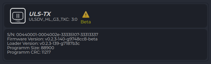
Figure: ULS-Tools Device Dashboard
- Connect the transmitter through the ULS-XX-USB-RS422 adapter.
- Open transmitter settings and verify communication parameters.
- Set required operating parameters and click Apply Config.
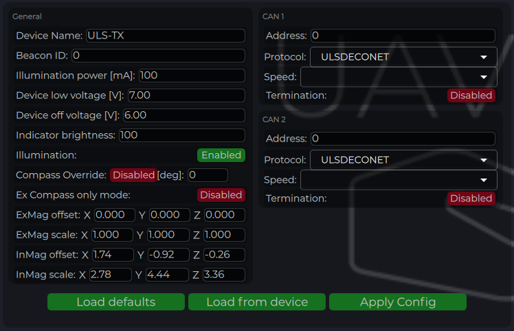
Figure: ULS-Tools Transmitter Configuration
| Parameter | Description |
|---|
| Device Name | Name shown for the transmitter in ULS-Tools. |
| Beacon ID | Transmitter iD to be transmitter to receiver over R signal (functionality under request) |
| Device Illumination Power | IR emitter power scaling (100 for nominal operation). |
| Device Low Voltage | Voltage level where low-voltage warning is activated. |
| Device Off Voltage | Voltage level where IR emitters are disabled to prevent over-discharge. |
| Indicator Brightness | Brightness level of the transmitter status LED indicator. |
| Illumination | Enables or disables transmitter emission during configuration and operation. |
| Compass Override [deg] | Fixed heading override for installations that require manual heading alignment. |
| External Compass Only | Forces system to use only external compass data when enabled. |
| Magnetometer Offset/Scale | Calibration values for internal or external (“Ex”) magnetometer. |
| CAN Address/Speed | CAN bus node address and bitrate settings. |
| CAN Protocol | Protocol selection (ULS DECENT with ULSBlitz messages supported) Custom protocols are possible |
| CAN Termination | If system has inbuilt termination resistor this option can activate it |
Table: Transmitter Configuration Parameters
- Connect each receiver and configure one at a time.
- Set UART protocol/baud rate to match autopilot serial configuration.
- For dual-receiver installation, verify MRX-related parameters and offsets.
- Click Apply Config after each update.
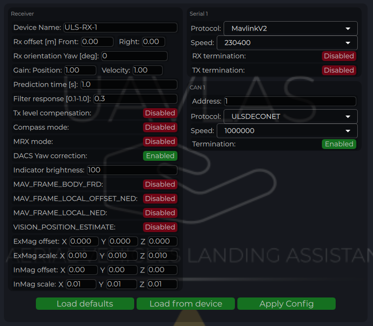
Figure: ULS-Tools Receiver Configuration
| Parameter | Description |
|---|
| Device Name | Name shown for the receiver in ULS-Tools. |
| Receiver Offset (Front, Right) [m] | Receiver position relative to vehicle reference point for MRX/yaw calculations. |
| Rx orientation | Receiver YAW installation orientation relative to vehicle front |
| Prediction Time [s] | Position prediction window used to smooth short signal interruptions. |
| Filter Response | Receiver position filter response tuning (higher is faster, lower is smoother). |
| Tx Level Compensation | Compensation for transmitter pan/tilt motion on moving platforms. |
| Compass Mode | Enables use of ground compass data in receiver calculations. |
| MRX Mode | Enables dual-receiver mode for yaw and redundancy features. |
| DACS Yaw Correction | Disable and enable Distance and Azimuth Correction System |
| Indicator Brightness | Brightness level of receiver status indicator. |
| Magnetometer Offset/Scale | Calibration values for internal or external (“Ex”) magnetometer. (under implementation) |
| CAN Address/Speed | CAN bus node address and bitrate settings. |
| CAN Protocol | Protocol selection (ULS DECENT with ULSBlitz messages supported) Custom protocols are possible |
| CAN Termination | If system has inbuilt termination resistor this option can activate it |
| UART Protocol | Protocol selection for autopilot communication (for example MavlinkV2). |
| UART Baud Rate | Serial baud rate; must match autopilot serial port settings. |
| UART Termination | If system has inbuilt termination resistor this option can activate it |
Table: Receiver Configuration Parameters
Compass Calibration (Ground Unit)
After installation, check compass behavior and perform calibration if required.
- Press Reset calibrations.
- Rotate the ground unit through multiple orientations to fill calibration charts.
- Press Apply calibration and Apply Config.
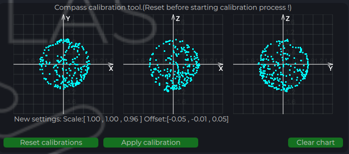
Figure: ULS-Tools Compass Calibration
- Confirm live device telemetry is visible in charts.
- Verify stable IMU and system parameter traces before flight tests.
- Confirm receiver link and valid position updates prior to autopilot integration tests.
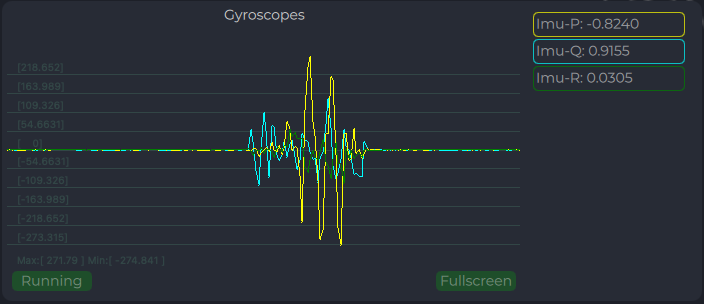
Figure: ULS-Tools System Parameters Chart
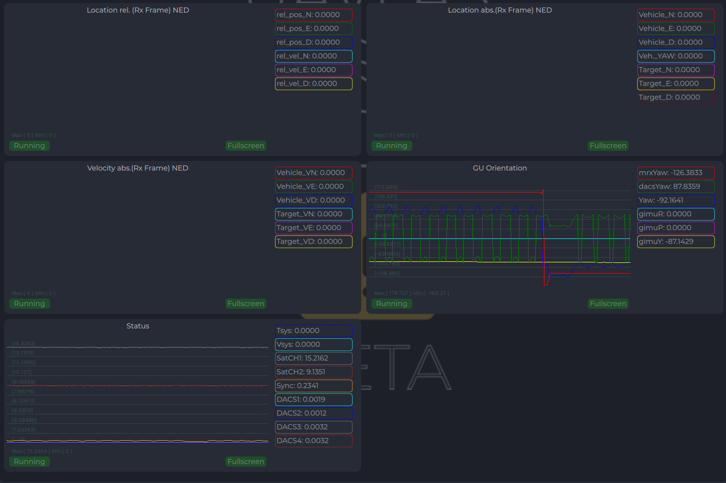
Figure: ULS-Tools Receiver Charts
Integration Instructions for Ardupilot Based Systems
Preparing for Integration
- Download the latest version of ULS-Tools (Beta). It is recommended to connect all devices to a PC and update firmware for all UAVLAS devices before proceeding.
- Update the autopilot to the latest Arducopter version.
- Configure the transmitter in ULS-Tools
- Configure both receivers in ULS-Tools
The system communicates with Ardupilot using the MavlinkV2 protocol (supports MAV_FRAME_BODY_FRD).
Autopilot Configuration
Setup PLND Section
| Param | Value | Comment |
|---|
| PLND_ENABLED | 1 | Enable the precision landing module |
| PLND_TYPE | 1 | Use type = 1 to enable UAVLAS sensor over the companion computer driver |
Table: Ardupilot PLND Section Parameters
All other PLND parameters should remain at defaults, or be set according to your vehicle requirements.
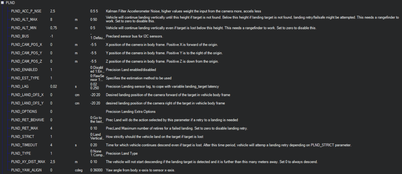
Figure: PLND Configuration Example
It is recommended to test several Kalman filter options during test flights (or switch it off) to achieve the best performance.
Set Up Serial Communication in SERIALx Section
| Param | Value | Comment |
|---|
| SERIAL2_BAUD | 230 | Baud rate — must match the receiver UART baud rate setting |
| SERIAL2_OPTIONS | 0 | Default |
| SERIAL2_PROTOCOL | 2 | MAVlink2 protocol |
Table: Ardupilot SERIALx Section Parameters
Set up serial stream rates in the SRx section. The sensor requires the following data from the autopilot:
| Param | Value | Comment |
|---|
| SR2_EXTRA1 (or MAV2_EXTRA1) | 20 | Attitude stream at 20 Hz — required for compass mode yaw orientation |
| SR2_POSITION (or MAV2_POSITION) | 20 | Optional — Vehicle LOCAL_POSITION_NED stream at 20 Hz for absolute target position calculation |
Table: Ardupilot SRx Stream Rate Parameters
Check Setup
When configuration and wiring are correct, GPS is available, and the receiver is in the field of view of the transmitter, you will see the LANDING_TARGET MAVLink message in the MAVLink Inspector (Mission Planner example shown):
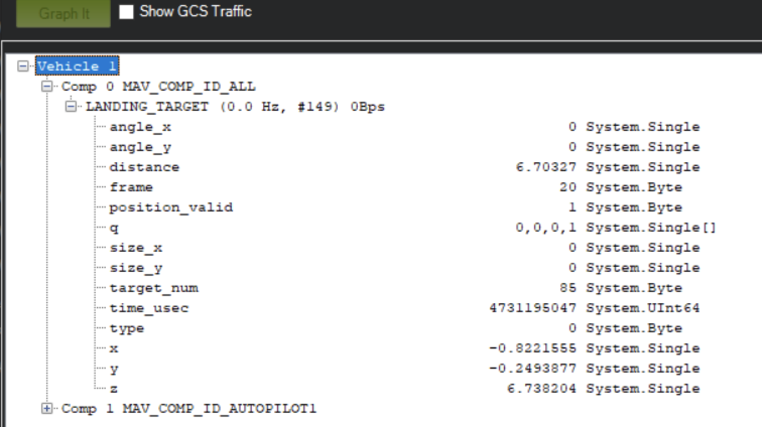
Figure: LANDING_TARGET Message in MAVLink Inspector
Setup Precision Loiter Mode
Attach any unused switch to the PrecLoiter option to enable precision loiter mode:
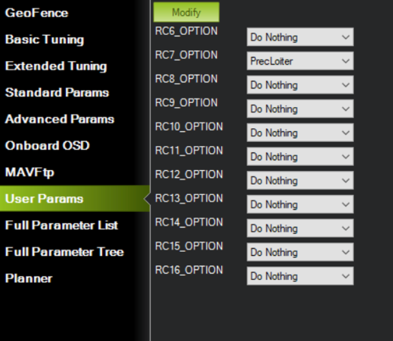
Figure: PrecLoiter Switch Configuration
Activate the switch and confirm messages “PrecLoiter: LOW” and “PrecLoiter: HIGH” appear. After a test flight above the target, check telemetry for PL offset data.
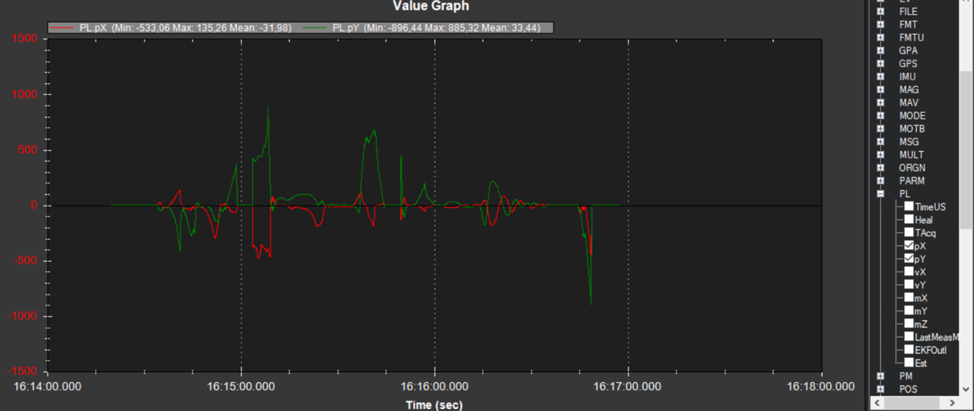
Figure: Telemetry Data Showing PL Offsets
PID Tuning
In case of oscillations or instability during landing, check the PID parameters in Ardupilot Extended Tuning.
It is recommended to tune Position XY, Velocity XY, and Loiter Speed for the best performance:
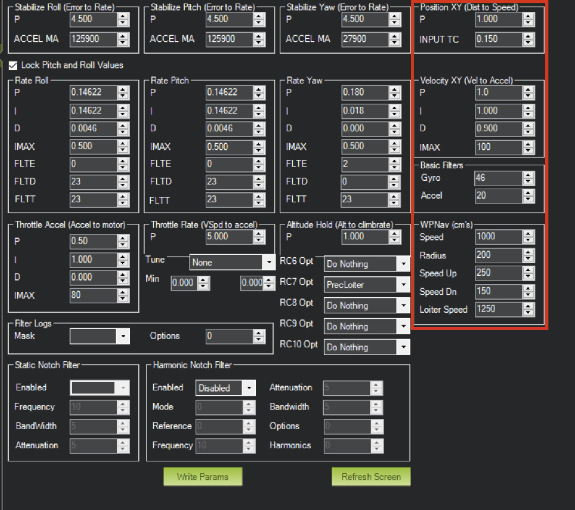
Figure: Ardupilot Extended Tuning Parameters
Settings of Velocity XY P = 0.8, I = 0.2, D = 0.6 have worked well for some customers as a starting point.
It is recommended to start PID testing and performance validation in Precision Loiter mode before enabling full precision landing.
For additional information, see the Ardupilot documentation at https://ardupilot.org/ardupilot/
Integration Instructions for PX4 Based Systems
Preparing for Integration
- Download the latest version of ULS-Tools (Beta). It is recommended to connect all devices to a PC and update firmware for all UAVLAS devices before proceeding.
- Update the autopilot to the latest PX4 version.
- Configure the transmitter in ULS-Tools.
- Configure both receivers in ULS-Tools.
The system communicates with PX4 using the MavlinkV2 protocol (supports MAV_FRAME_LOCAL_NED).
Values are provided as an example (Pixhawk4-mini AP):
| PX4 Parameter | Value | Comment |
|---|
| MAV_1_CONFIG | TELEM/SERIAL4 | Requires reboot to apply the next parameters |
| MAV_1_FORWARD | Enabled | Forward MAVLink messages |
| MAV_1_MODE | Onboard | Set link mode to onboard |
| SER_TEL4_BAUD | 460800_8N1 | Must match the UART baud rate set in the receiver configuration |
Table: PX4 Autopilot Configuration Parameters
Running and Testing
After configuration and wiring, power up the drone and transmitter. In QGroundControl, go to Analyze Tools → MAVLink Inspector and check for the LANDING_TARGET MAVLink message.
If the vehicle is providing a LOCAL_POSITION_NED message to the UAVLAS system and is hovering over the beacon, the field position_valid = 1 will appear in LANDING_TARGET.
To perform precision landing, create a flight plan and enable the Precision Landing option on the landing waypoint.
LANDING_TARGET may be unavailable when connected over USB. Use a telemetry channel (UART modem, etc.) to connect the drone to QGroundControl during testing.
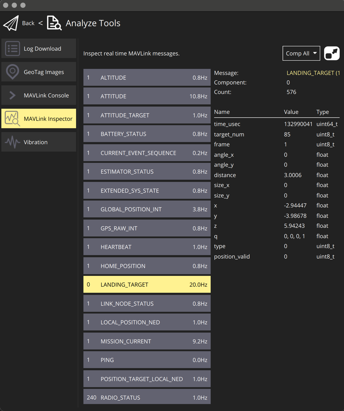
Figure: LANDING_TARGET Message in QGroundControl
For additional information, see the PX4 documentation at https://docs.px4.io/main/en/
Operating Instructions
- Power sequence: Power device after all connectors are plugged in before powering.
- Link check procedure: Link can be checked from the configuration system during system installation, as well as during operation using a third-party device via the appropriate protocols.
- Landing and approach operation notes: The vehicle’s control system independently decides on the appropriate action based on the status of the landing system. The UAVLAS system acts as a sensor—the procedure for handling abnormal situations during operation remains the responsibility of the unmanned vehicle’s control system.
- Equal-priority RXM behavior in MRX mode: Both receivers have the same priority, and either one can be used to receive system status data.
- Tethered operation: verify that the tether cable stays inside the transmitter centre through hole over the full range of tether movement.
Service and Support
The device requires no maintenance throughout its service life.
Appendices
Technical Reference
| Parameter | Value |
|---|
| Distance range (m) | 30m…50m |
| Working angle (deg) | 60 |
| Data update frequency (Hz) | 20 |
| Optical emission | IR 940nm, pulsed |
| Receiver architecture | 2 identical RXM receivers with same priority |
| Redundancy mode | Dual-RXM redundancy |
| MRX yaw estimation method | Triangular method |
| Operating mode | Tethered drone, stationary or slow-moving platform |
Table: Common Specification
| Parameter | Value |
|---|
| Field of view (deg) | 95 |
| Dimensions (mm) | 50x54 |
| Weight (g) | 50 |
| Power consumption (W) | 10 |
| Supply voltage (V) | +12V…+24V |
| Interfaces | CAN,USB,RS422 |
Table: ULSDV-HLXS-G3-RXM Receiver Specifications
Both RXM units (Set A and Set B) are the same hardware and share the specification above.
| Parameter | Value |
|---|
| Field of emitting (deg) | 30 (60 in Wide Field) |
| Centre through hole (mm) | 47 x 47 |
| Dimensions (mm) | 254 x 214 |
| Weight (g) | 1960 |
| Power consumption (W) | 20W |
| Supply voltage (V) | +18V..+24V |
| Interfaces | CAN, RS422 |
Table: ULSDV-XS-G3-TX Transmitter (Ground) Specifications
Change Control
All changes to this document must be reviewed and approved by the relevant technical leads and stakeholders
References
- ULSDC-PBDS190426-ULS-XSpot-G3-Datasheet
- ULSDC-PBICD190426-ULS-XSpot-G3-ICD