At this resource you will find all the necessary information on how to use our system as well as answers to frequent questions related to precision landing of different types of drones.
In the Application sections, you will find general information about what this type of device is best used for and general information about how to use this system.
In the specification sections you will find all available information about the technical data of the devices including mechanical and electrical parameters.
The Integration section provides detailed information on how to connect the system and configure it to work with different drone control systems.
In the FAQ sections, you will find answers to frequently asked questions.
For a quick search of the site, you can use the search form as well as the tagging system.
We will be grateful if you find inaccuracies in the description or other errors and send us a message. You can use the Feedback section on each page of the documentation.
Enjoy the exploring process!
1 - Overview
General information about UAVLAS system infrastructure.
UAV Precision landing Systems
UAVLAS (Unmanned Arial Vehicles Landing Assistance Systems) is a group of systems assisting the landing of vertical take-off / landing vehicles and fixed-wing UAVs.
The system consists of several types of devices - onboard receivers, processors and a ground emitters (beacon), communication and navigation units. The system operates in the infrared. The beacon forms a virtual grid of positions above itself; the receiver, guided by the current grid square, decides its location relative to the lighthouse.
Ground module
The ground module is equipped with a matrix of light emitting diodes, which works in the infrared range. The special arrangement of the LEDs allows the device to form a virtual grid in the space above it, with an aperture of more than 50 degrees (for ULS-XCOPTER). A specially developed radiation algorithm can significantly reduce the consumption of the device, while maintaining maximum efficiency and range of the system.
The small system consumption - this allows the emitter to work more than 30 hours continuously from a single battery. The ground module has an indication that displays the current state of the device.
The on-board module
The on-board module has small dimensions. This allows you to easily place it on almost any aircraft. A small weight (less than 10 grams for ULS-XCOPTER ) and low power consumption will save the aircraft a great deal of energy in maintaining this system. The field of view of the sensor is more than 100 degrees - this allows the receiver to “see” the ground module, even with the large inclinations of the aircraft. Special technical solutions allow the receiver to be sensitive while having good resistance to extraneous noise.
Advantages
Does not require an additional height sensor. The system allows you to independently determine the distance to the lighthouse. This provides the possibility of landing on a site whose height is significantly higher relative to the surrounding terrain.
Small overall size and low power consumption. It takes up little space on an aircraft and saves energy resources. The ground part can work for a long time on an autonomous power source.
The system is invariant to the position of the drone. The formation of the information about the angular position of the apparatus occurs on the ground. Accordingly, the roll, pitch and course of the aircraft do not affect the readings. This allows landing in gusty winds and strong vibrations of the apparatus.
It is possible to change the approach path by changing the slope of the transmitting beacon. This allows landing in places limited by a vertical obstacle (for example, a platform on the wall).
2 - ULS-Tools
UAVLAS devices configuration software.
ULS Tools software allows configuring UAVLAS devices and provide complete information of device status to help integrate system in different AP systems.
It allows updating firmware of devices as well.
Lasted version of software you can get using information on Software Download Page
Toolbar
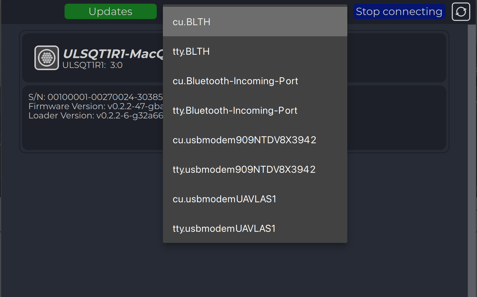
Toolbar (from left to right): “Back to Device View”, “Configs cards”, “Updates”, “Serial port”, “Connect/Disconnect”,“Refresh page”.
The program will try to automatically connect to the devices. By the way, you can press stop connecting, select port from dropdown list and press connect.
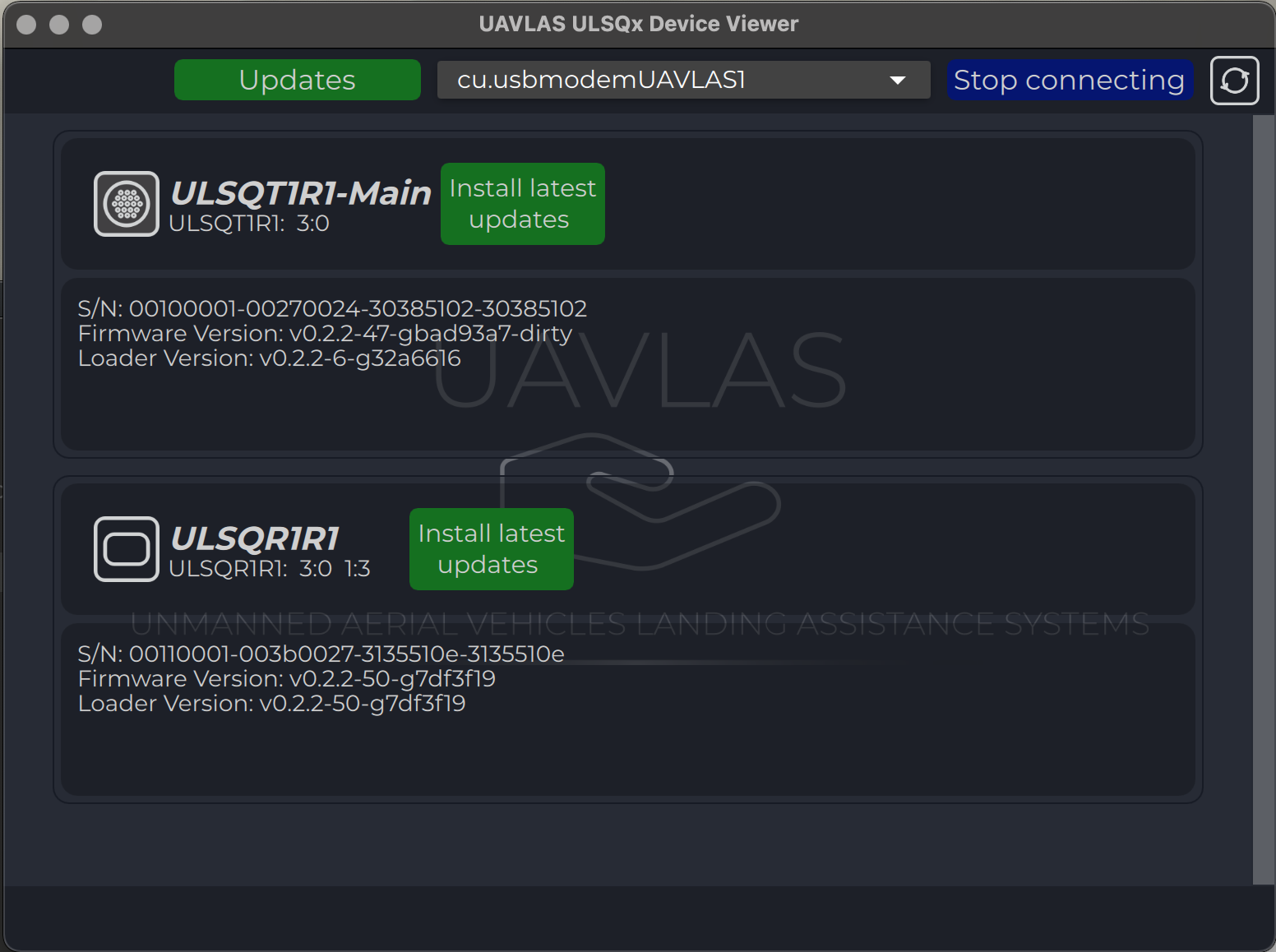
Device View
All the connected devices appear on the ain device page as icons.
Each icon contains information about the device (serial number, firmware version).
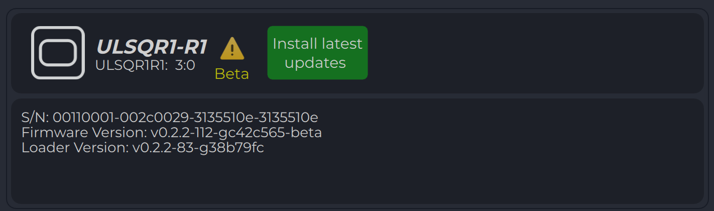
All updates information is requested from the server automatically and, in case of new updates for device are available, corresponding button appears.
You can enter the device page by pressing the device icon.
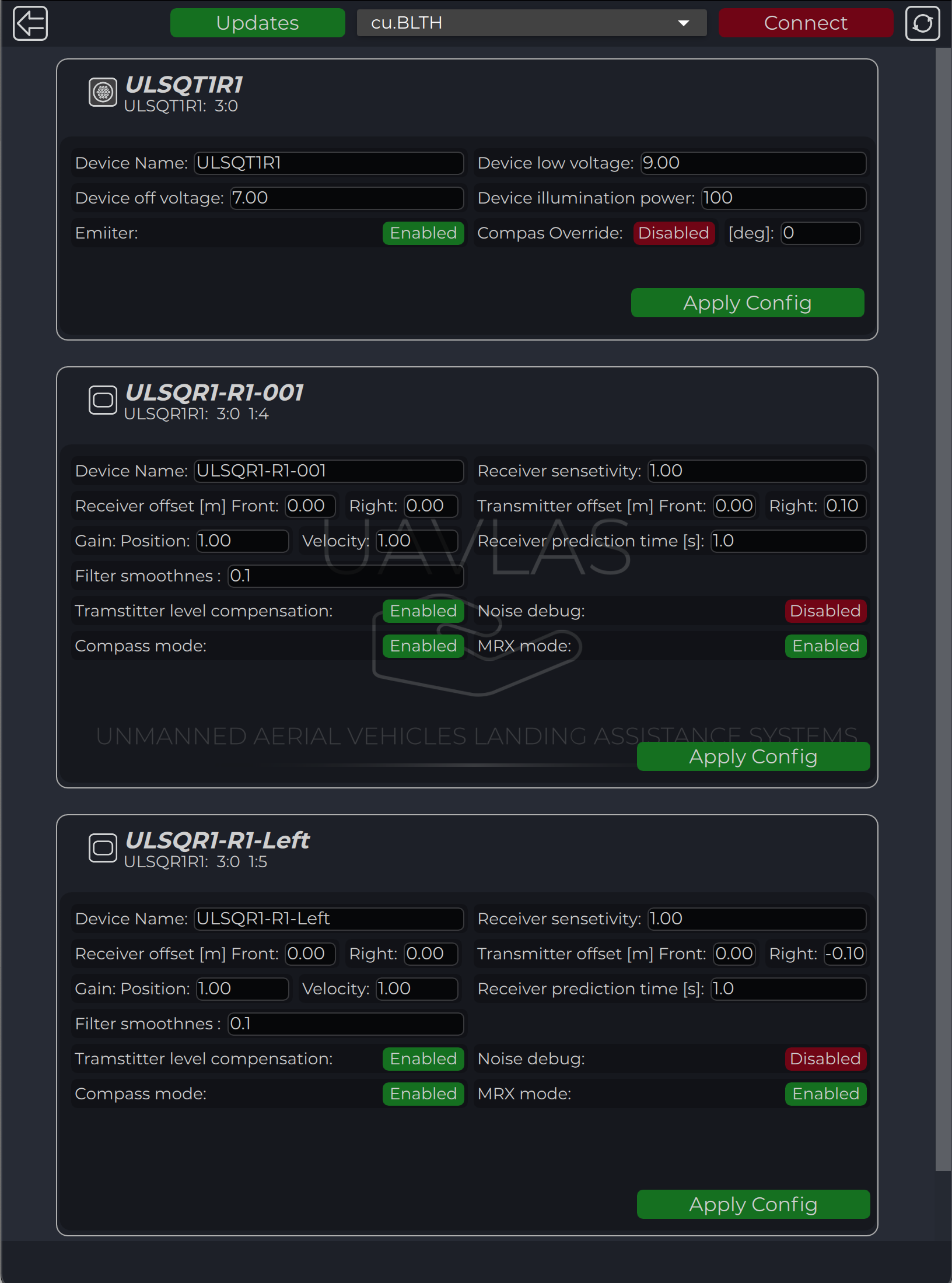
Configs cards
All connected devices appear on the configuration device page as cards.
Each card contains information about the device configuration.
You can enter the device page by pressing “Configs cards” icon on the toolbar.
Config for each device are applied individually by pressing “Apply config” button in each card.
ULS-Heli, ULS-OnNet, ULS-XSpot device support added
CAN blitz messages updates
Small issues fixed.
* Note: for Windws OS it requred to have Visual C++ Redistributable installed.you can download it here: Visual C++ Redistributable
* Note: To use latest features and firmware download Beta version of ULSTools. Betta version can contains some issues and bugs. We recommend to use sable for production. You can download Beta version here: Beta version repository
2.2 - Update Firmware
UAVLAS devices firmware update instructions.
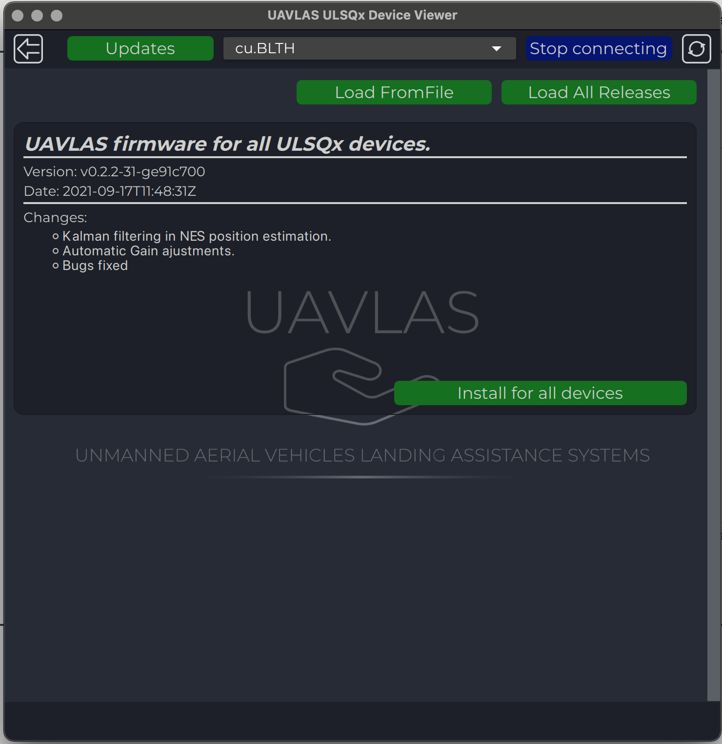
Firmware Update
Updating to last version of firmware can be done from the main device vew page.
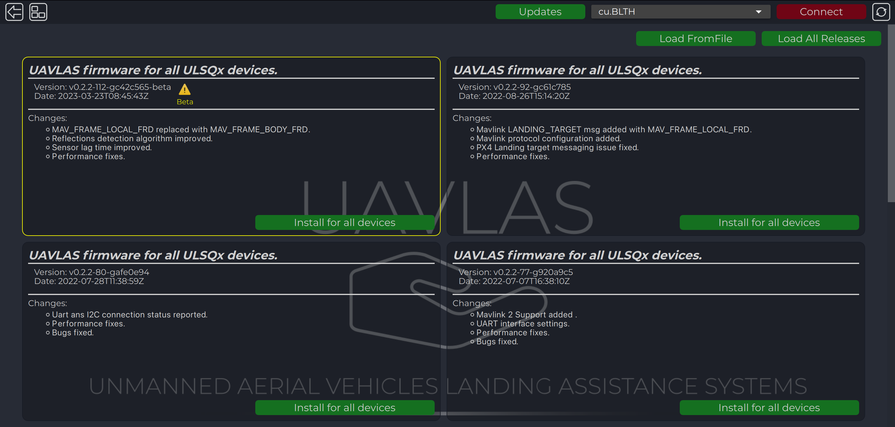
Update all devices at once or update to a specific version or from file can be done from the update page.
The last release appears on the page automatically, but you can load all releases or load firmware from a file using corresponding buttons.
After loading, use “Install for all devices” to update firmware.
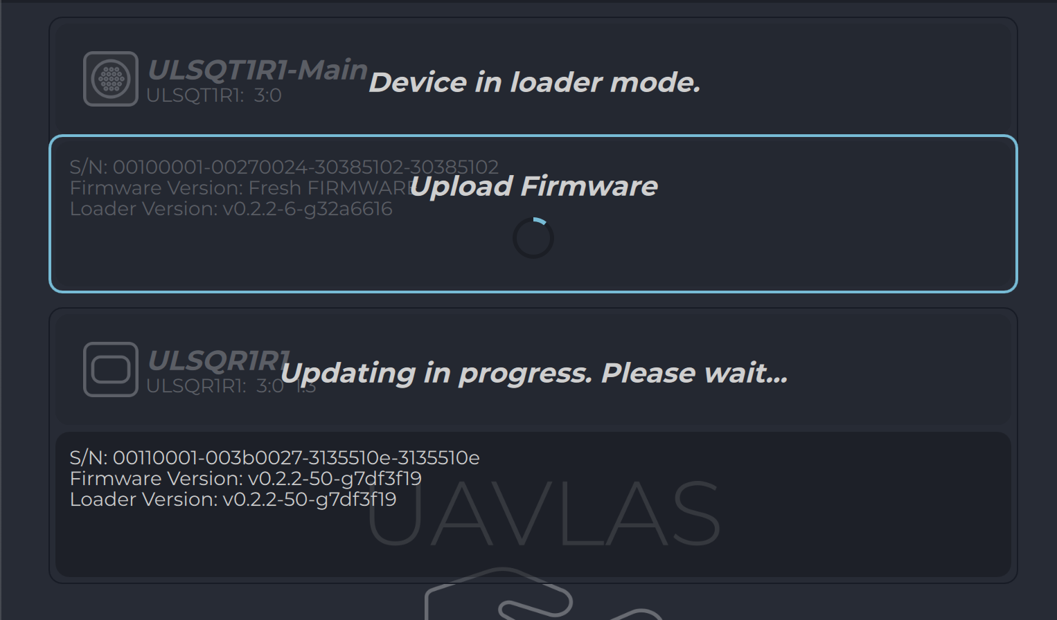
Progress of updating process are displayed on Device View Page.
Warning
DO NOT DISCONNECT ANY DEVICES OR CLOSE PROGRAM UNTIL UPDATE PROCESS COMPLIED!.
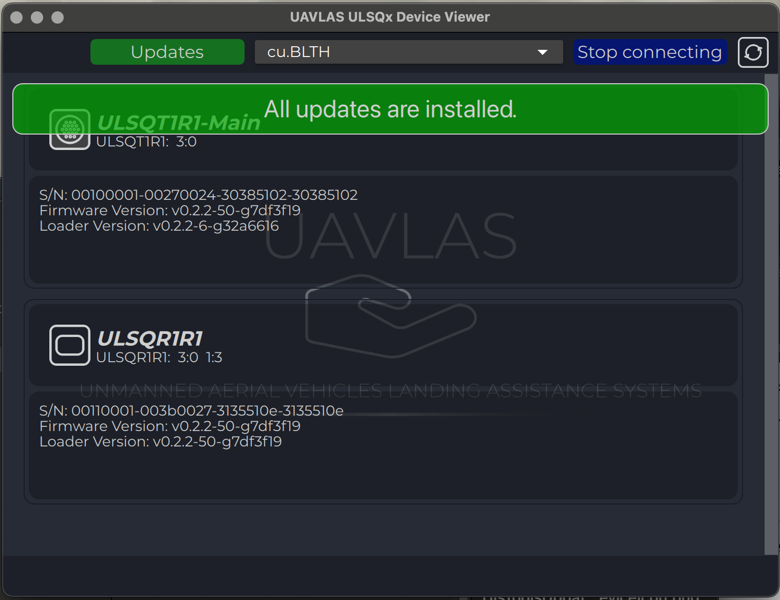
After updating you will get the corresponding message.
Firmware Update Beta version
“Beta” releases contains builds with new features and recommended for testing purposes.
Updating to beta version of firmware can be done on the update page.
Update all devices at once or update to a specific version or from a file can be done from update page.
“Beta” version is visible only if “Load all releases” pressed and marked with “Yellow” icon and border.
After loading, use “Install for all devices” to update firmware.
Progress of updating process are displayed on Device View Page.
Warning
DO NOT DISCONNECT ANY DEVICES OR CLOSE PROGRAM UNTIL UPDATE PROCESS COMPLIED!.
All devices flashed with beta version are marked with corresponding “Yellow” logo on “Device view” page
3 - ULS-XCopter
Basic information about the product line.
This series of devices is designed primarily for use on small vertical take-off and landing aircraft (up to 30 kg). The small weight and dimensions will easily accommodate the drones, even weighing 100 grams. Our customers often buy this version of the system to get acquainted with the technology and test methods of our system’s integration. The system is also popular among research companies and institutes for conducting experiments with vehicles.
It is worth mentioning that this version of the system is not supplied in a dust and moisture-proof version. However, it is possible to use the system in the professional sector. In this case, our customer himself takes measures to ensure the necessary level of protection of the device. Of course, the professional version of ULS-Heli is also available in our product line. Also, according to the feedback from our customers, we are developing a professional version of the current XCopter series.
It is well suited for monitoring delivery systems and other drone-based systems for which a reliable, repeatable accurate landing is needed.
Currently UAVLAS has released 2 generations of ULS-XCopter-G1 and ULS-XCopter-G2. The main difference of the second generation of XCopter-G2 system is the presence of DACS (Distance and Azimuth Correction System). This system improves the reliability and accuracy of range calculation and improves the functionality of the MRX mode. See Integration section for more information.
3.1 - Application
What is the best application for this series of systems? How to use it properly?
Landing on platform, emergency landing
To perform an accurate landing on the platform, it is necessary to mark out the landing area transmitter. Due to its small size, it can be easily placed even on a small platform. In case of an emergency landing, the transmitter can simply be placed on any surface and connected to a power source.
The receiver must be mounted on board of the aircraft in a line of sight with the transmitter. It is desirable to place the receiver closer to the center of the drone, but if it is not possible to place the receiver directly in the landing center area, the offset can be eliminated by adjusting the receiver accordingly.
For more information, see the integration section.
Landing on the elevated platforms
Since the system calculates the distance to the landing point by itself, there is no need to use additional tools to ensure landing on a float plane that is at a significant elevation from the surrounding environment. This will be useful when landing on masts, tall structures, large vehicles, etc. No additional adjustments are required in this case.
Landing on balcony
A special case of landing is landing on a platform accessible only from one side. For example, balconies. In this case, it is not possible to make a vertical landing. With our system, however, you can easily select the landing angle simply by orienting the transmitter in the desired direction. In this case, the receiver will continuously transmit updated data about the position of the landing site so that the trajectory of the aircraft will not be vertical. Also, in this mode, you can dynamically control the position of the drone by changing the inclination of the transmitting beacon. Please note that this function can be disabled in the receiver settings and then the landing will always be vertical regardless of the transmitter tilt (e.g. if you are landing on a moving platform).
Wireless charging stations and contactless delivery
The system can be used not only to provide a landing, but also to realize a precise hovering over the desired point. This is useful for e.g. for wireless charging systems - in which the drone is charged while in vision, or for e.g. in cases when the cargo is delivered without contact (dropped). It should be noted that our system provides not only the horizontal position shift, but also the altitude. This allows accurate positioning not only in the horizontal plane, but also in height - this is very important for wireless charging and contactless delivery.
3.2 - Specification
Detailed product specification information
Common specification:
Parameter
XCopter-G1
XCopter-G2
Distance range m.:
0.1 - 20.0
0.1 - 20.0
Working angle (deg):
60
60
Data update frequency (Hz):
20
20
Receiver (on board unit):
Parameter
XCopter-G1
XCopter-G2
Field of view (deg):
100
100
Dimensions mm :
20 x 32 x 9
20 x32 x 9
Weight g. (oz.):
10
10
Power Consumption (W):
0.3
0.3
Voltage supply (V):
5.0
5.0
Interfaces:
USB, I2C,CAN, UART
USB, I2C,CAN, UART
Transmitter (on ground)
Parameter
XCopter-G1
XCopter-G2
Field of emitting (deg):
60
60
Dimensions mm. :
50 x 50 x 20
50 x 50 x 23
Weight g.:
45
45
Power Consumption (W):
2.1
2.4
Voltage supply (V):
7.5 - 27
7.5- 27
Interfaces :
USB, CAN, UART
USB, CAN, UART
System Measurement Accuracy Diagram
Mechanical dimensions
Receiver (G2)
Transmitter (G2)
Receiver pinout
JX1 - External power and control
Pin number
XCopter-G1
XCopter-G2
1
+5V Input
+5V Input
2
UART RX
UART RX
3
UART TX
UART TX
4
CAN H
CAN H
5
CAN L
CAN L
6
USB D-
USB D-
7
USB D+
USB D+
8
I2C SCL
UART2 RX
9
I2C SDA
UART2 TX
10
GND
GND
Transmitter pinout
JX1 - External power and control
Pin number
XCopter-G1&G2
1
Vcc Input (+7.5V..+27V)
2
CAN2 H
3
CAN2 L
4
UART TX
5
UART RX
6
GND
JC1 - JC4 - Submodules connection
Pin number
XCopter-G1&G2
1
+5V Output
2
CAN1 H
3
CAN1 L
5
GND
Warning
Warning: Please note that if you use a USB cable to connect the ULS-XCopter-G2 transmitter and power is supplied via this cable, you must ensure that the cable and power supply allows at least 3A. If the power supply or cable does not allow 5V 3A to be delivered to the transmitter, the device may not work properly. In this case it is recommended to use an external power supply of 7.5-24V connected to connector JX1 - External power and control.
3.3 - Integration
Technical instructions - how to integrate and set up the system.
Ground unit installation (transmitter)
The device must be installed on a clean surface to avoid any obstacles.
The device must be installed in an open area. There must be no obstacles in the radiation field of the transmitting device. If possible, avoid installing the system near vertical surfaces that can strongly reflect infrared radiation.
The 4 holes on the bottom of the device can be used to mount the device. For fastening, use M2 screws, thread depth 2 mm.
It is allowed to install the device under a surface that is optically transparent to infrared radiation by more than 95%. Glass or transparent plastic can act as such a surface.
In this case, to increase the coverage of the system at low altitudes, it is recommended to install the transmitter below the level of the platform. This will allow you to expand the coverage of the system to a larger area during touchdown.
Note
Please note, to compensate for the loss of transmitter illumination, you can adjust the illumination power of the transmitter. To do this, place the receiver at a fixed distance from the installed transmitter (recommended 1-2 meters) and adjust the “Device illumination power” of the transmitter until the distance information on the receiver does not correspond to the actual distance. Maximum Correction for “Device illumination power” 110%
After installation, it is recommended to verify the correctness of the compass reading and, if necessary, correct the compass calibration.
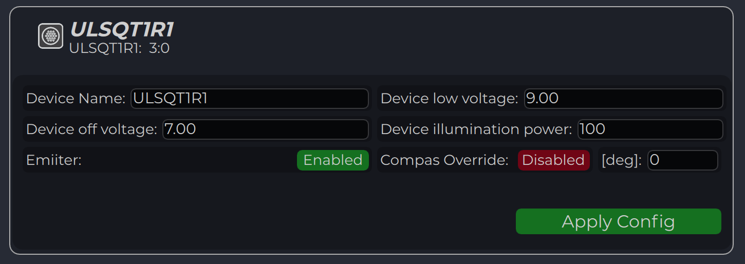
Wiring Transmitter
The transmitter only requires power to operate. The transmitter can be powered either via USB-C or via a 6-pin connector located nearby.
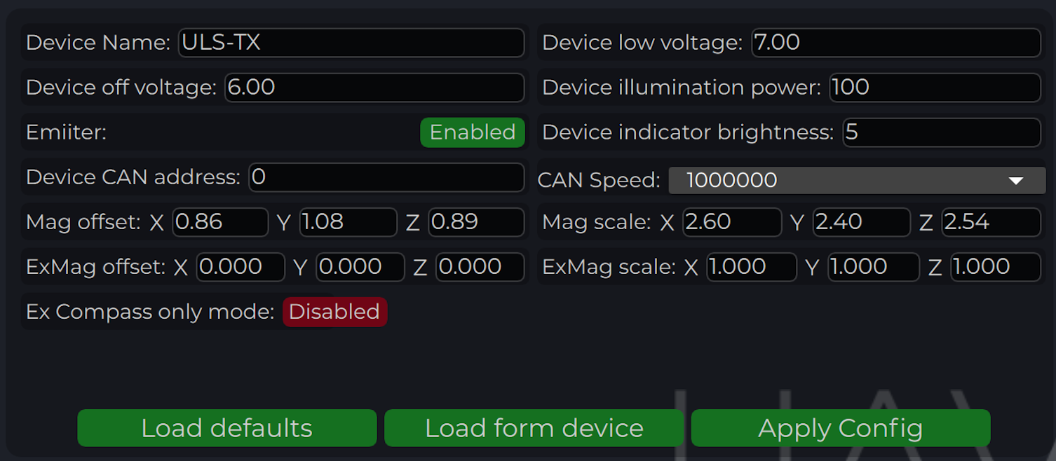
To apply any changes, press “Apply Config” button at the bottom of the field.
Parameter
Description
Device name
Name of the device displayed in main window
Device low voltage
Voltage limit to start indicator flash warning
Device off voltage
Voltage limit to disable IR emitters to prevent battery under discharge
Device illumination power
Emitters power correction (100 for normal operation)
Emitter (enable/disable)
Disable (for configure) or enable emitter
Compass Override (enable/disable) [deg]
Enable in case of module installed on fixed platform. The entered value will be used instead of internal compass data in “Compass mode”. In this way, the transmitter must be turned on the corresponding angle, CW to North.
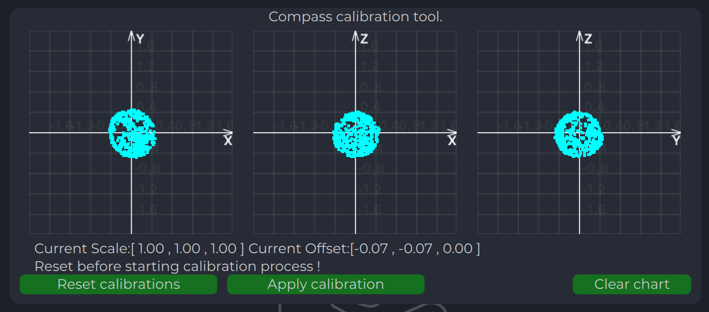
Compass calibration
This compass is used to calculate an absolute heading of the ground unit. This information is transmitted to the Receiver and used to calculate NED coordinates.
To be able to use compass, it needs to be calibrated before.
To calibrate compass:
Press “Reset calibrations”.
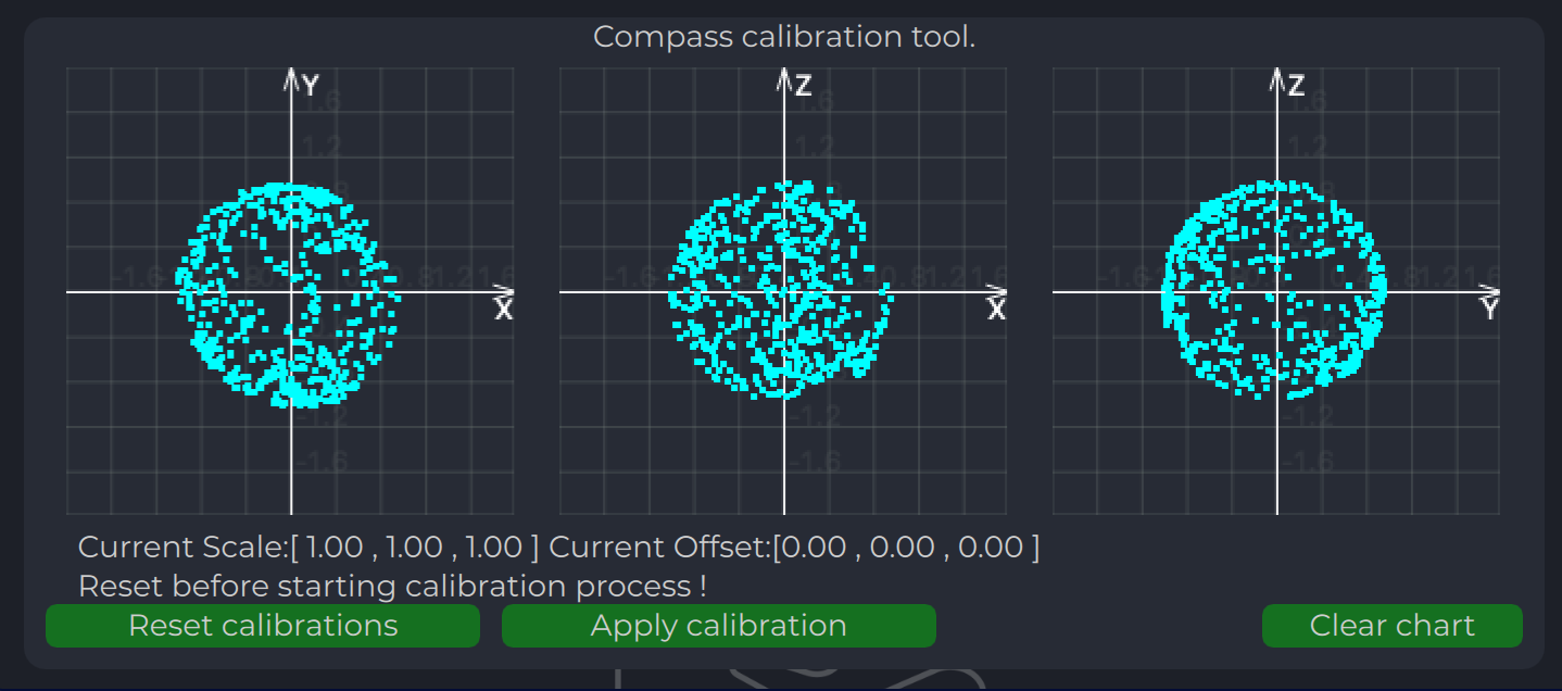
Rotate device in different directions until you get 3 circles on charts (see picture below).
During of calibration you can press “Clear chart” to reset previous compass measurements.
Compass chart before calibration:
Compass chart after calibration:
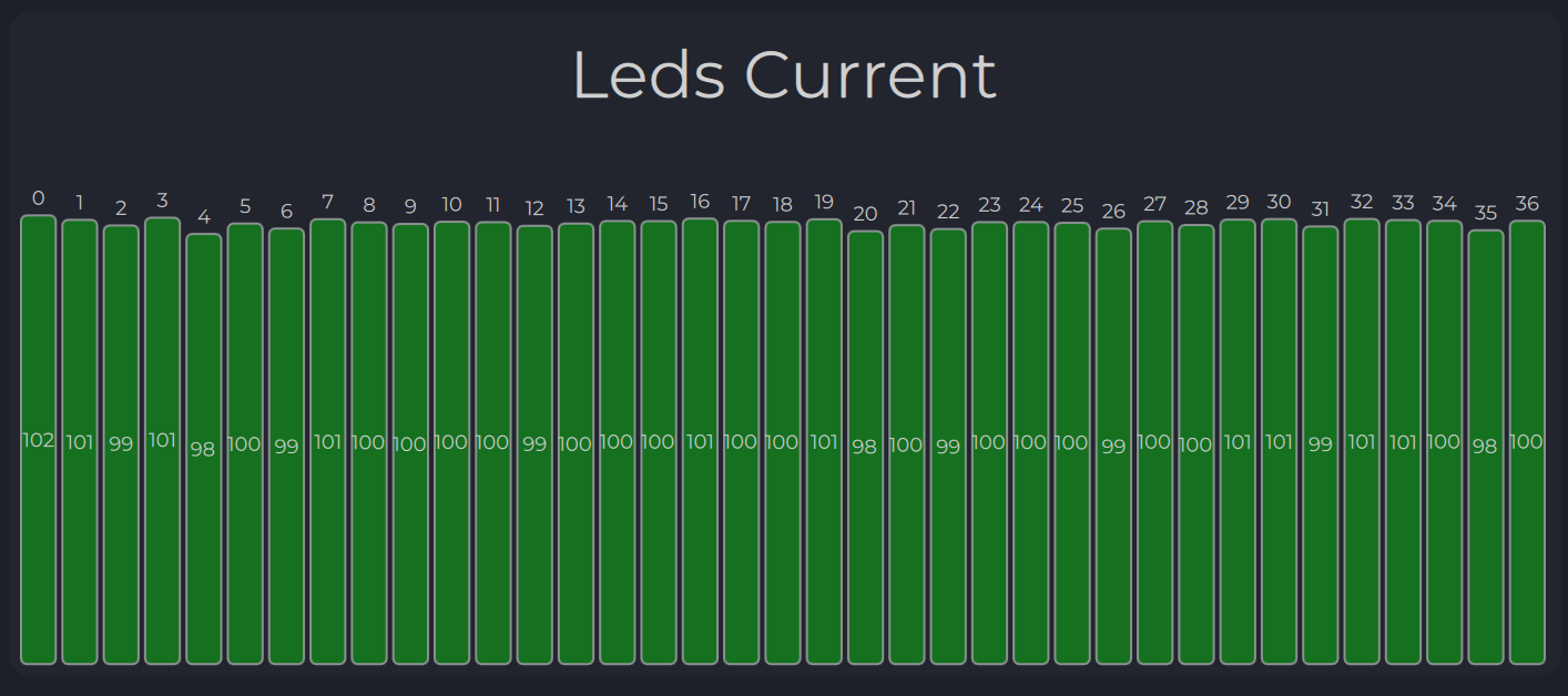
Emitters power indicator
On this field, system shows emitter’s state.
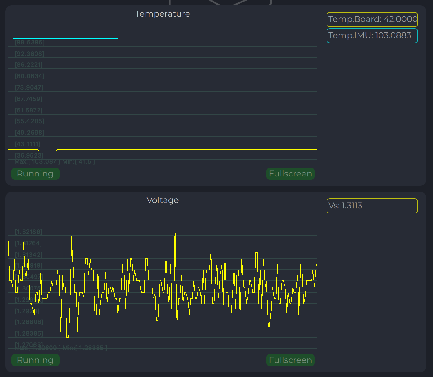
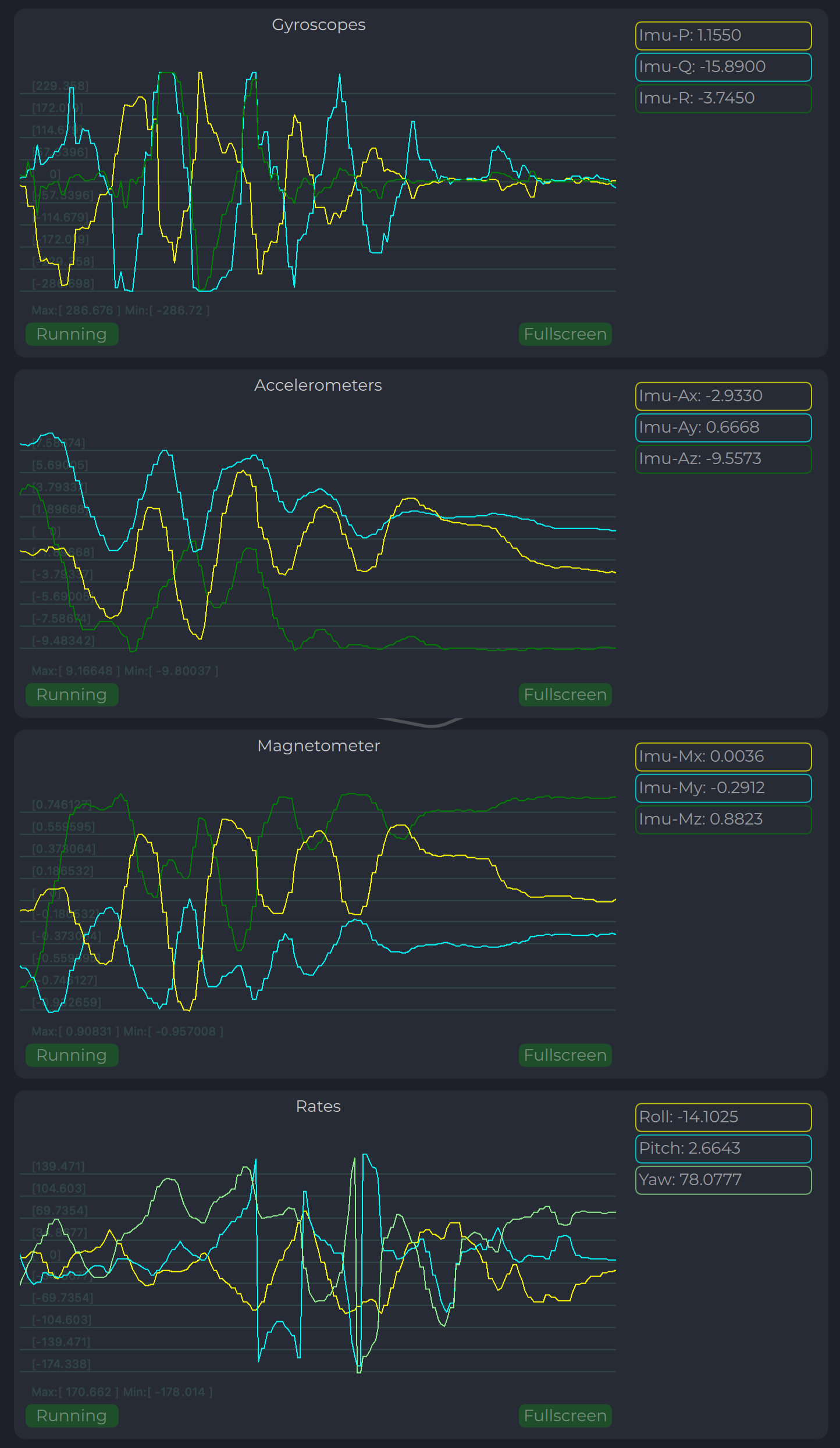
Charts Transmitter
Program display several parameters of the device on charts :
IMU data.
Voltage (not valid when powered from USB).
Temperature data.
Led Indicator
You can check the status of the transmitter looking on the LED indicator on the transmitter.
LED flashes in sequences of colors, so it can flash green-red-off-off or green-off-blue-off.
Flash color
Description
Green
Normal operation.
Orange
Low voltage.
Red
Problem, check device. If it is first in sequence it can be led malfunctions of power voltage below minimum, second for compass fail detect.
Blue
Compass ok and device points to the North (brightness of illumination depends on how precise it is pointed to the North).
On-board unit installation (receiver)
The receiver can be installed both inside and outside the vehicle. However, please note that this version of the system is not equipped with protection against moisture and dust.
The orientation of the receiver does not matter - however, when installing the receiver, care should be taken to ensure line-of-sight conditions between the transmitter and receiver throughout the entire field of view of the receiver (100 deg). The receiver sensor zone is indicated in the figure.
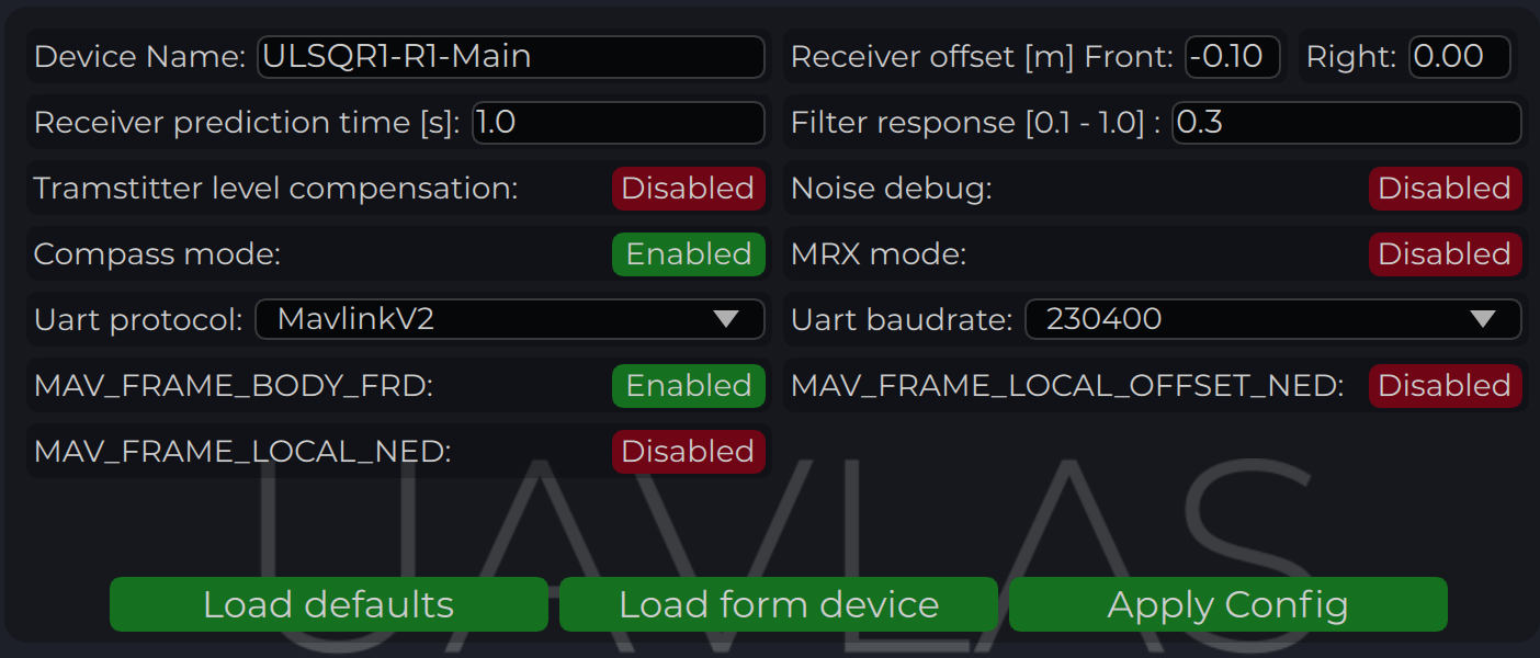
Once the receiver is installed, enter the appropriate receiver offset information into the configuration.
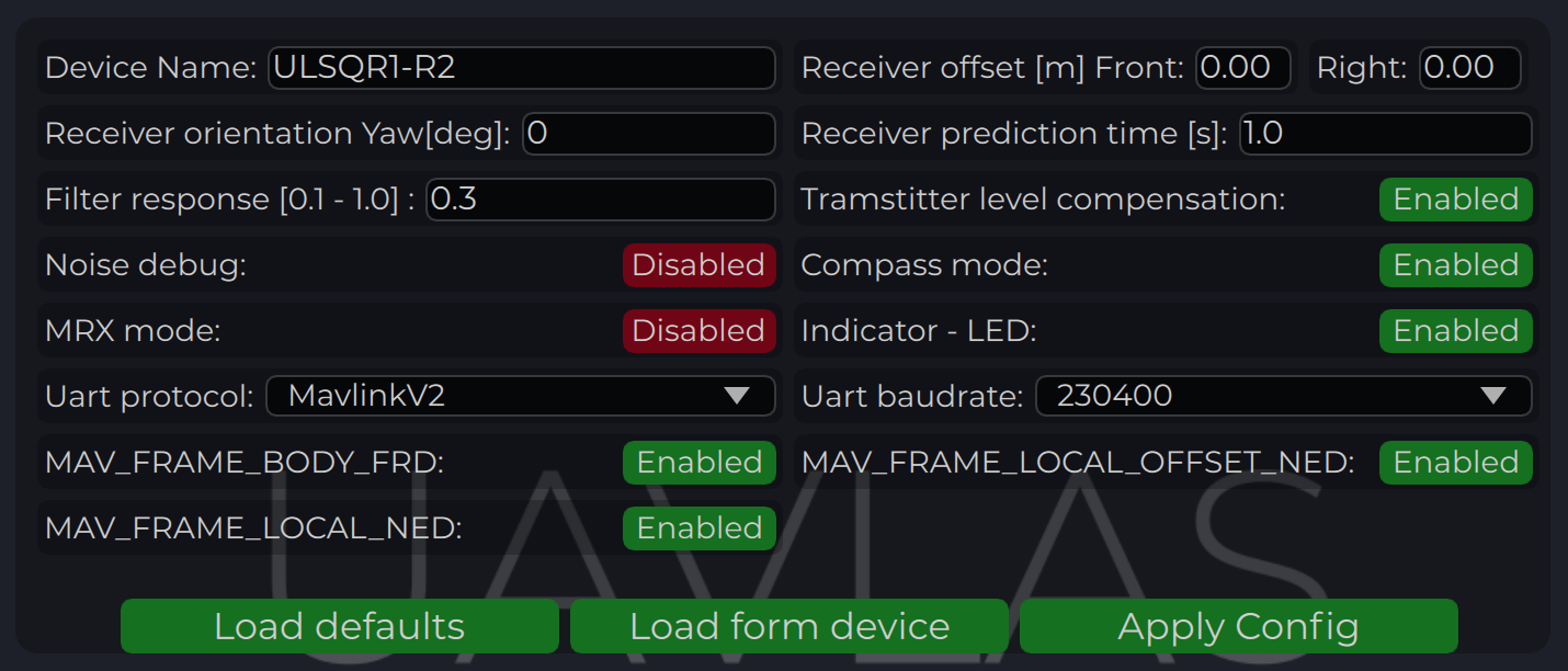
Wiring Receiver Pixhawk 4 autopilot connection using UART
To apply any changes, press “Apply Config” button at the bottom of the field.
Parameter
Description
Device name
Name of the device displayed in main window.
Receiver offset (Front, Right) [m]
Location of receiver in the drone (in meters). This configuration used to calculate drone heading in MultiRX mode.
Receiver orientation YAW [deg] (G2 only)
Receiver orientation settings relative to drone frame It required to set for DACS system.
Receiver prediction time [s]
Prediction time is used to send prediction information of landing position. It is useful to avoid the effect of short terms signal interruptions. Generally, its value can be set from 0.3 up to 1 sec.
Filter response
Set response for internal position filter of receiver. Hi values make lag tame shorter, lower values smooth position information.
Transmitter level compensation
Used to compensate Pan-Tilt rotations of the transmitter. It is used in case of landing on the moving objects.
Noise debug
Use this function to check the noise interference with other devices. In this mode, receiver do not receive the signal from the transmitter, but can capture all the other signals. At the time of the test, transmitter must be switched off, and you can see on Signal Viewer the level of noise and detect what devices around affect the receiver. In general, max level of noise needs to be lower than 0.0025 for Beans B channel. NO OPERATIONS CAN BE PERFORMED IF THIS OPTION IS ENABLED - switch off before the normal use.
Compass mode (disable/enable)
If settings are disabled - receiver will not perform data calculation based on ground compass data. Multi RX mode and (or) compass mode must be enabled to allow the operation.
MRX mode (disable/enable)
If settings are enabled - receiver will use secondary receiver to perform the data calculation. Multi RX mode and (or) compass mode must be enabled to allow the operation.
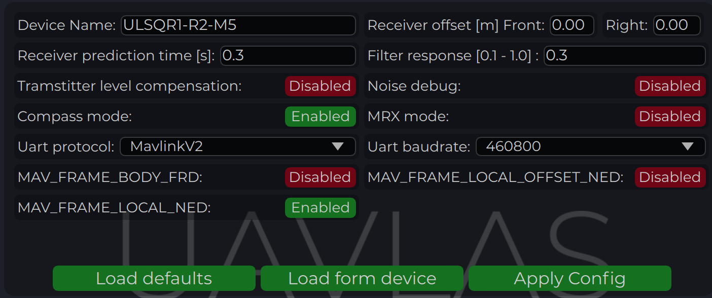
UART Protocol
Select corresponding protocol to communicate with autopilot. If protocol “MavlinkV2” is selected, you can enable the corresponding MAV_FRAME message to be sent to the autopilot (Ardupilot - MAV_FARME_BODY_FRD and PX4 MAV_FRAME_LOCAL_NED for now)
UART baud rate
Select UART communication speed.
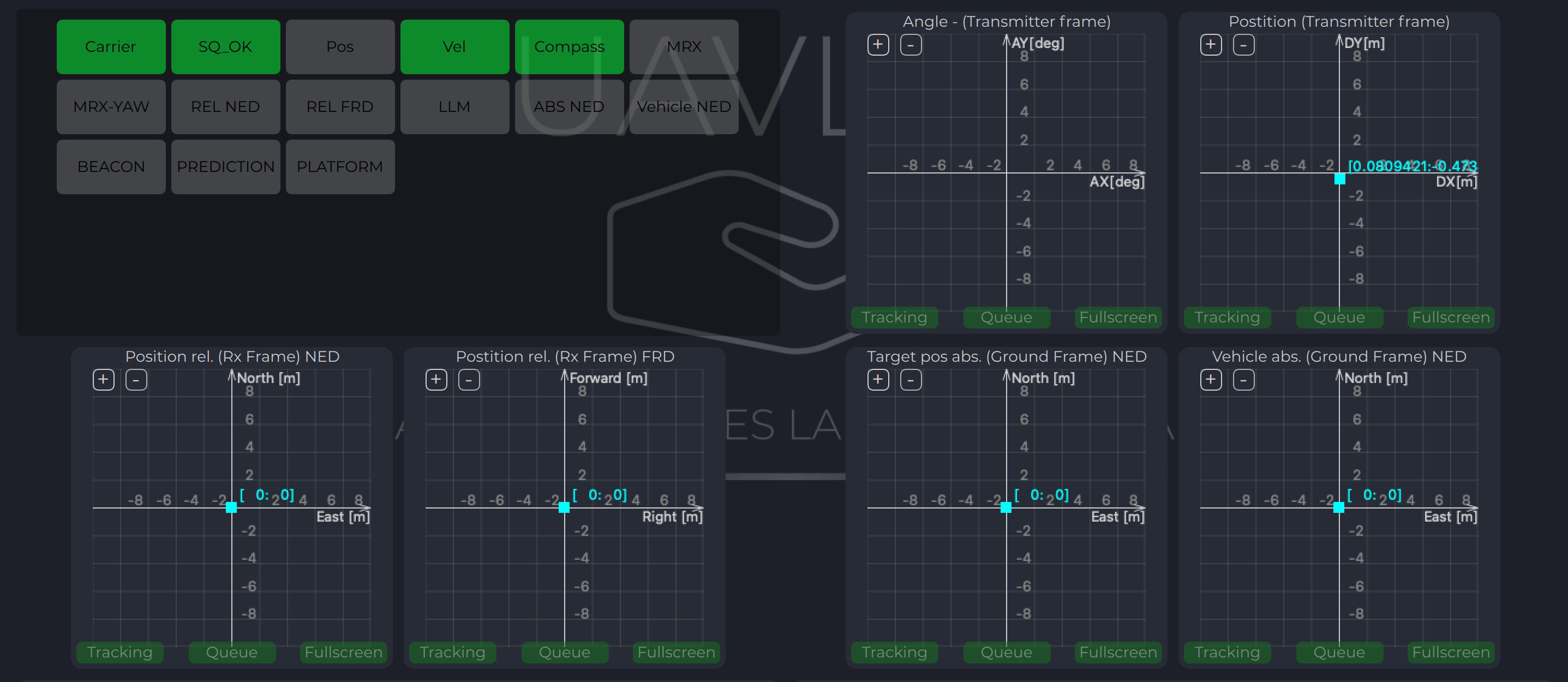
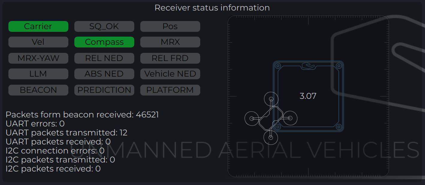
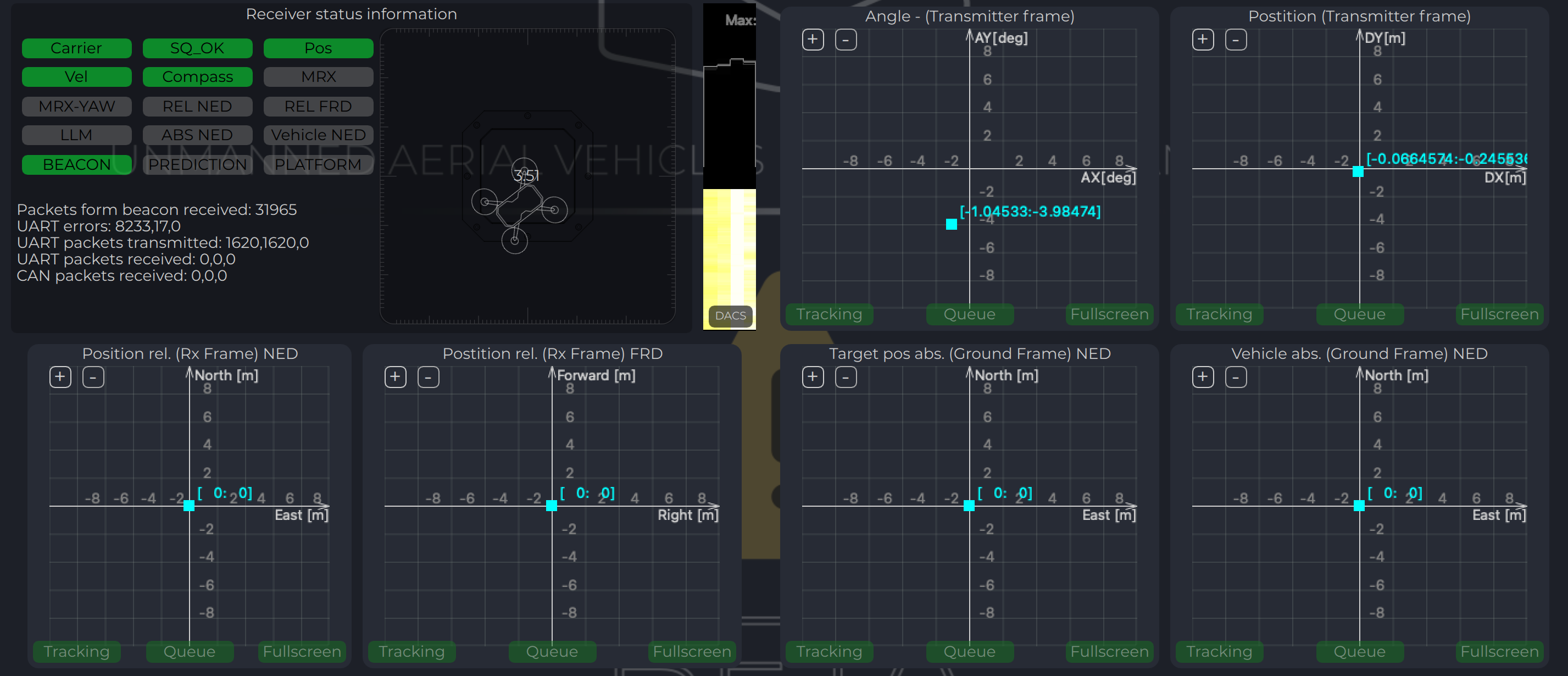
Status Information field
In the status display area, you can check the status of the receiver and visualise the position of the receiver relative to the drone. For XCopter-G2, the YAW orientation of the drone received from the DACS system is displayed.
Parameter
Description
Carrier
The carrier signal from transmitter is detected.
SQ_OK
Signal quality of the carrier is ok.
Pos
RAW sensor position is estimated.
Vel
RAW sensor velocity.
Compass
Ground unit orientation is received.
MRX
Secondary sensor for MRX mode is connected and sending data.
MRX-YAW
Yaw orientation is calculated using MRX.
REL-NED
Relative NED position is calculated.
REL-FRD
Relative FRD position is calculated.
LLM
Lat Lon Msl position is available (reserved for future options).
ABS-NED
Absolute position of transmitter is available.
VEHICLE-NED
Absolute position of vehicle is provided by the autopilot (used to calculate ABS position data).
BEACON
Indicate System Ok state.
PREDICTION
Indicate when system uses predicted information for the calculation.
PLATFORM
Position of landing platform is provided by third party devices.
Setup MRX mode
This option enables to use data from two receivers to calculate position. It allows calculating receiver yaw orientation using triangular method. In this mode, compass data (on ground and on board) is not affecting the position estimation, so it is more durable way to land. In this mode the maximum distance is limited by 10 m and at altitude above, it will use compass mode.
To set up and check MRX mode do the following:
Connect receivers on board with CAN BUS (See MRX Wiring).
Configure “Receiver offset” for both receivers.
Configure “Receiver orientation YAW” for both receivers (XCopter-G2).
Enable option “MRX mode”.
After set up, hover the drone above the transmitter (1 m - 2 m) and check that TDistance and Distance values (On charts “Distances”) are the same (+/- 20%).
Correct “Receiver offset” option in case of TDistance and Distance are not approximately the same. Increasing position between receivers increases TDistace and backwards.
Rotate Drove over transmitter (1 m - 2 m) and check the value of the MRX-YAW on chart “GU Orientation”. It needs to be corresponding to the heading of the drone relatively to the transmitter.
Warning
Warning: check “Remote IMU”, “Filter smoothness”, “Receiver sensitivity”, “Receiver prediction time”, setting MUST be equal to ALL the receivers on the vehicle.
Note
Please note, you can connect receiver directly to PC using USB pins. It will make the set up and testing receiver much easier. See pinouts info for details
DACS
The Distance and Azimuth Correction System allows you to determine the orientation of the receiver relative to the transmitter within +/-90 degrees.
This system uses 4 additional LEDs on the transmitter. The presence of this system allows you to clarify the orientation of the receiver with a compass or using MRX technology. In case of using MRX technology, DACS tracks the drone’s rotation. Thus, for a system that works in MRX mode it is enough to get the orientation once and in the future, provided it is in the area of the transmitter, the receiver will track the position of the drone even if approaching the transmitter one of the receivers will be out of range and MRX data will be unavailable.
Warning
Warning: It is Very important to configure “Receiver orientation YAW” for both receivers for DACS. You can check orientation settings by comparing real drone orientation with picture on “Status Information Field”
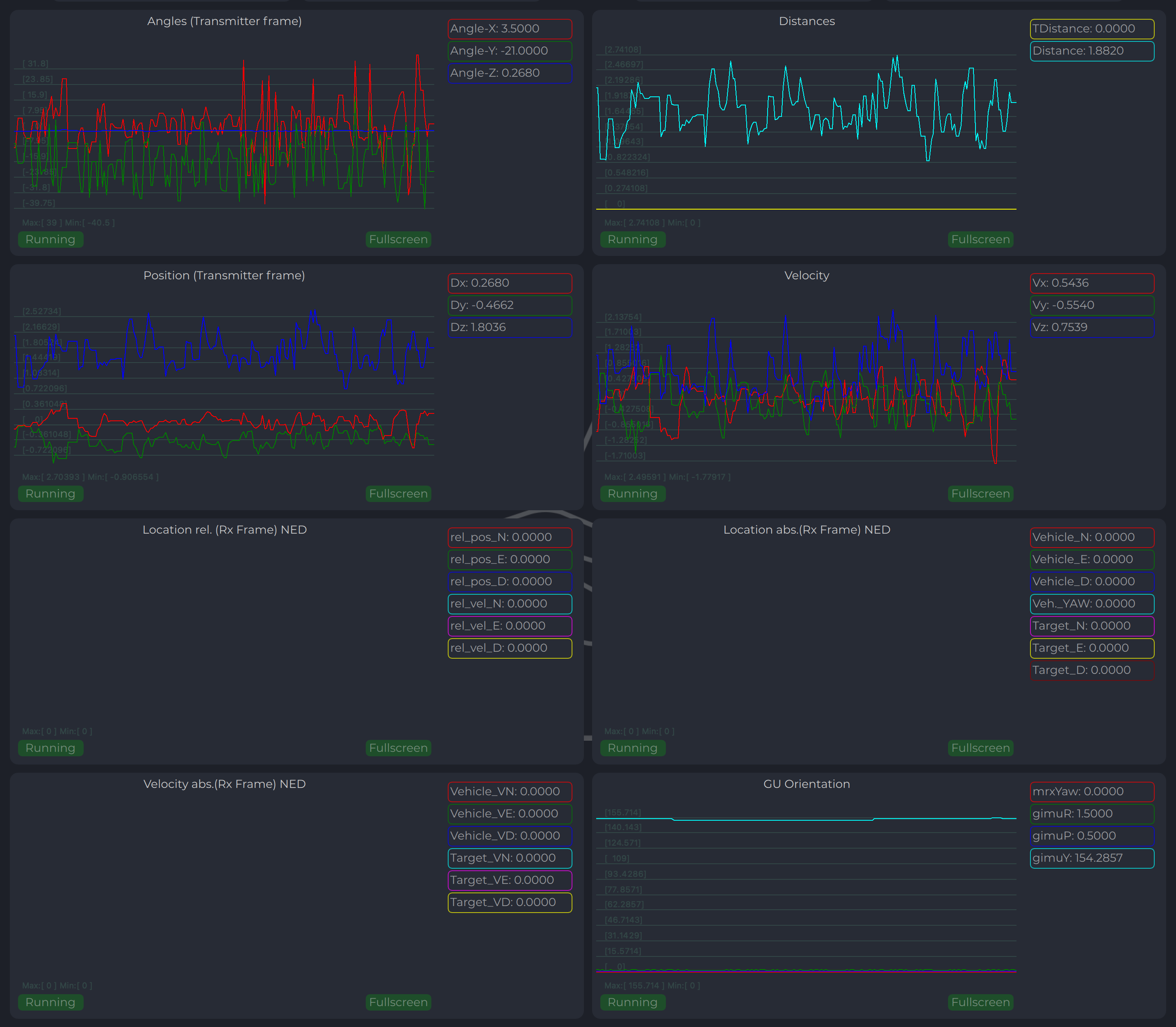
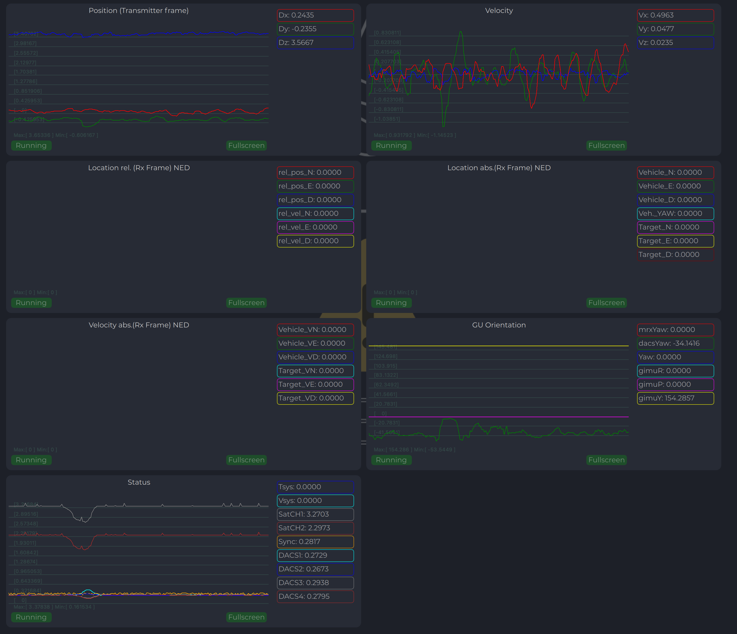
Receiver Charts
Program display several parameters of the device on charts :
Angles, Positions in different coordinate systems
Distance
Vehicle information (position and velocity)
Data from Transmitters IMU.
3.3.1 - Ardupilot
Integration instructions for Ardupilot based systems.
Current version of the system can use MavlinkV2 protocol to communicate with Ardupilot autopilots (for now it supports MAV_FRAME_BODY_FRD).
Example of receiver configuration:
Autopilot configuration
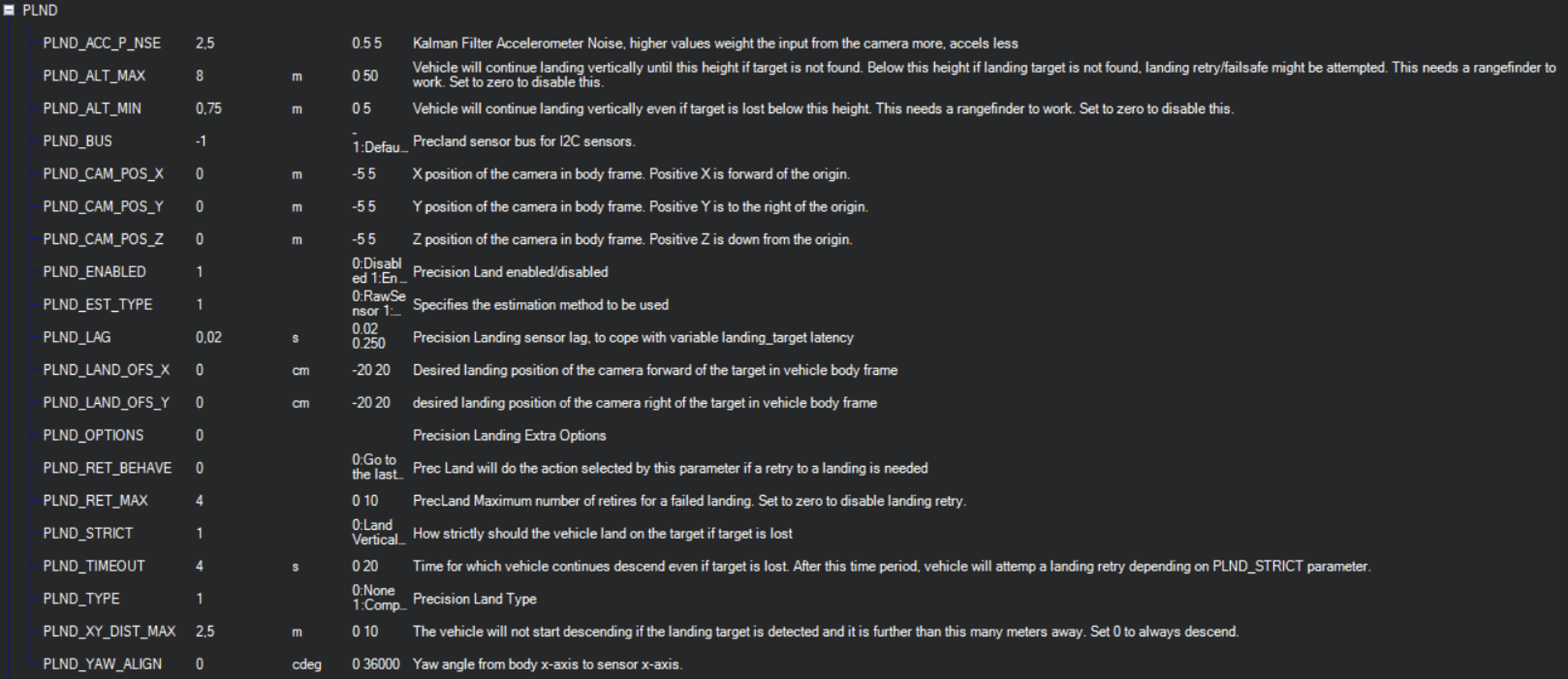
Setup PLND section
Param
Value
Comment
PLND_ENABLED
1
Enable precision landing module
PLND_TYPE
1
Use type = 1 to enable UAVLAS sensor over Companion computer driver
All other parameters in PLND section defaults or use accordingly to your vehicle set up requirements.
On a picture example configuration provided.
Note
It is recommended to test several options of Kalman filter during the test flights (or switch it off) to achieve the best performance.
Set up serial communication in SERIALx Section.
Param
Value
Comment
SERIAL2_BAUD
230
Select baud rate - it needs to be same as in receiver’s configuration.
SERIAL2_OPTIONS
0
Default
SERIAL2_PROTOCOL
2
MAVlink2 protocol support.
Set up serial communication messages in SRx Section.
Sensor requires some data from autopilot to work in different modes.
Param
Value
Comment
SR2_EXTRA1 (or MAV2_EXTRA1)
20
Stream Attitude information (20Hz) (YAW Orientation is required for sensor in compass mode)
SR2_POSITION (or MAV2_POSITION)
20
Optional - Stream Vehicle position (20Hz) (LOCAL_POSITION_NED is required for sensor to provide LOCAL position for the target)
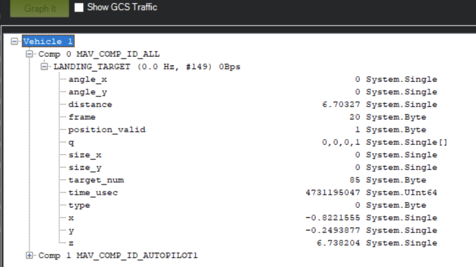
Check setup.
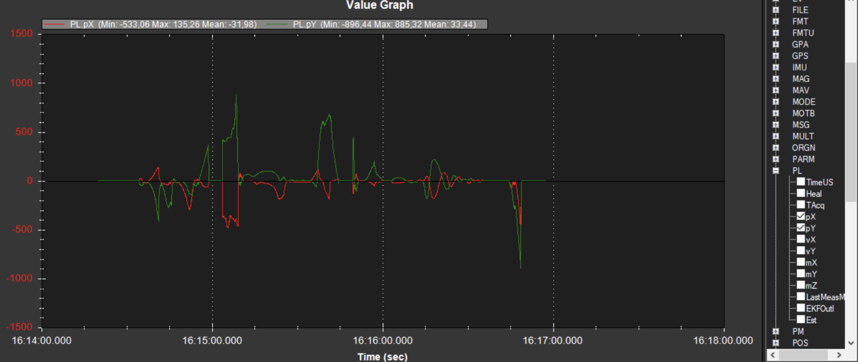
If all settings are done correct, autopilot has GPS data and receiver in the field of view of the transmitter, you can find LANDING_TARGET message in mavlink inspector (a screenshot from Mission Planner)
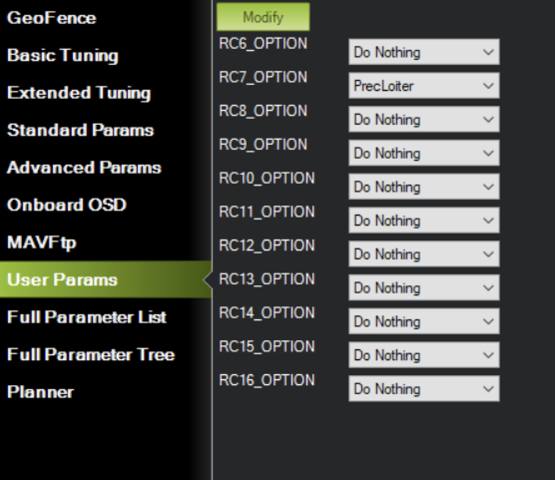
Setup Precision loiter mode.
To enable precision loiter mode you need attach any unused switch to PrecLoiter option see picture below:
Try to use this switch and you must get messages: “PrecLoiter: LOW” and “PrecLoiter: HIGH”
After test flight above target check telemetry - you will find PL data contains offsets form landing target.
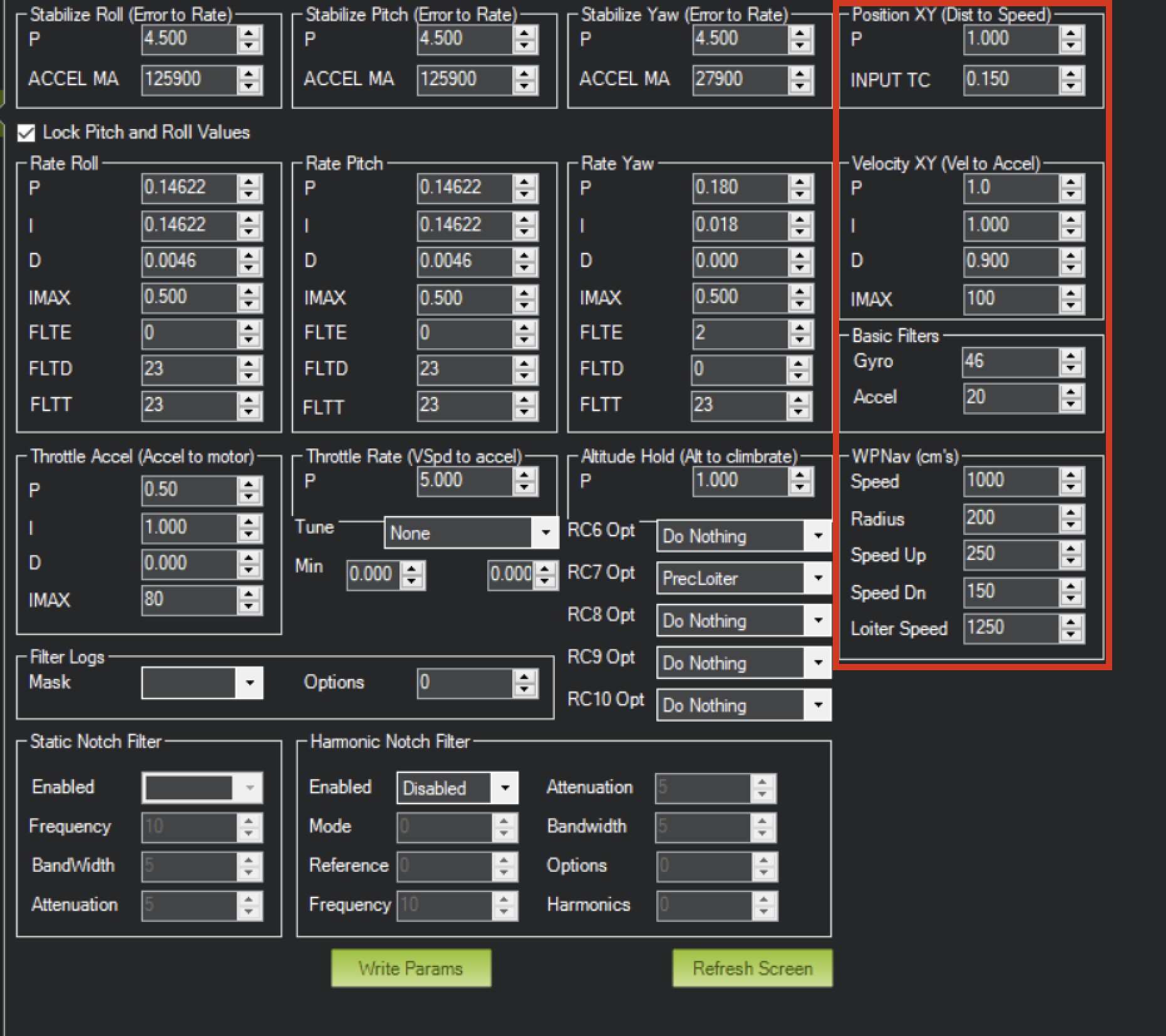
PID tuning
In case of oscillations and other issues at landing stage, pls, check PID parameters of Ardupilot.
It is recommended to check the Position XY, Velocity XY and Loiter speed parameters in “Extended tuning” section to achieve the best performance.
Note
For example, settings Velocity XY P = 0.8, I = 0.2, and D = 0.6 works well for some of our customers
Note
It recommended to start testing PIDs and precision system performance in “Precision Loiter” mode. I use some algorithms and settings in precision landing.
For additional information, see Ardupilot manual.
Troubleshooting
Before of all check:
You are using lates version od ULS-Tools, lates firmware on USL-XCOPTER transmitter and receiver, and latest Ardupilot firmware.
ULS-XCopter transmitter are switched on and receiver in field of view of transmitter.
Red light on receiver flashes fast ( > 5 times per second ). If it flash 2 times per sec it mean that transmitter not switched on, or not in field of view. If it not flash - check power.
Check Serial setting on AP params and on receiver be sure you are set EXTRA params for corresponding serial port on AP.
It is recommended to download the latest version of the ULSTools software (See download page for details)
It is recommended to connect all sensor to the PC and update the firmware for all UAVLAS devices in the system. (See ULSTools page for details)
Current version of the system can use MavlinkV2 protocol to communicate with PX4 autopilots (for now it supports MAV_FRAME_LOCAL_NED).
Example of receiver configuration:
Download Firmware for PX4
UAVLAS device is working using a standard Mavlink messages protocol.
But in PX4 v1.13 and lower there are some issues related to precision landing capability, so it is required to flash the patched firmware file.
Important
Custom firmware for PX4 stock is only required if you prefer to use versions below 1.14. Otherwise, use the official PX4 firmware. Custom PX4 builds for UAVLAS system will be deprecated soon. Please note that PX4 version v1.14.0-beta2 is currently available for testing, which is fully compatible with ULS-XCOPTER, we recommend that you use it for your tests. See PX4 Github repo.
Values are provided as example (in our case, Pixhawk4-mini AP)
PX4 Parameter
Value
MAV_1_CONFIG
TELEM/SERIAL4 (require reboot to set next params)
MAV_1_FORWARD
Enabled.
MAV_1_MODE
Onboard.
SER_TEL4_BAUD
460800_8N1 (It needs to be corresponding to the setting of UART in Receiver ULS-QR1-R1 connected to PX4 AP)
Running and testing
After configuration and wiring, power up drone and transmitter.
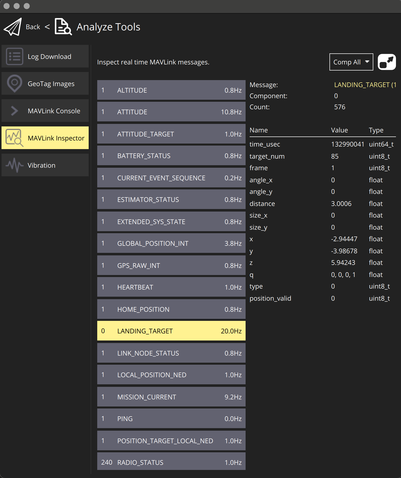
On QGround control, go “Analyze Tools” -> MAVLINK Inspector.
Check LANDING_TARGET MAVLINK message
IMPORTANT:
LANDING_TARGET may be unavailable in case of connection over USB. So, use telemetry channel (uart modem etc.) to connect drone to the QGroundControl.
In case the vehicle provide LOCAL_POSITION_NED message to UAVLAS system, and it hovers over beacon, you get “position_valid = 1” in LANDING_TARGET
To perform precision landing, you need to create a flight plan and enable Precision Landing option on the landing point.
Have a good flights !
3.4 - Troubleshooting
Have questions or some troubles with integration or using of the UL-XCopter? Here you can find the answers for the common questions.
No Mavlink messages
Check wiring.
Check AP (autopilot) serial baud rate.
Check AP (autopilot) serial protocol config.
Check Mavlink messages Setup form AP to the receiver.
Check the receiver frame configuration.
Check the transmitter power.
Circular motions during landing
Check compass calibration on ground unit.
Check Compass calibration on AP.
Check magnetic interference on ground.
Use compass override mode to debug landing.
Check precision landing PID settings.
The landing is not precise enough
Check the position control PID settings of AP.
For Ardupilot check Kalman filter settings.
Check filter smoothness param on receiver.
Check trajectory Jerk settings on AP.
If nothing works:
Update firmware of UAVLAS equipments and reset to default settings - repeat setup. Update autopilot firmware, reset autopilot settings to default, perform autopilot calibrations and settings from the beginning. Contact support.
4 - ULS-ProCopter
Basic information about the product line.
UAVLAS is develop a ruggedized version of the ULS-XCopter to meet the needs of customers who require a more robust system at an affordable price.
Achieving an IP67 dust and waterproof rating for transmitter ensures that the device is well-suited for use in harsh environments, which can be particularly important in industrial application. It will also provide additional reassurance to users working in adverse weather conditions.
In addition to dust and moisture protection, the system (as well as the rest of our equipment) remains functional in bright sunlight and at night.
In addition, the system can be equipped with a heating system to ensure operation in heavy snow conditions.
Also, this type of system has a wide viewing angle (up to 100 degrees) for both transmitter and receiver. This allows the system to work confidently both at height and up to full touchdown
4.1 - Application
What is the best application for this series of systems? How to use it properly?
Landing on platform, emergency landing
To perform an accurate landing on the platform, it is necessary to mark out the landing area transmitter. Due to its small size, it can be easily placed even on a small platform. In case of an emergency landing, the transmitter can simply be placed on any surface and connected to a power source.
The receiver must be mounted on board of the aircraft in a line of sight with the transmitter. It is desirable to place the receiver closer to the center of the drone, but if it is not possible to place the receiver directly in the landing center area, the offset can be eliminated by adjusting the receiver accordingly.
For more information, see the integration section.
Landing on the elevated platforms
Since the system calculates the distance to the landing point by itself, there is no need to use additional tools to ensure landing on a float plane that is at a significant elevation from the surrounding environment. This will be useful when landing on masts, tall structures, large vehicles, etc. No additional adjustments are required in this case.
Landing on balcony
A special case of landing is landing on a platform accessible only from one side. For example, balconies. In this case, it is not possible to make a vertical landing. With our system, however, you can easily select the landing angle simply by orienting the transmitter in the desired direction. In this case, the receiver will continuously transmit updated data about the position of the landing site so that the trajectory of the aircraft will not be vertical. Also, in this mode, you can dynamically control the position of the drone by changing the inclination of the transmitting beacon. Please note that this function can be disabled in the receiver settings and then the landing will always be vertical regardless of the transmitter tilt (e.g. if you are landing on a moving platform).
Wireless charging stations and contactless delivery
The system can be used not only to provide a landing, but also to realize a precise hovering over the desired point. This is useful for e.g. for wireless charging systems - in which the drone is charged while in vision, or for e.g. in cases when the cargo is delivered without contact (dropped). It should be noted that our system provides not only the horizontal position shift, but also the altitude. This allows accurate positioning not only in the horizontal plane, but also in height - this is very important for wireless charging and contactless delivery.
4.2 - Specification
Detailed product specification information
Common specification:
Parameter
ULS-ProCopter-G1
Distance range m.:
0.1 - 20.0
Working angle (deg):
>100
Data update frequency (Hz):
20
Receiver (on board unit):
Parameter
ULS-ProCopter-G1
Field of view (deg):
100
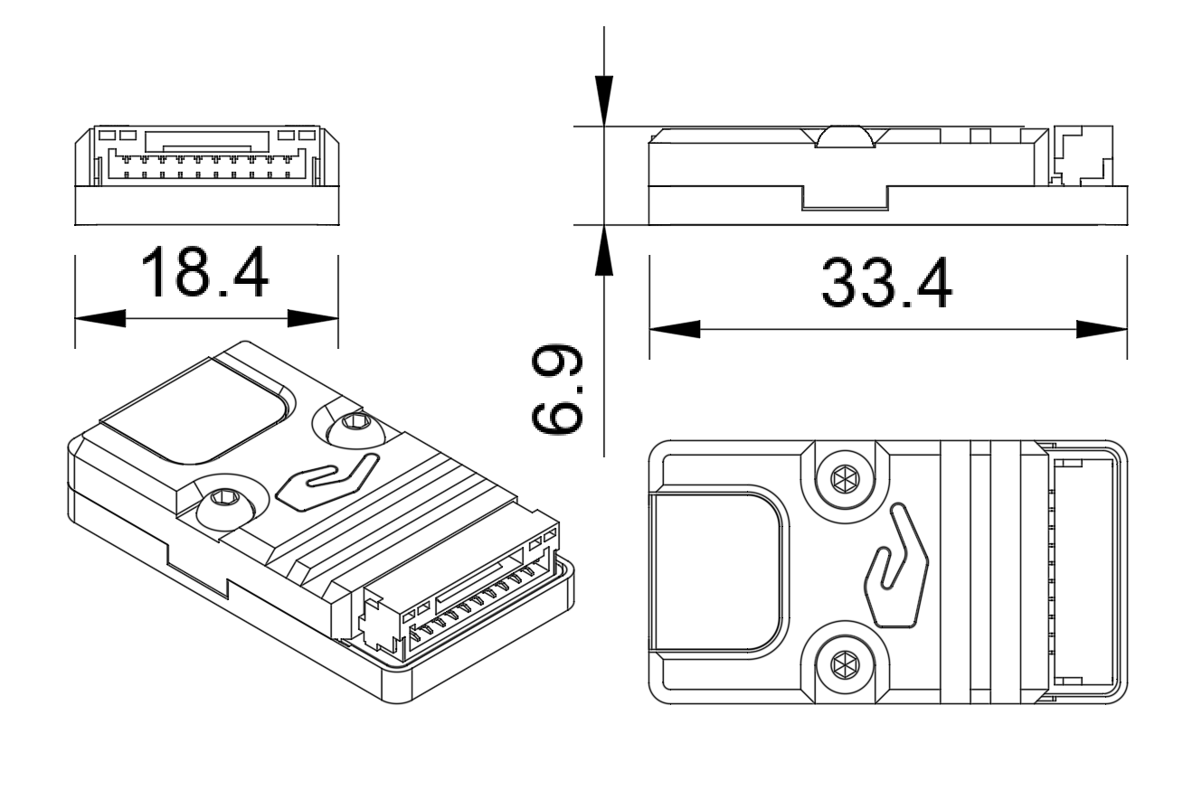
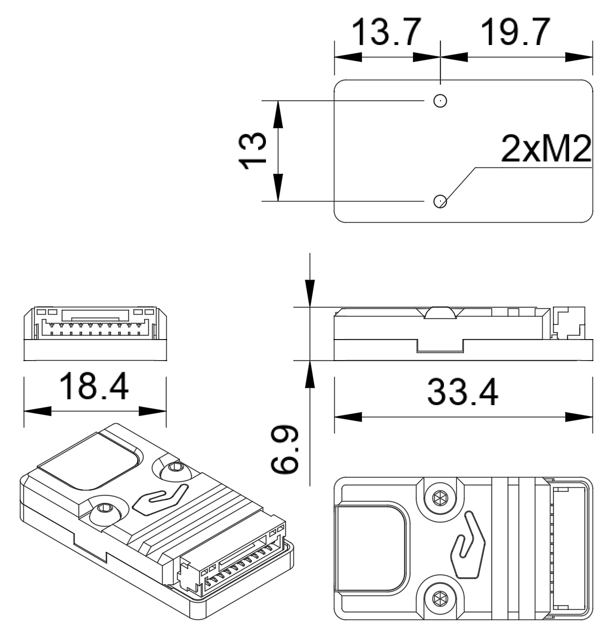
Dimensions mm :
18.4 x 33.4 x 6.9
Weight g.:
10
Power Consumption (W):
0.3
Voltage supply (V):
5.0
Interfaces:
USB, CAN, UART
Transmitter (on ground)
Parameter
ULS-ProCopter-G1
Field of emitting (deg):
>100
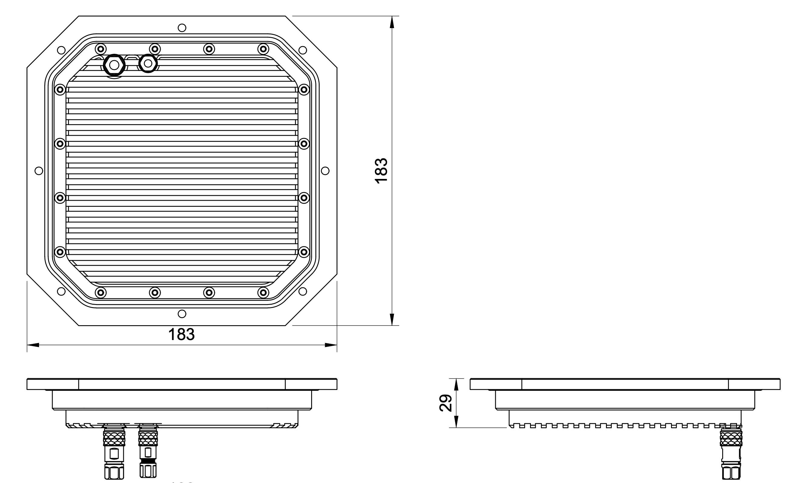
Dimensions mm. :
183 x 183 x 29
Weight g.:
1200
Power Consumption (W):
2.1
Voltage supply (V):
12.0 - 27.0
Interfaces :
USB, CAN, UART
System Measurement Accuracy Diagram
Mechanical dimensions
ULS-ProCopter receiver
ULS-ProCopter transmitter
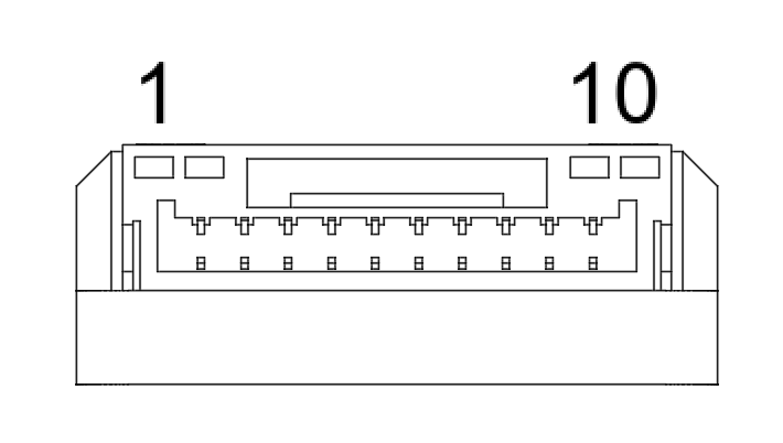
Receiver pinout
JX1 - External power and control
Pin number
Description
1
+5V Input
2
UART RX
3
UART TX
4
CAN H
5
CAN L
6
USB D-
7
USB D+
8
UART2 RX
9
UART2 TX
10
GND
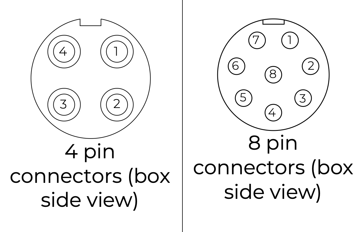
Transmitter pinout
8-pin connector - Main connector
Pin number
Description
1
Vcc Input (+12.0V..+27V)
2
CAN2 H
3
CAN2 L
4
UART TX
5
UART RX
6
USB D-
7
USB D+
8
GND
4 pin connector - Submodules connection
Pin number
Description
1
+5V Output
2
CAN1 H
3
CAN1 L
5
GND
4.3 - Integration
Technical instructions - how to integrate and set up the system.
Ground unit installation (transmitter)
The device must be installed on a clean surface to avoid any obstacles.
The device must be installed in an open area. There must be no obstacles in the radiation field of the transmitting device. If possible, avoid installing the system near vertical surfaces that can strongly reflect infrared radiation.
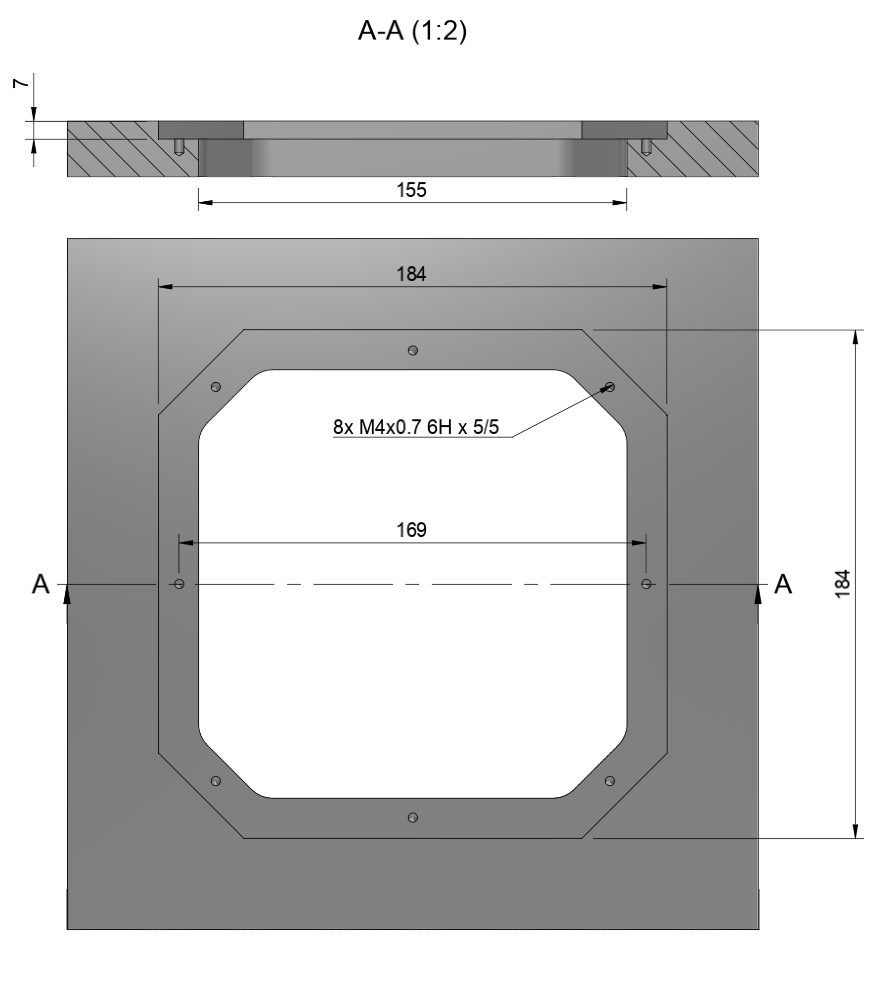
Device developed to be installed in panel and bolted with M4 screw.
All customers get 3d model of system and cuted panel as reference to make integration process more simple.
Panel cut-out drawing.
Wiring Transmitter
The transmitter only requires power to operate. The transmitter can be powered either via USB-C or via a 6-pin connector located nearby.
Warning: ULS-ProCopter on beta stage now pls use Beta version of ULS-Tools for configuration and firmware update. You can download it here
Note
To apply any changes, press “Apply Config” button at the bottom of the field.
Parameter
Description
Device name
Name of the device displayed in main window
Device low voltage
Voltage limit to start indicator flash warning
Device off voltage
Voltage limit to disable IR emitters to prevent battery under discharge
Device illumination power
Emitters power correction (100 for normal operation)
Emitter (enable/disable)
Disable (for configure) or enable emitter
Device Indicator Brightness
Adjust transmitter RGB led indicator brightness
Device CAN address/speed
Setup extenal CAN interface parameters
Compass Override (enable/disable) [deg]
Enable in case of module installed on fixed platform. The entered value will be used instead of internal compass data in “Compass mode”. In this way, the transmitter must be turned on the corresponding angle, CW to North.
Mag(ExMag) offset/scale
Calibration parameters for internal/external magnetometer
ExCompass mode only
If enabled - system will not use internal compass. If external compass data unavialible system generate erorr. If idsbled internal compass will be used if External magnetometer unavilible
Compass calibration
This compass is used to calculate an absolute heading of the ground unit. This information is transmitted to the Receiver and used to calculate NED coordinates.
To be able to use compass, it needs to be calibrated before.
To calibrate compass:
Press “Reset calibrations”.
Rotate device in different directions until you get 3 circles on charts (see picture below).
During of calibration you can press “Clear chart” to reset previous compass measurements.
Compass chart before calibration:
Compass chart after calibration:
Charts Transmitter
Program display several parameters of the device on charts :
IMU data.
Voltage (not valid when powered from USB).
Temperature data.
Led Indicator
You can check the status of the transmitter looking on the LED indicator on the transmitter.
LED flashes in sequences of colors, so it can flash green-red-off-off or green-off-blue-off.
Flash color
Description
Green
Normal operation.
Orange
Low voltage.
Red
Problem, check device. If it is first in sequence it can be led malfunctions of power voltage below minimum, second for compass fail detect.
Blue
Compass ok and device points to the North (brightness of illumination depends on how precise it is pointed to the North).
On-board unit installation (receiver)
The receiver can be installed both inside and outside the vehicle. However, please note that this version of the system is not equipped with protection against moisture and dust.
The orientation of the receiver does not matter - however, when installing the receiver, care should be taken to ensure line-of-sight conditions between the transmitter and receiver throughout the entire field of view of the receiver (100 deg). The receiver sensor zone is indicated in the figure.
Once the receiver is installed, enter the appropriate receiver offset information into the configuration.
Wiring Receiver Pixhawk 4 autopilot connection using UART
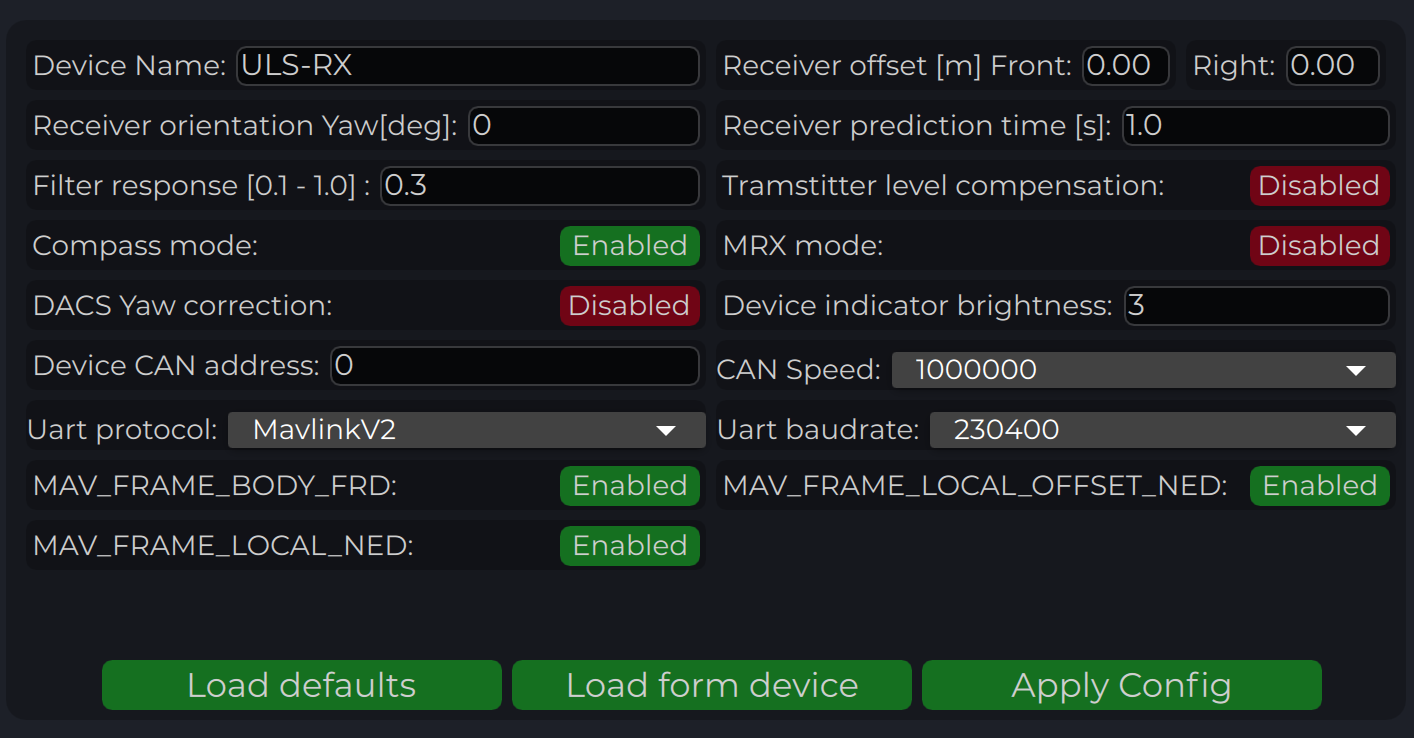
To apply any changes, press “Apply Config” button at the bottom of the field.
Parameter
Description
Device name
Name of the device displayed in main window.
Receiver offset (Front, Right) [m]
Location of receiver in the drone (in meters). This configuration used to calculate drone heading in MultiRX mode.
Receiver orientation YAW [deg] (G2 only)
Receiver orientation settings relative to drone frame It required to set for DACS system.
Receiver prediction time [s]
Prediction time is used to send prediction information of landing position. It is useful to avoid the effect of short terms signal interruptions. Generally, its value can be set from 0.3 up to 1 sec.
Filter response
Set response for internal position filter of receiver. Hi values make lag tame shorter, lower values smooth position information.
Transmitter level compensation
Used to compensate Pan-Tilt rotations of the transmitter. It is used in case of landing on the moving objects.
Noise debug
Use this function to check the noise interference with other devices. In this mode, receiver do not receive the signal from the transmitter, but can capture all the other signals. At the time of the test, transmitter must be switched off, and you can see on Signal Viewer the level of noise and detect what devices around affect the receiver. In general, max level of noise needs to be lower than 0.0025 for Beans B channel. NO OPERATIONS CAN BE PERFORMED IF THIS OPTION IS ENABLED - switch off before the normal use.
Compass mode (disable/enable)
If settings are disabled - receiver will not perform data calculation based on ground compass data. Multi RX mode and (or) compass mode must be enabled to allow the operation.
MRX mode (disable/enable)
If settings are enabled - receiver will use secondary receiver to perform the data calculation. Multi RX mode and (or) compass mode must be enabled to allow the operation.
Device Indicator Brightness
Adjust transmitter led indicator brightness
Device CAN address/speed
Setup extenal CAN interface parameters
DACS yaw corewction
Disable or Enable DACS system.
UART Protocol
Select corresponding protocol to communicate with autopilot. If protocol “MavlinkV2” is selected, you can enable the corresponding MAV_FRAME message to be sent to the autopilot (Ardupilot - MAV_FARME_BODY_FRD and PX4 MAV_FRAME_LOCAL_NED for now)
UART baud rate
Select UART communication speed.
Status Information field
In the status display area, you can check the status of the receiver and visualise the position of the receiver relative to the drone. For XCopter-G2, the YAW orientation of the drone received from the DACS system is displayed.
Parameter
Description
Carrier
The carrier signal from transmitter is detected.
SQ_OK
Signal quality of the carrier is ok.
Pos
RAW sensor position is estimated.
Vel
RAW sensor velocity.
Compass
Ground unit orientation is received.
MRX
Secondary sensor for MRX mode is connected and sending data.
MRX-YAW
Yaw orientation is calculated using MRX.
REL-NED
Relative NED position is calculated.
REL-FRD
Relative FRD position is calculated.
LLM
Lat Lon Msl position is available (reserved for future options).
ABS-NED
Absolute position of transmitter is available.
VEHICLE-NED
Absolute position of vehicle is provided by the autopilot (used to calculate ABS position data).
BEACON
Indicate System Ok state.
PREDICTION
Indicate when system uses predicted information for the calculation.
PLATFORM
Position of landing platform is provided by third party devices.
Setup MRX mode
This option enables to use data from two receivers to calculate position. It allows calculating receiver yaw orientation using triangular method. In this mode, compass data (on ground and on board) is not affecting the position estimation, so it is more durable way to land. In this mode the maximum distance is limited by 10 m and at altitude above, it will use compass mode.
To set up and check MRX mode do the following:
Connect receivers on board with CAN BUS (See MRX Wiring).
Configure “Receiver offset” for both receivers.
Configure “Receiver orientation YAW” for both receivers (XCopter-G2).
Enable option “MRX mode”.
After set up, hover the drone above the transmitter (1 m - 2 m) and check that TDistance and Distance values (On charts “Distances”) are the same (+/- 20%).
Correct “Receiver offset” option in case of TDistance and Distance are not approximately the same. Increasing position between receivers increases TDistace and backwards.
Rotate Drove over transmitter (1 m - 2 m) and check the value of the MRX-YAW on chart “GU Orientation”. It needs to be corresponding to the heading of the drone relatively to the transmitter.
Warning
Warning: check “Remote IMU”, “Filter smoothness”, “Receiver sensitivity”, “Receiver prediction time”, setting MUST be equal to ALL the receivers on the vehicle.
Note
Please note, you can connect receiver directly to PC using USB pins. It will make the set up and testing receiver much easier. See pinouts info for details
DACS
The Distance and Azimuth Correction System allows you to determine the orientation of the receiver relative to the transmitter within +/-90 degrees.
This system uses 4 additional LEDs on the transmitter. The presence of this system allows you to clarify the orientation of the receiver with a compass or using MRX technology. In case of using MRX technology, DACS tracks the drone’s rotation. Thus, for a system that works in MRX mode it is enough to get the orientation once and in the future, provided it is in the area of the transmitter, the receiver will track the position of the drone even if approaching the transmitter one of the receivers will be out of range and MRX data will be unavailable.
Warning
Warning: It is Very important to configure “Receiver orientation YAW” for both receivers for DACS. You can check orientation settings by comparing real drone orientation with picture on “Status Information Field”
Receiver Charts
Program display several parameters of the device on charts :
Angles, Positions in different coordinate systems
Distance
Vehicle information (position and velocity)
Data from Transmitters IMU.
4.3.1 - Ardupilot
Integration instructions for Ardupilot based systems.
Current version of the system can use MavlinkV2 protocol to communicate with Ardupilot autopilots (for now it supports MAV_FRAME_BODY_FRD).
Example of receiver configuration:
Autopilot configuration
Setup PLND section
Param
Value
Comment
PLND_ENABLED
1
Enable precision landing module
PLND_TYPE
1
Use type = 1 to enable UAVLAS sensor over Companion computer driver
All other parameters in PLND section defaults or use accordingly to your vehicle set up requirements.
On a picture example configuration provided.
Note
It is recommended to test several options of Kalman filter during the test flights (or switch it off) to achieve the best performance.
Set up serial communication in SERIALx Section.
Param
Value
Comment
SERIAL2_BAUD
230
Select baud rate - it needs to be same as in receiver’s configuration.
SERIAL2_OPTIONS
0
Default
SERIAL2_PROTOCOL
2
MAVlink2 protocol support.
Set up serial communication messages in SRx Section.
Sensor requires some data from autopilot to work in different modes.
Param
Value
Comment
SR2_EXTRA1 (or MAV2_EXTRA1)
20
Stream Attitude information (20Hz) (YAW Orientation is required for sensor in compass mode)
SR2_POSITION (or MAV2_POSITION)
20
Optional - Stream Vehicle position (20Hz) (LOCAL_POSITION_NED is required for sensor to provide LOCAL position for the target)
Check setup.
If all settings are done correct, autopilot has GPS data and receiver in the field of view of the transmitter, you can find LANDING_TARGET message in mavlink inspector (a screenshot from Mission Planner)
Setup Precision loiter mode.
To enable precision loiter mode you need attach any unused switch to PrecLoiter option see picture below:
Try to use this switch and you must get messages: “PrecLoiter: LOW” and “PrecLoiter: HIGH”
After test flight above target check telemetry - you will find PL data contains offsets form landing target.
PID tuning
In case of oscillations and other issues at landing stage, pls, check PID parameters of Ardupilot.
It is recommended to check the Position XY, Velocity XY and Loiter speed parameters in “Extended tuning” section to achieve the best performance.
Note
For example, settings Velocity XY P = 0.8, I = 0.2, and D = 0.6 works well for some of our customers
Note
It recommended to start testing PIDs and precision system performance in “Precision Loiter” mode. I use some algorithms and settings in precision landing.
For additional information, see Ardupilot manual.
Troubleshooting
Before of all check:
You are using lates version od ULS-Tools, lates firmware on USL-XCOPTER transmitter and receiver, and latest Ardupilot firmware.
ULS-XCopter transmitter are switched on and receiver in field of view of transmitter.
Red light on receiver flashes fast ( > 5 times per second ). If it flash 2 times per sec it mean that transmitter not switched on, or not in field of view. If it not flash - check power.
Check Serial setting on AP params and on receiver be sure you are set EXTRA params for corresponding serial port on AP.
It is recommended to download the latest version of the ULSTools software (See download page for details)
It is recommended to connect all sensor to the PC and update the firmware for all UAVLAS devices in the system. (See ULSTools page for details)
Note
ULS-ProCopter software on beta stage now. Pls Use Beta version ULS-Tools for configuration and update.
Current version of the system can use MavlinkV2 protocol to communicate with PX4 autopilots (for now it supports MAV_FRAME_LOCAL_NED).
Example of receiver configuration:
Download Firmware for PX4
UAVLAS device is working using a standard Mavlink messages protocol so you can use stock PX4 firmware.
Configure PX4 autopilot.
Values are provided as example (in our case, Pixhawk4-mini AP)
PX4 Parameter
Value
MAV_1_CONFIG
TELEM/SERIAL4 (require reboot to set next params)
MAV_1_FORWARD
Enabled.
MAV_1_MODE
Onboard.
SER_TEL4_BAUD
460800_8N1 (It needs to be corresponding to the setting of UART in Receiver ULS-QR1-R1 connected to PX4 AP)
Running and testing
After configuration and wiring, power up drone and transmitter.
On QGround control, go “Analyze Tools” -> MAVLINK Inspector.
Check LANDING_TARGET MAVLINK message
IMPORTANT:
LANDING_TARGET may be unavailable in case of connection over USB. So, use telemetry channel (uart modem etc.) to connect drone to the QGroundControl.
In case the vehicle provide LOCAL_POSITION_NED message to UAVLAS system, and it hovers over beacon, you get “position_valid = 1” in LANDING_TARGET
To perform precision landing, you need to create a flight plan and enable Precision Landing option on the landing point.
Have a good flights !
4.4 - Troubleshooting
Have questions or some troubles with integration or using of the UL-XCopter? Here you can find the answers for the common questions.
No Mavlink messages
Check wiring.
Check AP (autopilot) serial baud rate.
Check AP (autopilot) serial protocol config.
Check Mavlink messages Setup form AP to the receiver.
Check the receiver frame configuration.
Check the transmitter power.
Circular motions during landing
Check compass calibration on ground unit.
Check Compass calibration on AP.
Check magnetic interference on ground.
Use compass override mode to debug landing.
Check precision landing PID settings.
The landing is not precise enough
Check the position control PID settings of AP.
For Ardupilot check Kalman filter settings.
Check filter smoothness param on receiver.
Check trajectory Jerk settings on AP.
If nothing works:
Update firmware of UAVLAS equipments and reset to default settings - repeat setup. Update autopilot firmware, reset autopilot settings to default, perform autopilot calibrations and settings from the beginning. Contact support.
5 - FAQ
Main FAQ section. We already have the answers to your questions !
Do sunlight or sunlight reflections affect the operation of UAVLAS system?
UAVLAS landing systems are designed to operate in a certain frequency spectrum and time intervals, so system’s performance is not affected by sunlight or reflections. Analog and digital signal processing (DSP) filtering system effectively filters out noise and constant light in the infrared range.
This ensures that the system can operate effectively and accurately under a wide range of environmental conditions, including those with bright sunlight or reflections. It is always recommended to consult with us or a qualified expert for specific details on the performance of the system and any recommended operating conditions.
Can UAVLAS system work at night?
Yes. The UAVLAS system can work at night. That is because the system illuminates the infrared signal, so it is not affected by ambient light conditions. The system uses infrared light emitting diodes to send signals to the receiver on the drone, and the receiver detects the infrared signal to determine the precise position of the landing area. Therefore, the UAVLAS system can operate effectively evn in low light or dark conditions, making it a versatile and reliable option for night operations.
Do vehicle vibrations affect the operation of the system?
No. Unlike camera-based systems where vibrations can cause blurring, the UAVLAS systems are designed to be resilient to strong vibrations and sharp maneuvers of the aircraft. Physically, the system is invariant to the orientation of the receiver in its field of view.
This means that the UAVLAS system can still provide accurate readings even in the presence of significant vibrations and movements of the aircraft. The fact that the system is not affected by vibrations and maneuvers is an important advantage, especially for industrial and military applications where the UAV may be required to operate in challenging environments.
At what distance can the system operate?
The distance of confident operation depends on the type of system.
For example, at the moment for ULS-XCopter type systems, the range is currently at least 20 m. Conceptually, our technology allows for much longer ranges - please contact us if you need them.
For technical specifications, please refer to the corresponding sections of the documentation.
What is the operating angle of your system?
The viewing angle differs depending on the type of system. For example, the ULS-XCopter type system has a viewing angle of 90 degrees for the Lighthouse and 90 degrees for the Receiver, respectively.
For technical specifications, please refer to the corresponding sections of the documentation.
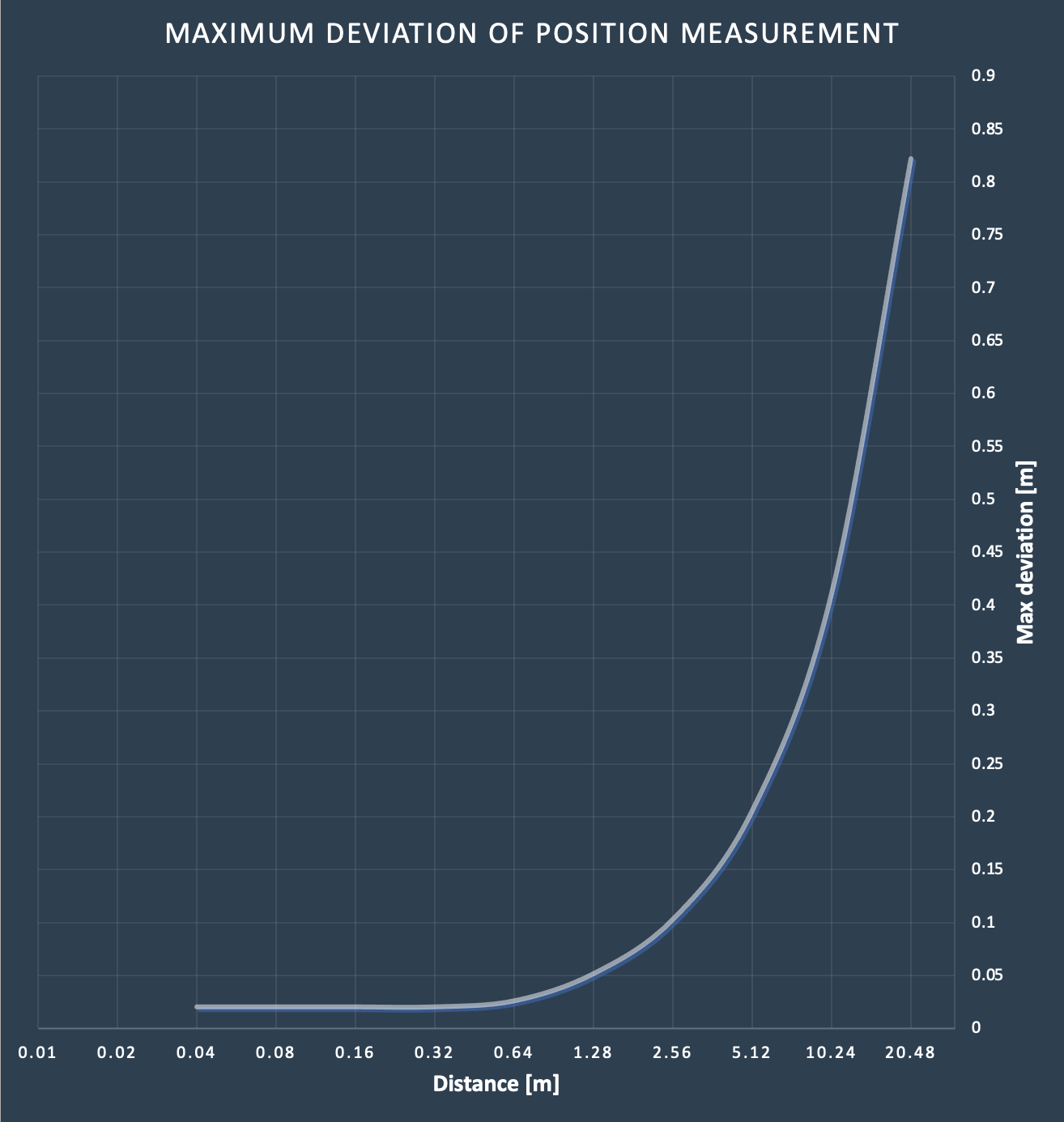
How accurate is the UAVLAS system?
The system relies on angle data received from the transmitter, and that the maximum error in measuring the system position changes in proportion to the distance from the transmitter to the receiver. For example, at a distance of 0.5 meters, the maximum error is estimated to be 2-3 centimeters for ULS-XCopter.
To get information about the uncertainty at different distances see deviation chart. For technical specifications, please refer to the corresponding sections of the documentation.
How will the system behave in case of an obstacle in the field of view?
The system is not affected by objects in the field of view of the system, provided that there is a line of sight between the photosensitive zone of the receiver and the transmitter. The system continues to work correctly even in the case of a temporary obstacle between the transmitter and the receiver for about 0.5-1 seconds. If the time is exceeded, the system informs the autopilot about the loss of the target. After the obstacle is removed, the system recovers its operation in 0.5-0.8 seconds.
How much does the onboard part of the system weigh?
The weight of the onboard part differs depending on the type of system and version. For example, the ULS-XCopter version of the receiver weighs less than 10 grams. This allows it to be mounted on drones of almost any payload capacity.
For technical specifications, please refer to the corresponding sections of the documentation.
Does the receiver have an IMU?
No. Because of its principle of operation, the receiving part of the system is invariant to orientation, there is no need to install an IMU system. However, it should be noted that in order to be able to transmit information to the autopilot in the coordinate system associated with the drone (North East Down Frame) the system requests from the drone information about the Yaw orientation of the aircraft.
Which operating system is suitable for installing the setup and updating software (ULS-Tools)?
ULS-Tool can run on Windows, Linux, and MacOs systems.
What autopilots can work with your system?
At the moment, our system works with the stock Ardupilot and PX4 firmware. However, thanks to the standard interfaces and protocols, it can be easily integrated into almost any system.
If you are using your own autopilot system, we can coordinate the communication protocol and help you to integrate our system.
Does the system need an altimeter to operate?
No. Our system independently calculates the distance to the beacon and uses this information to convert the angular position of the aircraft into the Cartesian coordinate system. Accordingly, the system transmits to the autopilot the fully calculated landing coordinates including the distance. By the way, it allows to landing on sites with different altitudes and where radar, laser and ultrasonic altimeter can not work or has a large error (e.g. towers, balconies).
Is it possible with your system to make the landing not vertically, but at an angle?
Yes. Our system allows you to land on the platform at an angle.
This is useful when it is necessary to climb onto a balcony or a ledge along a vertical wall, or, in other cases, when it is necessary to avoid the drone to enter a forbidden zone.
You can see an example in the video below.