# ArduPilot Integration Guide
> Connect any UAVLAS precision landing system to ArduPilot: PLND, serial and stream-rate parameters, LANDING_TARGET check, precision loiter and PID tuning.
---
Site [llms.txt](/llms.txt)
---
> **ULSDC-PBIG161026-AP** · version 1.0.0 · issued October 16, 2026
> The numbered PDF is the controlled copy: [download it from the portal](https://downloads.uavlas.com).
## Introduction
### Purpose
This guide describes how to connect a UAVLAS precision landing system to an ArduPilot (ArduCopter) autopilot, configure the autopilot, verify the link and tune precision loiter and landing.
### Intended Audience
Integrators and operators setting up precision landing on ArduPilot vehicles.
### Applicability
This guide applies to every UAVLAS precision landing system that connects to the autopilot over MAVLink: ULS-XCopter, ULS-ProCopter, ULS-Heli and ULS-XSpot. Product-specific installation, pinouts and wiring are in each product's Operation Manual and Interface Control Document.
## Integration
### Preparing for Integration
- Download the latest version of ULS-Tools. Connect all UAVLAS devices to a PC and update their firmware before proceeding.
- Update the autopilot to the latest ArduCopter version.
- Install the transmitter and receiver(s) and wire the receiver to a free autopilot UART (TELEM) port. Pinouts and wiring diagrams are in the Interface Control Document and Operation Manual of your product.
- Configure the transmitter in ULS-Tools.
- Configure the receiver in ULS-Tools (on dual-receiver systems, configure both receivers).
Generation 3 receivers (ULS-Heli-G3, ULS-XSpot-G3) have an RS422 interface. A UART-only autopilot needs the ULS-XX-UART-RS422 onboard adapter.
The system communicates with ArduPilot over MAVLink 2 and reports the target in MAV_FRAME_BODY_FRD.
**Example of receiver configuration:**
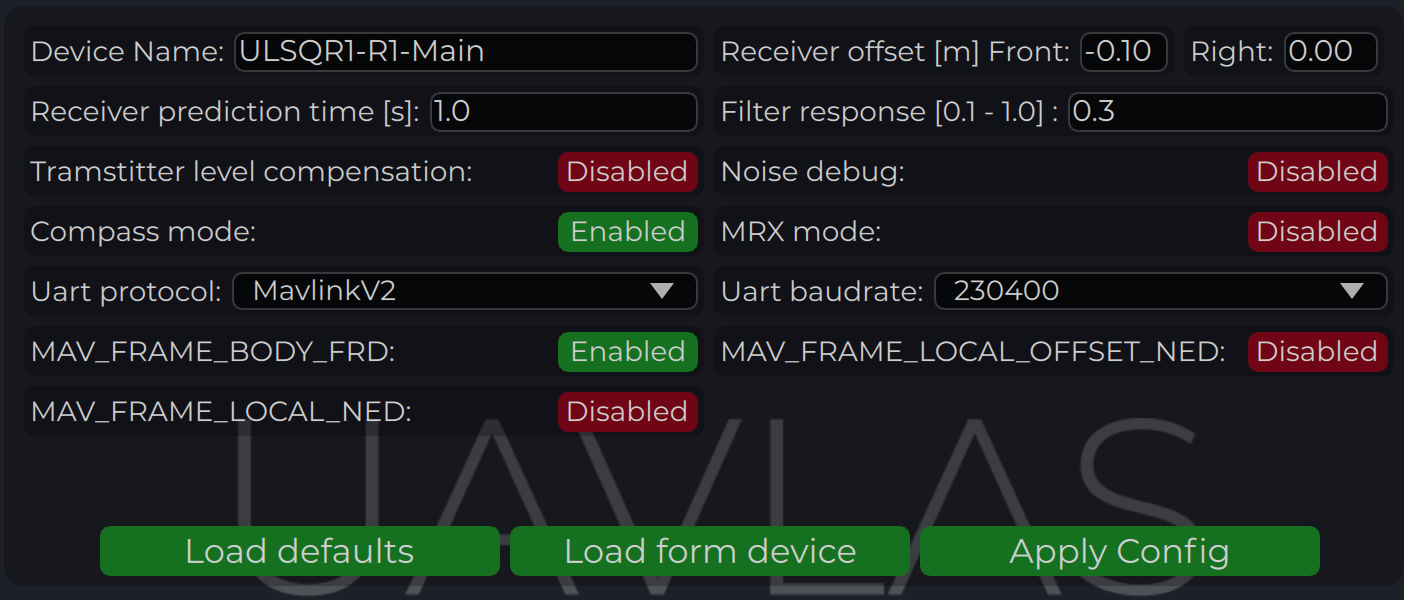
*Figure: Receiver Configuration for ArduPilot*
### Autopilot Configuration
#### Setup PLND Section
| Param | Value | Comment |
|-------|-------|---------|
| PLND_ENABLED | 1 | Enable the precision landing module |
| PLND_TYPE | 1 | Use type = 1 to enable UAVLAS sensor over the companion computer driver |
*Table: ArduPilot PLND Section Parameters*
All other PLND parameters should remain at defaults, or be set according to your vehicle requirements.
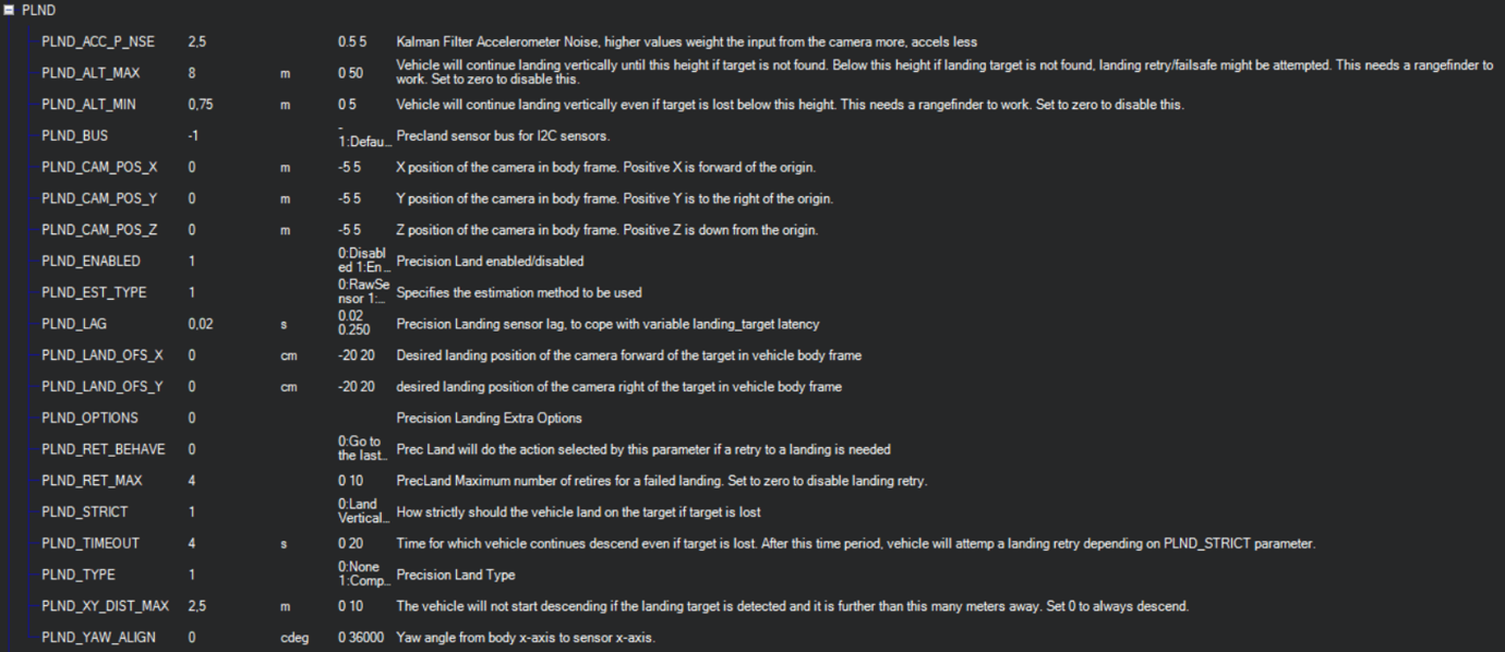
*Figure: PLND Configuration Example*
It is recommended to test several Kalman filter options during test flights (or switch it off) to achieve the best performance.
#### Set Up Serial Communication in SERIALx Section
The example uses SERIAL2; use the number of the port the receiver is wired to.
| Param | Value | Comment |
|-------|-------|---------|
| SERIAL2_BAUD | 230 | Baud rate — must match the receiver UART baud rate setting |
| SERIAL2_OPTIONS | 0 | Default |
| SERIAL2_PROTOCOL | 2 | MAVLink 2 protocol |
*Table: ArduPilot SERIALx Section Parameters*
Set up serial stream rates in the SRx section. The sensor requires the following data from the autopilot:
| Param | Value | Comment |
|-------|-------|---------|
| SR2_EXTRA1 (or MAV2_EXTRA1) | 20 | Attitude stream at 20 Hz — required for compass mode yaw orientation |
| SR2_POSITION (or MAV2_POSITION) | 20 | Optional — Vehicle LOCAL_POSITION_NED stream at 20 Hz for absolute target position calculation |
*Table: ArduPilot SRx Stream Rate Parameters*
#### Check Setup
When configuration and wiring are correct, GPS is available, and the receiver is in the field of view of the transmitter, you will see the **LANDING_TARGET** MAVLink message in the MAVLink Inspector (Mission Planner example shown):
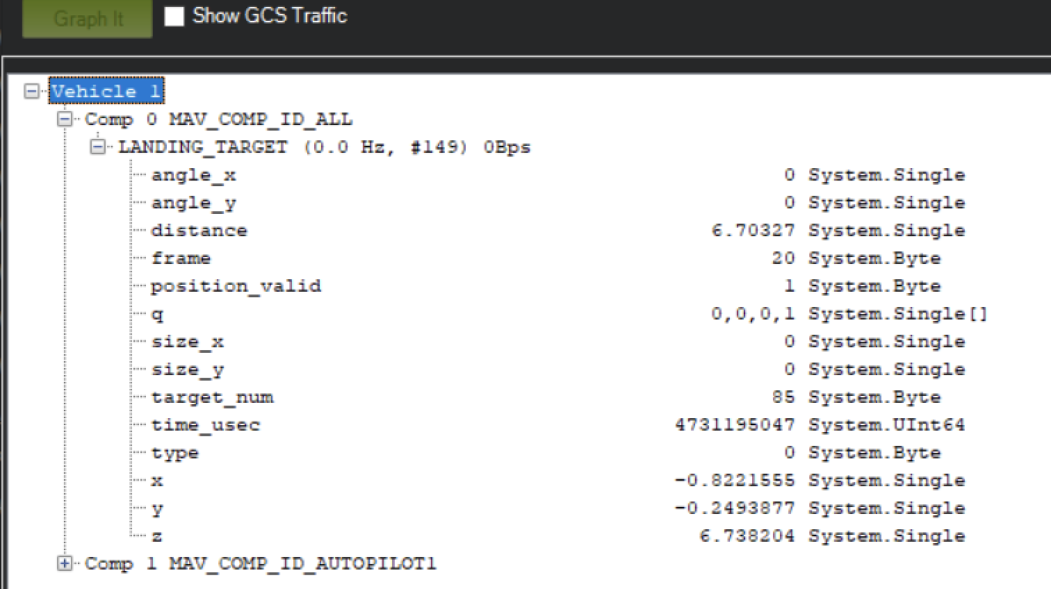
*Figure: LANDING_TARGET Message in MAVLink Inspector*
#### Setup Precision Loiter Mode
Attach any unused switch to the PrecLoiter option to enable precision loiter mode:
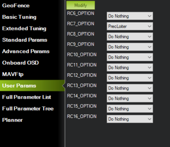
*Figure: PrecLoiter Switch Configuration*
Activate the switch and confirm messages "PrecLoiter: LOW" and "PrecLoiter: HIGH" appear. After a test flight above the target, check telemetry for PL offset data.
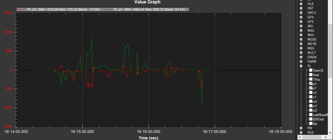
*Figure: Telemetry Data Showing PL Offsets*
#### PID Tuning
In case of oscillations or instability during landing, check the PID parameters in ArduPilot Extended Tuning.
It is recommended to tune Position XY, Velocity XY, and Loiter Speed for the best performance:
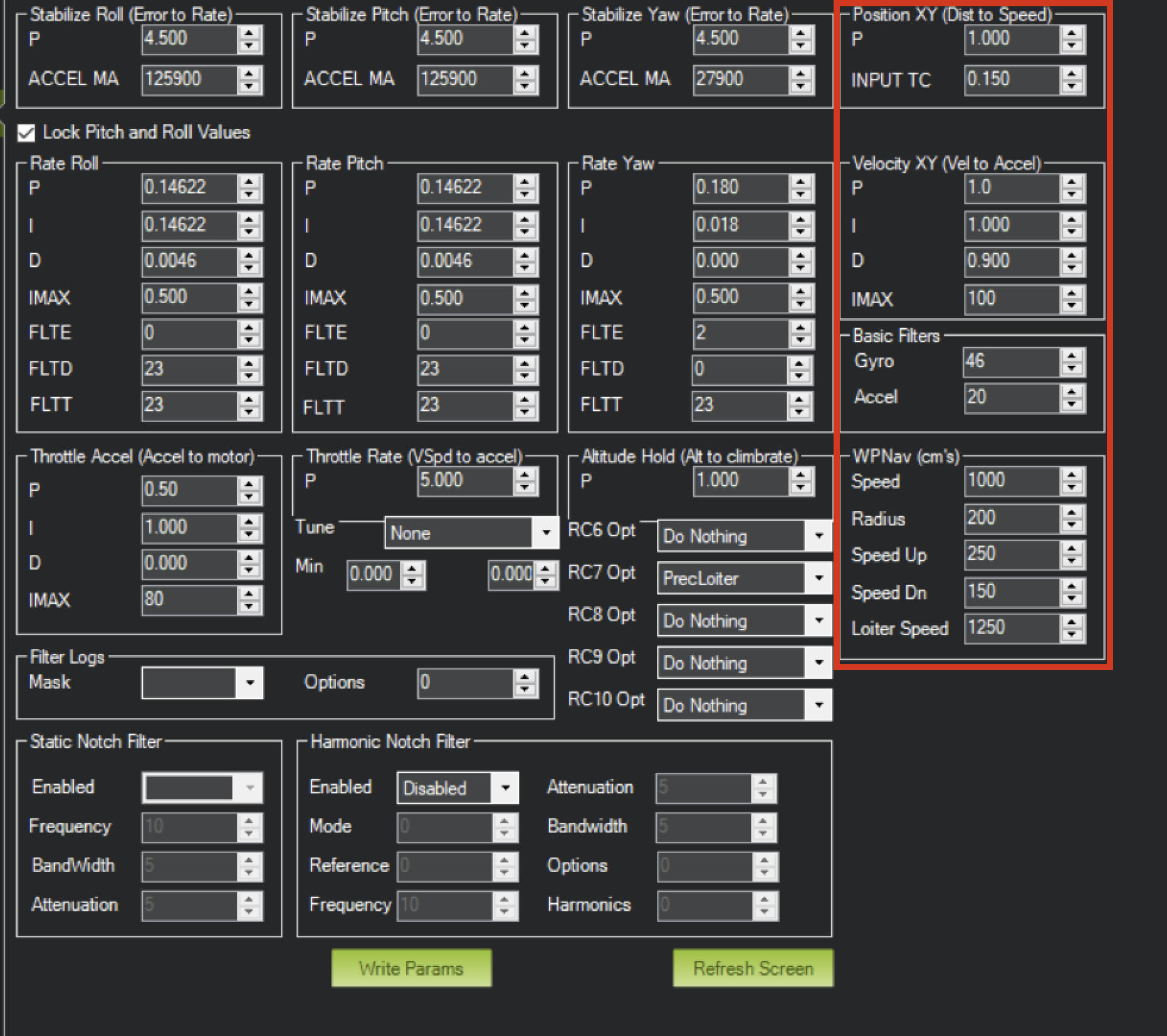
*Figure: ArduPilot Extended Tuning Parameters*
Settings of Velocity XY P = 0.8, I = 0.2, D = 0.6 have worked well for some customers as a starting point.
It is recommended to start PID testing and performance validation in Precision Loiter mode before enabling full precision landing.
For additional information, see the ArduPilot documentation at https://ardupilot.org/ardupilot/
---