ULS-XCopter-G2 Datasheet
ULSDC-PBDS310325 · version 0.1.0 · issued March 31, 2025
The numbered PDF is the controlled copy: download it from the portal.
Introduction
Purpose
The purpose of this datasheet is to provide comprehensive technical information about the ULS-XCopter-G2 System family. This includes specifications, performance characteristics, and detailed descriptions of system components, such as transmitters and receivers. By outlining the interfaces between these components, the datasheet aims to facilitate seamless integration and operation for system engineers, integrators, and developers working with the system.
Scope
This document is intended for use by system engineers, integrators, and developers working with ULS-XCopter-G2 systems. It provides detailed information on the system components, specifications, interfaces, and operational characteristics.
System Base Components
Transmitter (Ground Unit)
A transmitter is a device placed on the ground (platform, moving object). It emits a signal in the Infrared range and serves as a kind of beacon. Transmitter marks position for drone landing.
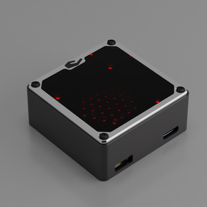
The primary function of the transmitter is to continuously send out a coded signal that can be detected and interpreted by the receiver unit onboard the XCopter. This signal contains critical information needed for the operation of the ULS-XCopter, such as positional data, commands, and system status.
Receiver (Onboard Unit)
A receiver is a device that is placed on board an aircraft.
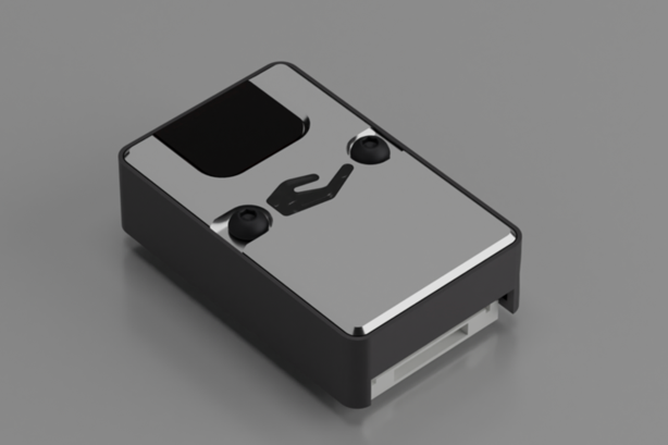
The receiver decodes this signal to derive flight information such as positional coordinates, real-time transmitter status updates, and landing guidance. It interprets the data to navigate accurately and ensure drone follows the intended flight path. It provides feedback to the autopilot systems, such as Ardupilot and PX4, to adjust the flight parameters as needed for optimal and safety landing or hovering above.
Part Numbering
| Part Number | Description |
|---|---|
| ULS-XCopter-G2 | System set with 1 receiver. Generation 2. |
| ULS-XCopter-G2-MRX | System set with 2 receivers. Generation 2. |
| ULSDV-XC-G2-TX | Transmitter unit. Generation 2. |
| ULSDV-XC-G2-RX | Receiver unit. Generation 2. |
| GHR-10V-S | 10 Pin Connector for receiver. Manufacturer, JST Commercial. |
| GHR-06V-S | 6 Pin Connector for transmitter. Manufacturer, JST Commercial. |
| GHR-04V-S | 4 Pin Connector for transmitter. Manufacturer, JST Commercial. |
Table: ULS-XCopter-G2 Part Numbers
System Specifications
Common Specification
| Parameter | XCopter-G2 |
|---|---|
| Distance range (m) | 0.1 - 20.0 |
| Working angle (deg) | 60 |
| Data update frequency (Hz) | 20 |
Table: Common System Specifications
Receiver (Onboard Unit)
| Parameter | XCopter-G2 |
|---|---|
| Field of view (deg) | 100 |
| Dimensions (mm) | 20 x 32 x 9 |
| Weight (g) | 10 |
| Power Consumption (W) | 0.3 |
| Voltage supply (V) | 5.0 |
| Interfaces | USB, CAN, UART |
Table: Receiver Specifications
Transmitter (Ground Unit)
| Parameter | XCopter-G2 |
|---|---|
| Field of emitting (deg) | 60 |
| Dimensions (mm) | 50 x 50 x 23 |
| Weight (g) | 45 |
| Power Consumption (W) | 2.4 |
| Voltage supply (V) | 7.5 - 27 |
| Interfaces | USB, CAN, UART |
Table: Transmitter Specifications
Pinout Information
Receiver Pinout
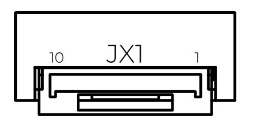
Figure: ULS-XCopter-G2 Receiver Connector
| Pin Number | XCopter-G2 |
|---|---|
| 1 | +5V Input |
| 2 | UART RX |
| 3 | UART TX |
| 4 | CAN H |
| 5 | CAN L |
| 6 | USB D- |
| 7 | USB D+ |
| 8 | UART2 RX |
| 9 | UART2 TX |
| 10 | GND |
Table: Receiver Pinout (JX1)
Transmitter Pinout
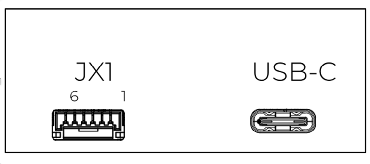
Figure: ULS-XCopter-G2 Transmitter Main Connector
| Pin Number | XCopter-G1&G2 |
|---|---|
| 1 | Vcc Input (+7.5V..+27V) |
| 2 | CAN2 H |
| 3 | CAN2 L |
| 4 | UART TX |
| 5 | UART RX |
| 6 | GND |
Table: Transmitter Main Connector Pinout (JX1)
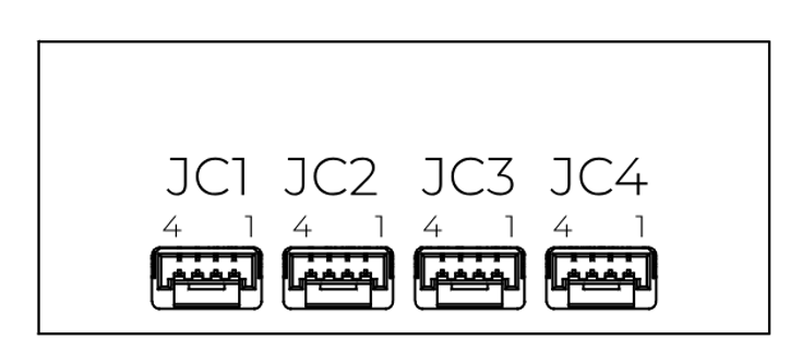
Figure: ULS-XCopter-G2 Transmitter Submodule Connectors
| Pin Number | XCopter-G1&G2 |
|---|---|
| 1 | +5V Output |
| 2 | CAN1 H |
| 3 | CAN1 L |
| 4 | GND |
Table: Transmitter Submodule Connectors Pinout (JC1-JC4)
Mechanical Dimensions
Receiver (G2) Dimensions
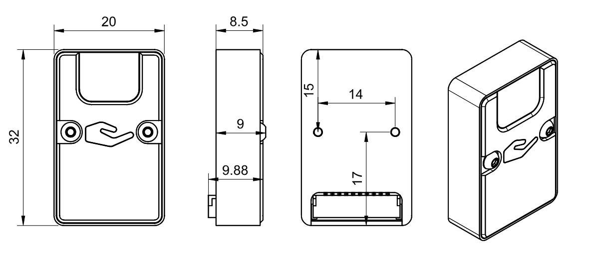
Figure: ULS-XCopter-G2 Receiver Dimensions (mm)
Transmitter (G2) Dimensions
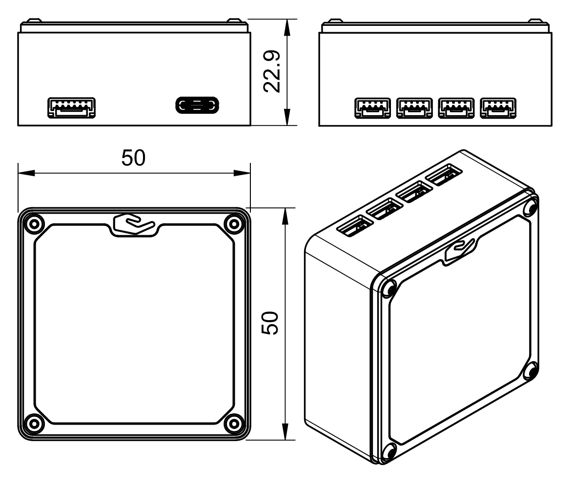
Figure: ULS-XCopter-G2 Transmitter Dimensions (mm)
Environmental Conditions
The system is designed for commercial-grade environmental operation, suitable for outdoor and industrial applications where robust performance under varying environmental conditions is required.
Operating Temperature
The system components are rated for extended temperature operation:
- Normal Operation: -20°C to +45°C when mounted on vehicle PCB
The wide operating temperature range enables deployment in diverse climates, from cold weather operations to hot desert environments.
Environmental Protection
- IP Protection Rating: IP54 (dust protected, splash water resistant)
- Note: While the system offers protection against dust ingress and water splashing, it is not waterproof. Additional protective measures may be required for operation in harsh weather conditions or marine environments.
Storage and Handling
- Storage Temperature: -40°C to +85°C
- Humidity: Up to 95% non-condensing
- Altitude: Operation up to 4000m above sea level
Environmental Considerations
Dust Protection: The IP54 rating provides protection against dust ingress that could interfere with system operation. Regular cleaning is recommended in particularly dusty environments.
Moisture Resistance: Protected against water splashing from any direction. However, avoid direct water jets, submersion, or prolonged exposure to heavy rain without additional protective enclosures.
Thermal Management: Ensure adequate ventilation around system components during operation. Avoid mounting in locations exposed to direct sunlight or near heat sources that could cause components to exceed maximum operating temperature.
Condensation: When moving equipment between environments with significant temperature differences, allow sufficient time for thermal equalization to prevent internal condensation.
| Parameter | Minimum | Maximum | Unit | Notes |
|---|---|---|---|---|
| Operating Temperature | -25 | +45 | °C | Normal operation |
| Storage Temperature | -40 | 85 | °C | Non-operating |
| Humidity | 5 | 95 | % | Non-condensing |
| IP Protection Rating | IP54 | Dust and splash resistant | ||
| Altitude | 0 | 4000 | m | Above sea level |
Table: Environmental Specifications - Commercial Grade
Performance Characteristics
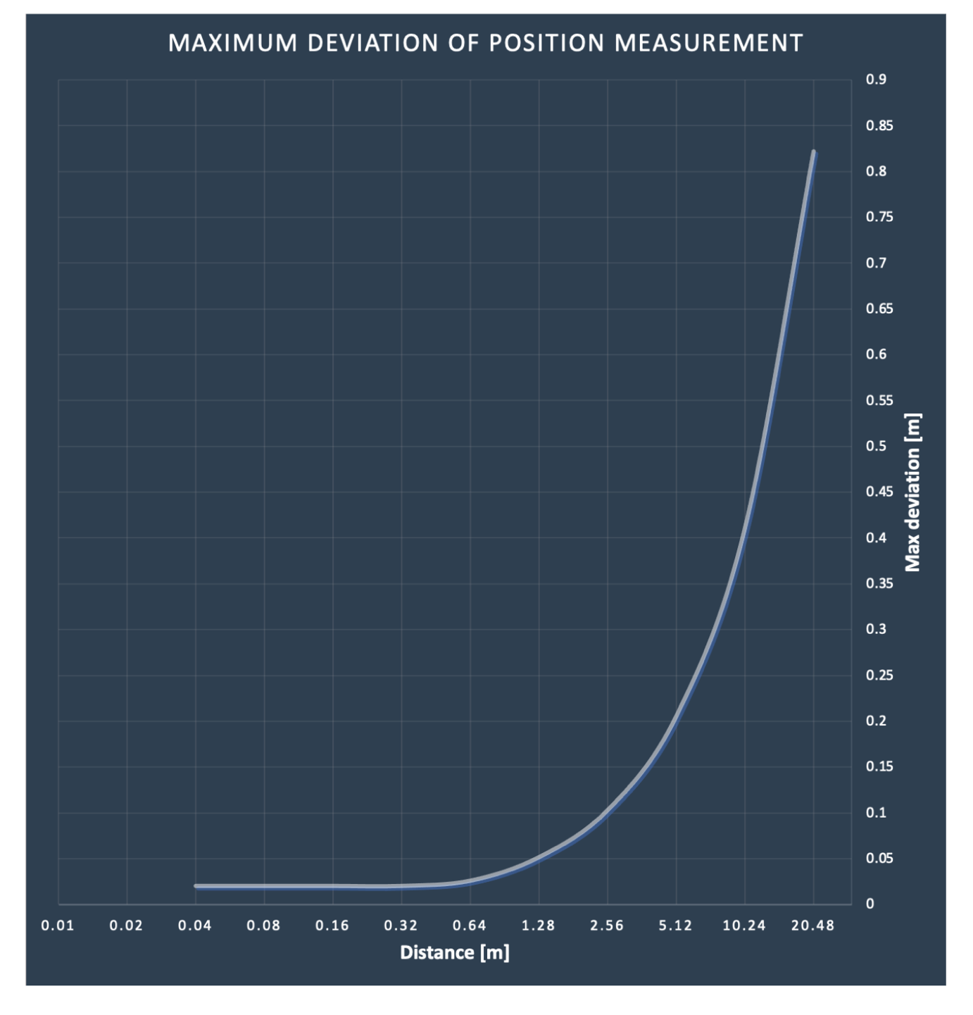
Figure: ULS-XCopter-G2 Performance Characteristics
Packaging Information
Basic System (PN: ULS-XCopter-G2)
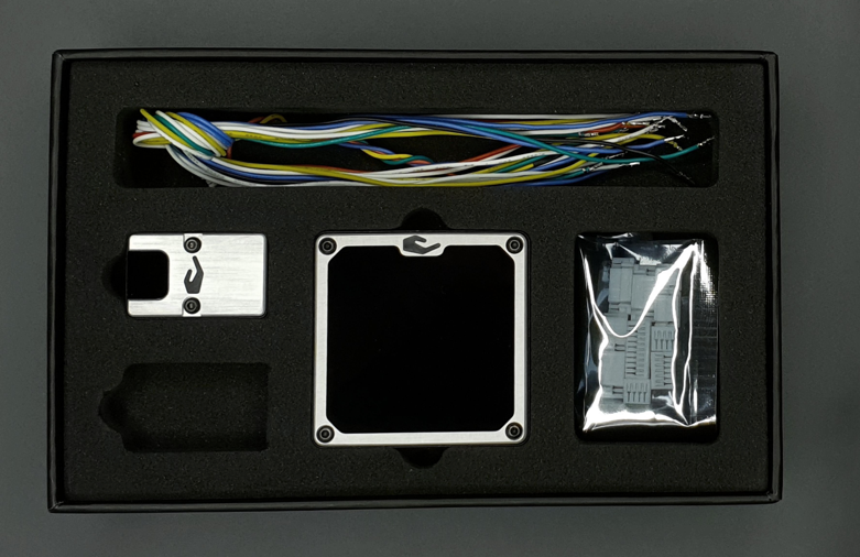
Figure: ULS-XCopter-G2 System Packaging
Advanced System (PN: ULS-XCopter-G2-MRX)
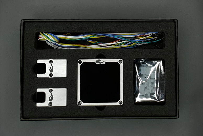
Figure: ULS-XCopter-G2-MRX
Packed systems
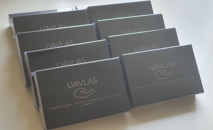
Figure: ULS-XCopter-G2 in boxes
Feedback
Was this page helpful?
Glad to hear it! Please tell us how we can improve this page !
Sorry to hear that. Please tell us how we can improve it !