ULS-XSpot Interface Control Document
ULSDC-PBICD231125 · version 1.0.2 · issued November 23, 2025
The numbered PDF is the controlled copy: download it from the portal.
Introduction
Purpose
This document outlines the interfaces between the ULS-XSpot system components, including the tether-compatible transmitter, receiver, and autopilot systems (Ardupilot, PX4, and similar). The ULS-XSpot is specifically designed for tethered drone operations with a 50-meter working range.
Scope
This document is intended for use by system engineers, integrators, and developers working with ULS-XSpot systems in tethered drone applications. It provides detailed information on the interfaces between the system components, ensuring seamless integration and operation with tether management systems.
Key Features for Tethered Operations
- Tether-Compatible Design: Center hole in transmitter for cable passage
- Working Range: 50-meter working distance
- Standard IR Optical: No DACS technology required
- Continuous Operation: Designed for 24/7 operation with tethered power
System Components
Transmitter (Ground Unit - Tethered Design)
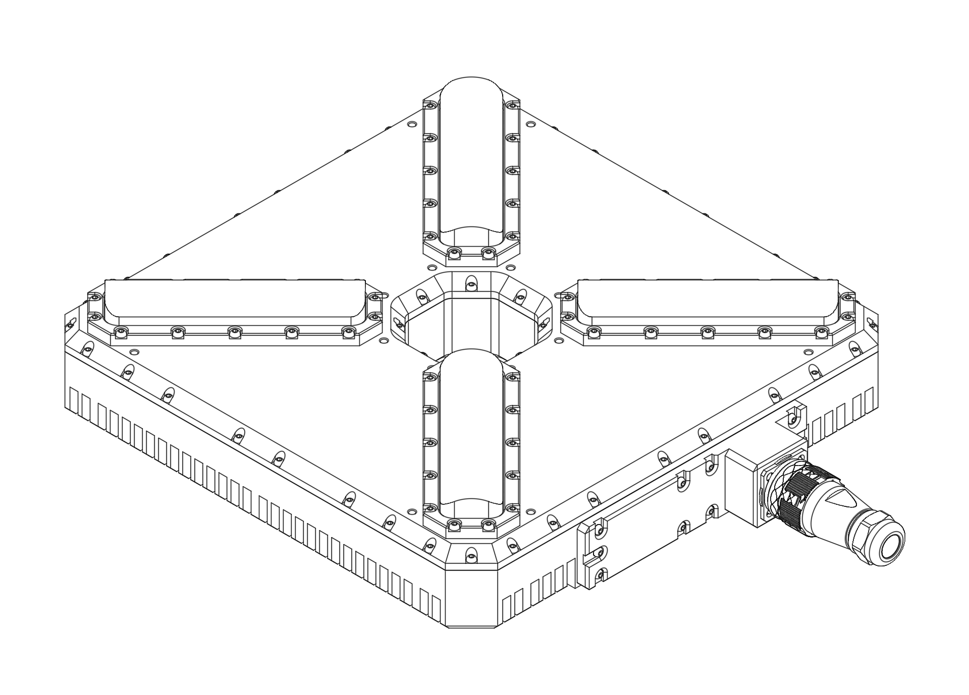
Figure: ULS-XSpot Transmitter with Center Tether Hole The ULS-XSpot transmitter is specifically designed for tethered drone systems. It features a center hole for tether passage, allowing the drone’s power and data cable to pass through while maintaining optical positioning capabilities. The transmitter is placed on the ground (platform, moving object) and emits a signal in the Infrared range, serving as a positioning beacon for tethered drone landing and station-keeping.
The primary function of the transmitter is to continuously send out a coded signal that can be detected and interpreted by the receiver unit onboard the tethered copter. This signal contains critical information needed for the operation of the system, such as positional data and status. The tethered design allows for extended flight duration while maintaining precision positioning.
Key Features:
- Center hole for tether cable passage (integrated tether management)
- Working range: 50 meters working distance
- Optimized for tethered drone operations
- Continuous power available via tether connection
Receiver (Onboard Unit)
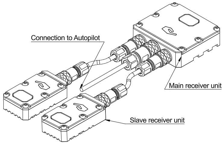
Figure: ULS-XSpot Receiver The receiver is a device that is placed on board the tethered aircraft. The receiver decodes the IR signal to derive flight information such as positional coordinates, real-time transmitter status updates, and positioning guidance. It interprets the data to navigate accurately and ensure the drone maintains its position relative to the ground station. It provides feedback to autopilot systems, such as Ardupilot and PX4, to adjust the flight parameters as needed for optimal station-keeping, landing, or hovering operations while connected to the tether.
Key Features:
- Compatible with tethered drone configurations
- Real-time position feedback for station-keeping
- Seamless integration with tether management systems
Interface Overview
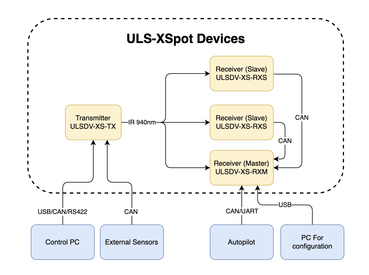
Figure: ULS-XSpot System Interfaces Overview
Note: The ULS-XSpot uses the same interface architecture as ULS-Heli-G2, with the addition of tether-compatible mechanical design.
Transmitter to Control PC Interface (External Sensors)
The transmitter can be connected to a control PC or external equipment for configuration, status monitoring, and data exchange.
Data Types
- Status information
- Control signals
- Transmitter configuration
- External IMU/COMPASS data
Connection Types
- CAN Bus - For network communication
- USB - For configuration and firmware updates
- RS422 - For serial communication with external sensors
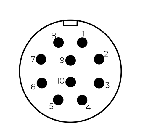
Transmitter Pinout
| Pin | Function |
|---|---|
| 1 | Vin +18V – +28V |
| 2 | RS422A |
| 3 | RS422B |
| 4 | RS422Y |
| 5 | RS422Z |
| 6 | CAN-L |
| 7 | CAN-H |
| 8 | USB-D- |
| 9 | USB-D+ |
| 10 | GND |
Table: Transmitter 10 Pin Connector Pinout
Tethered System Note: When routing tether cable through the center hole, ensure the cable does not interfere with connector access or IR emission pattern.
Transmitter to Receiver Interface
The transmitter and receiver use an optical interface to exchange data. Transmission uses IR emission at 940 nanometers. Data transmission is only in the direction from the transmitter to the receiver.
Optical Range and Performance
| Parameter | ULS-XSpot | ULS-Heli-G2 | Notes |
|---|---|---|---|
| Maximum Range | 50m | 50m | Same range |
| Working Angle | 60° | 60° | Emission cone |
| Technology | Standard IR | IR + DACS | Simplified for tethered use |
| Update Rate | 20Hz | 20Hz | Same performance |
Table: Optical Interface Comparison
Data Types
- Position encoded
- Status encoded data (Transmitter orientation and instructions)
Connection Type
- Optical IR 940nm - Infrared optical link
Tethered Operation: The 50-meter range covers typical tethered drone operating heights. Tether provides stable reference, reducing positioning complexity compared to free-flight applications.
Receiver to Autopilot and Receiver to PC Interfaces
Data Types
- MAVLink messages
- ULS-Blitz frames
- ASCII protocol
Connection Types
- UART - Serial communication with autopilot
- CAN - Network communication
- USB - Direct PC connection
Receiver Pinout
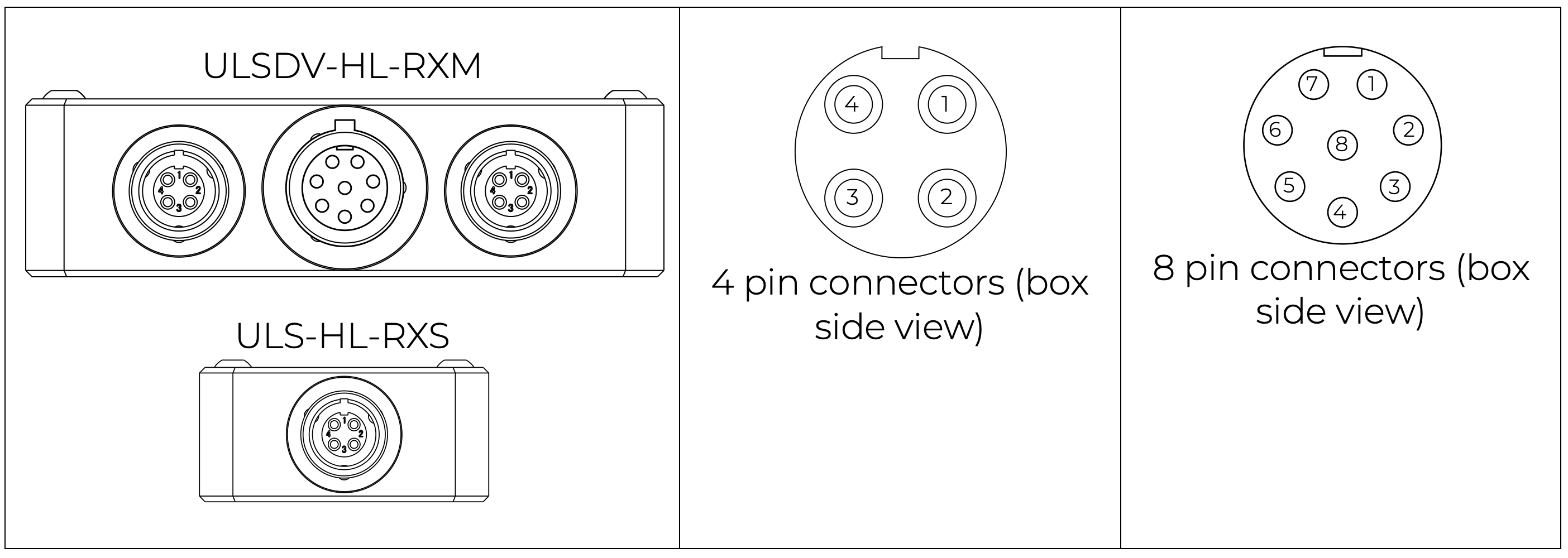
| Pin | Function |
|---|---|
| 1 | Vin (+5V) |
| 2 | CANH |
| 3 | CANL |
| 4 | GND |
Table: 4 Pin Connector Pinout
| Pin | Function |
|---|---|
| 1 | Vin (+5V) |
| 2 | CANH |
| 3 | CANL |
| 4 | UART_TX (OUT) |
| 5 | UART_RX(IN) |
| 6 | USB_D- |
| 7 | USB_D+ |
| 8 | GND |
Table: 8 Pin Connector Pinout
Powering Interfaces
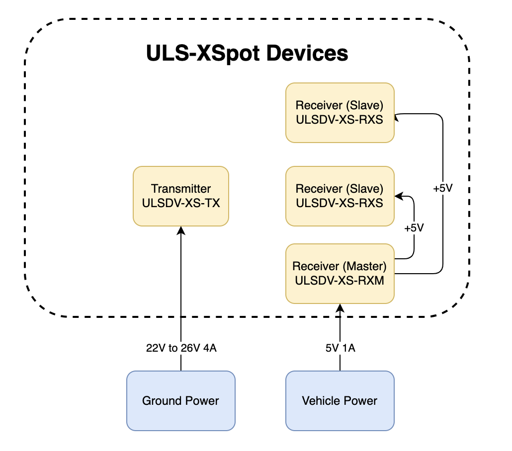
Figure: Power Distribution and Connections
Transmitter Electrical Characteristics
| Parameter | Value | Unit | Notes |
|---|---|---|---|
| Supply Voltage | 22.0 - 26.0 | V | Nominal 24V |
| Supply Current | 4 | A | Peak |
| Power Consumption | 18.1 | W | Typical |
Table: Transmitter Electrical Specifications Tethered System Power: Transmitter can be continuously powered from ground station power supply. Consider tether voltage drop when sizing power system for long tether runs.
Receiver Electrical Characteristics
| Parameter | Value | Unit | Notes |
|---|---|---|---|
| Supply Voltage | 5.0 | V | From flight controller or tether |
| Supply Current | 1 | A | Peak |
| Power Consumption | 3 | W | Typical |
Table: Receiver Electrical Specifications Tethered Power Option: Receiver can be powered from flight controller or directly from tether power distribution system.
Functional Diagram
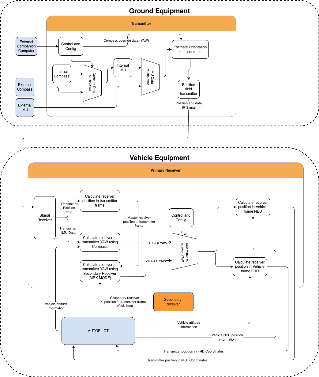
Figure: Functional description of the system
Functional Interfaces
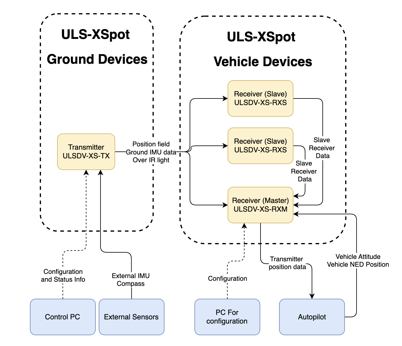
Figure: Data Flow and Functional Interfaces
Data Exchange
The ULS-XSpot system implements several data exchange mechanisms optimized for tethered operations:
Control PC Functions:
- Configure and view status of transmitter
- Set configuration of receivers
- Send control signals (On/off, compass override information)
- Monitor tethered operation parameters
External Equipment:
- External IMU/Compass equipment can be used to override internal IMU/compass information
- Tether management system integration for position reference
Receiver Functions:
- Accept data from transmitter over IR signal (position field information and ground unit IMU data)
- Accept NED and Attitude information from autopilot to convert coordinate system
- Multiple receivers can communicate to calculate vehicle orientation (YAW)
- Send position offset data to autopilot
- Support for tethered flight modes and station-keeping
Tethered System Integration
Ground Station Interface:
- Power distribution to transmitter via ground power supply
- Data connection for configuration and monitoring
- Tether management system coordination
Aircraft Interface:
- Position data from ULS-XSpot receiver to autopilot
- Tether tension and status monitoring (external system)
- Coordinated flight control for tethered operations
Mechanical Interfaces
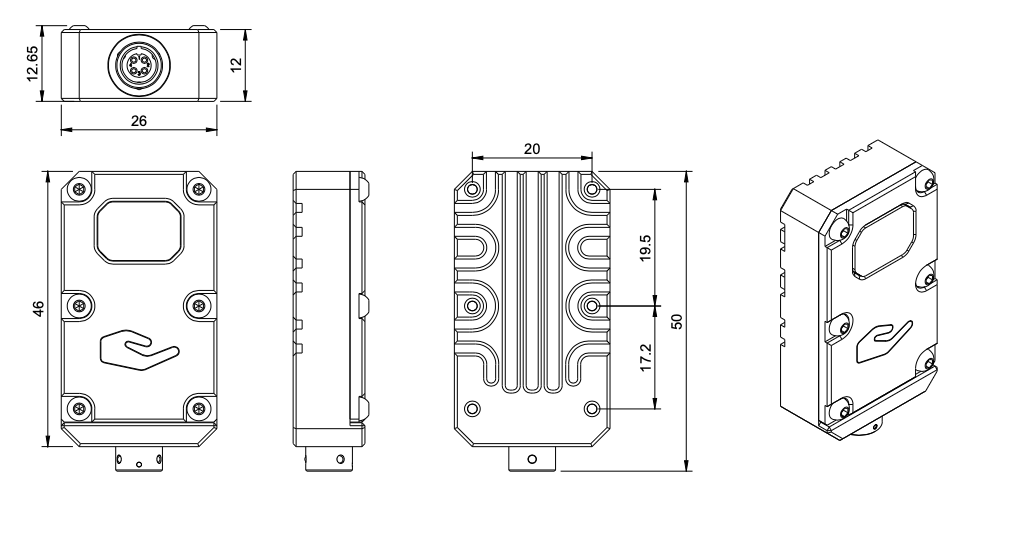
Figure: Slave Receiver Mechanical Dimensions
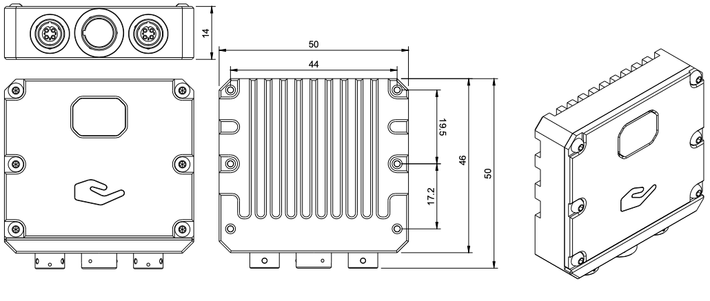
Figure: Master Receiver Mechanical Dimensions
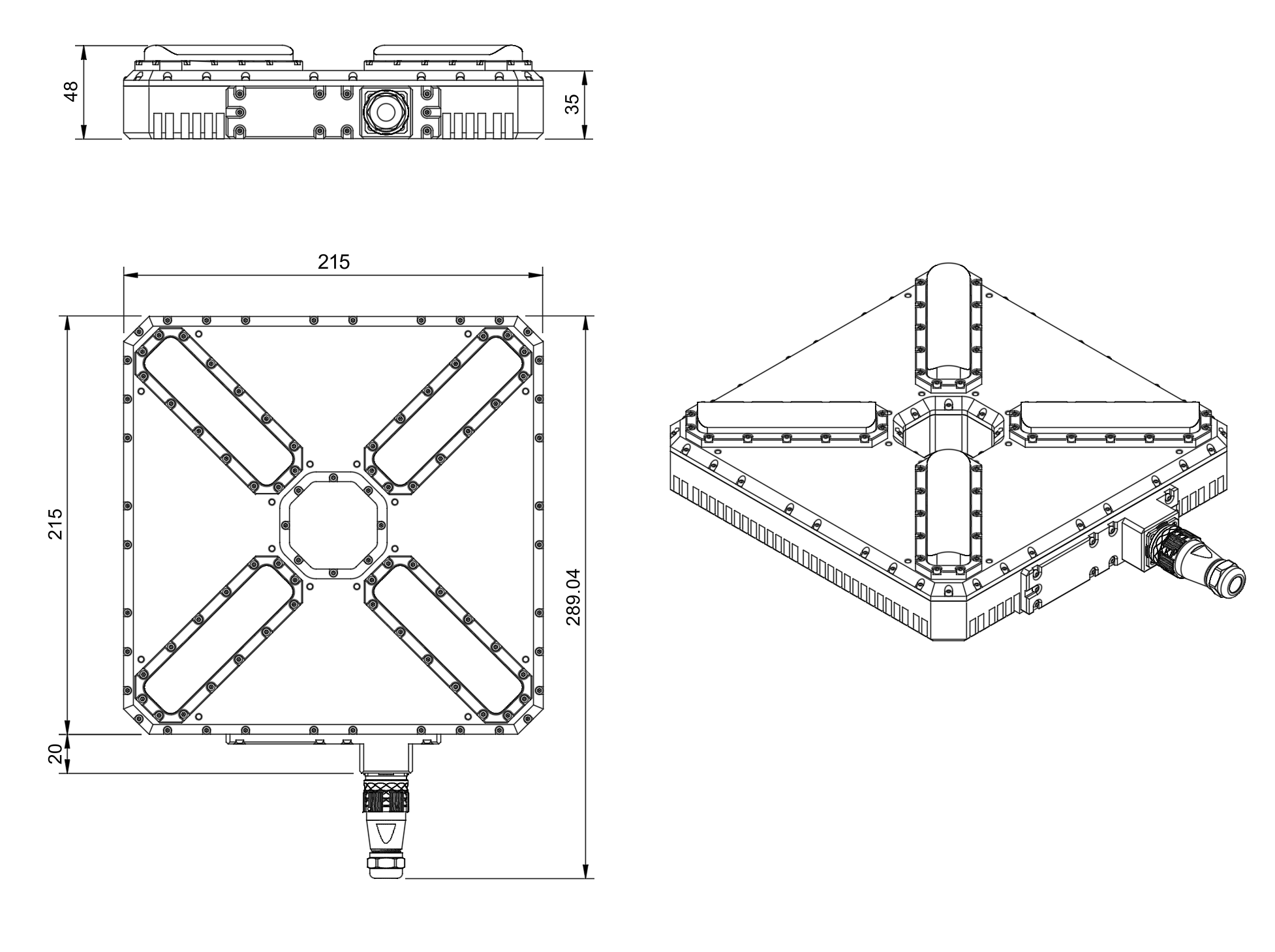
Figure: Transmitter Mechanical Dimensions with Center Tether Hole
Note: The transmitter features a center hole designed for tether cable passage, enabling integration with tethered drone power and data systems.
Transmitter Mounting with Tether
The transmitter features a center hole for tether passage. Key mounting considerations:
- Use 16 mounting holes to secure transmitter to platform
- Route tether cable through center hole before mounting
- Ensure tether has adequate strain relief above and below transmitter
- Maintain 10cm minimum clearance around transmitter for IR emission
- Verify tether routing does not obstruct 60° emission cone
Receiver Mounting
Both master and slave receivers have mounting provisions for secure installation on tethered aircraft. 3D models of the receivers can be provided upon request.
Tethered Aircraft Considerations:
- Position receivers to avoid tether shadow/obstruction
- Consider tether dynamics in receiver placement
- Maintain clear line-of-sight to ground transmitter
Communication Protocols
Overview
The protocol used by devices for configuration is proprietary and is described in other documents. However, the protocol implements the possibility of transmitting messages (Blitz messages) that can be used by the user to control the device and obtain information. These messages are universal, and the format describes the data that is transmitted by various devices in our system connected to a single network.
Use CMD=6 to send Blitz messages.
In this document, the CAN protocol is specified. RS485 is used to implement custom protocols that can be defined in the future.
CAN Bus Protocol Frame Format
flowchart LR
  A[Sender Device] --> B[GLOBAL]
  B --> C[CMD = 6]
  C --> D[ID]
  D --> E[dsn_lid]
  E --> F[msg_id]
  F --> G[Blitz Payload data <= 8 bytes]
  G --> H[Receiver Device]
The CAN protocol uses the following frame structure:
| Field | Description |
|---|---|
| GLOBAL | Flag used to send packets over several local networks |
| CMD | Command field (Use CMD=6 to send Blitz messages) |
| ID | Packet sender ID (local id src_lid for local packets and device id for global packets src_did) |
| dsn_lid | Destination local ID address |
| msg_id | Message ID used to identify Blitz packet types |
Table: CAN Protocol Frame Fields
Status Bit Definitions
Most messages include a status byte with the following bit definitions:
| Bit | Flag | Description |
|---|---|---|
| 0 | ULS_STATUS_RX_CARRIER_OK | IR signal detected |
| 1 | ULS_STATUS_RX_SQ_OK | Signal quality OK |
| 2 | ULS_STATUS_RX_POS_OK | Position estimated |
| 3 | ULS_STATUS_RX_VEL_OK | Velocity estimated |
| 4 | ULS_STATUS_RX_GU_IMU_OK | Ground Unit IMU OK |
| 5 | ULS_STATUS_RX_MRX_OK | MRX message received (secondary receiver) |
| 6 | ULS_STATUS_RX_MRXDATA_OK | MRX Yaw and Distance calculated OK |
Table: Status Bit Definitions
Common Data Structure
Blitz Common Data Structure
Structure: __blitz_common_data_struct
| Field | Type | Description |
|---|---|---|
src_lid | uint8_t | Source logical ID |
msg_id | uint16_t | Message ID (see message types below) |
data | union | Message-specific data (8 bytes max) |
Table: Blitz Common Data Structure The union contains all possible message structures:
xcg1_rx_raw_measurmetrx_raw_measurmetrx_pos_in_tx_framerx_mrxrx_dacs
Usage: Universal container for all ULS Blitz message types.
Implementation Notes
- Packed Structures: All structures use
__attribute__((packed))to ensure no padding bytes are added by the compiler. - Endianness: The protocol assumes little-endian byte order for multi-byte fields.
- Angular Precision: Angular measurements use 16-bit signed integers with specific scaling factors for different ranges.
- Distance Units: Distance measurements may use different units (cm, 10cm increments) depending on the message type.
Message Types
XCG1 Raw Measurement (0x0010)
Message ID: ULS_BLITZ_MSG_ID_XCG1_RX_RAW_MEASURMENT (0x0010)
Structure: __uls_blitz_xcg1_rx_raw_measurmet
| Field | Type | Description |
|---|---|---|
status | uint8_t | Status bits (see Status Bit Definitions above) |
d | uint8_t | Distance in 10 cm increments |
aX | int16_t | Angular information X-axis, proportional [-30000 = -30°, +30000 = +30°] |
aY | int16_t | Angular information Y-axis, proportional [-30000 = -30°, +30000 = +30°] |
oF | int8_t | Sensor offset Forward in cm |
oR | int8_t | Sensor offset Right in cm |
Table: XCG1 Raw Measurement Message Format Purpose: Legacy raw measurement data for XCG1 systems with limited angular range.
Raw Measurement (0x0011)
Message ID: ULS_BLITZ_MSG_ID_RX_RAW_MEASURMENT (0x0011)
Structure: __uls_blitz_msg_rx_raw_measurmet
| Field | Type | Description |
|---|---|---|
status | uint8_t | Status bits (see Status Bit Definitions above) |
counter | uint8_t | Message counter for tracking |
aX | int16_t | Angular information X-axis [-180° to +180°] |
aY | int16_t | Angular information Y-axis [-180° to +180°] |
distance | uint16_t | Distance measurement |
Table: Raw Measurement Message Format Angular Conversion Formula:
degrees = (value_int16 * 180.0f) / 32767.0f
Purpose: Standard raw measurement data with full angular range.
Position in TX Frame (0x0012)
Message ID: ULS_BLITZ_MSG_ID_RX_POS_IN_TX_FRAME (0x0012)
Structure: __uls_blitz_msg_rx_pos_in_tx_frame
| Field | Type | Description |
|---|---|---|
status | uint8_t | Status bits (see Status Bit Definitions above) |
counter | uint8_t | Message counter for tracking |
posX | int16_t | Position X-coordinate in transmitter frame (cm) |
posY | int16_t | Position Y-coordinate in transmitter frame (cm) |
posZ | int16_t | Position Z-coordinate in transmitter frame (cm) |
Table: Position in TX Frame Message Format Purpose: 3D position data relative to the transmitter coordinate system.
MRX Information (0x0013)
Message ID: ULS_BLITZ_MSG_ID_RX_MRX (0x0013)
Structure: __uls_blitz_msg_rx_mrx
| Field | Type | Description |
|---|---|---|
status | uint8_t | Status bits (see Status Bit Definitions above) |
counter | uint8_t | Message counter for tracking |
yaw | int16_t | Yaw angle [-180° to +180°] |
distance | uint16_t | Distance measurement in cm |
Table: MRX Information Message Format Purpose: Multi-receiver (MRX) information for secondary receiver data.
DACS Information (0x0014)
Message ID: ULS_BLITZ_MSG_ID_RX_DACS (0x0014)
Structure: __uls_blitz_msg_rx_dacs
| Field | Type | Description |
|---|---|---|
status | uint8_t | Status bits (see Status Bit Definitions above) |
counter | uint8_t | Message counter for tracking |
yaw | int16_t | Yaw angle [-180° to +180°] |
distance | uint16_t | Distance measurement |
yawContinuous | int16_t | Continuous yaw angle ±32768° |
Table: DACS Information Message Format Purpose: DACS (Distance and Azimuth Correction System) data with continuous yaw tracking. Available on VTOL systems only.
Ground IMU Measurement (0x0020)
Message ID: ULS_BLITZ_MSG_ID_GIMU_MEASUREMENT (0x0020)
Structure: __uls_blitz_msg_gimu_data
| Field | Type | Description |
|---|---|---|
status | uint8_t | Status bits (see Status Bit Definitions above) |
counter | uint8_t | Message counter for tracking |
roll | int16_t | Roll angle [-180° to +180°] |
pitch | int16_t | Pitch angle [-180° to +180°] |
yaw | int16_t | Yaw angle [-180° to +180°] |
Table: Ground IMU Measurement Message Format Angular Conversion Formula:
degrees = (value_int16 * 180.0f) / 32767.0f
Purpose: Ground unit IMU (Inertial Measurement Unit) orientation data.
IMU Override (0x0030)
Message ID: ULS_BLITZ_MSG_ID_XX_TXC_IMU_OVERRIDE (0x0030)
Structure: __uls_blitz_msg_xx_txc_imu_override
| Field | Type | Description |
|---|---|---|
control | uint8_t | Control bits (see Control Bits below) |
counter | uint8_t | Message counter for tracking |
roll | int16_t | Override roll angle [-180° to +180°] |
pitch | int16_t | Override pitch angle [-180° to +180°] |
yaw | int16_t | Override yaw angle [-180° to +180°] |
Table: IMU Override Message Format Control Bits:
| Bit | Description |
|---|---|
| 0 | SET Roll - Enable roll angle override |
| 1 | SET Pitch - Enable pitch angle override |
| 2 | SET Yaw - Enable yaw angle override |
| 3-7 | Reserved |
Table: IMU Override Control Bits Angular Conversion Formula:
degrees = (value_int16 * 180.0f) / 32767.0f
Purpose: Override IMU data on ground unit for external orientation control.
Magnetometer Override (0x0031)
Message ID: ULS_BLITZ_MSG_ID_XX_TXC_MAG_OVERRIDE (0x0031)
Structure: __uls_blitz_msg_xx_txc_mag_override
| Field | Type | Description |
|---|---|---|
control | uint8_t | Control bits (see Control Bits below) |
counter | uint8_t | Message counter for tracking |
mx | int16_t | Magnetic field X-component |
my | int16_t | Magnetic field Y-component |
mz | int16_t | Magnetic field Z-component |
Table: Magnetometer Override Message Format Control Bits:
| Bit | Description |
|---|---|
| 0 | SET override - Enable magnetometer override |
| 1-7 | Reserved |
Table: Magnetometer Override Control Bits Magnetic Field Conversion Formula:
mag_value = (value_int16 * 1.0f) / 32767.0f
Purpose: Override magnetometer data on ground unit for external compass control.
Tethered System Note: CAN bus protocol can be extended over tether for ground station integration if required.
Environmental Conditions - Industrial Grade
Equipment is designed to operate reliably in demanding environmental conditions typical of aerospace, industrial automation, and outdoor applications.
Operating Temperature Range
- Standard operating range: -20°C to +55°C
- Covers most industrial and outdoor applications
- Reliable performance across temperature extremes
- No performance degradation within specified range
Humidity Tolerance
- Relative humidity: Up to 70% (non-condensing)
- Protected against moisture in typical operating conditions
- Suitable for outdoor and semi-protected installations
- Condensation prevention through sealed design
Ingress Protection
- IP67 rated (Dust tight and water immersion resistant)
- 6 - Complete protection against dust ingress
- 7 - Protected against temporary immersion in water (up to 1 meter depth for 30 minutes)
- Suitable for harsh industrial environments
- Protected against rain, splashing, and temporary submersion
- Dust-tight sealing for contaminated environments
Storage Conditions
- Storage temperature: -40°C to +70°C
- Relative humidity: Up to 95% (non-condensing)
- Long-term storage in industrial facilities
Operational Environment Standards
- Designed to meet industrial equipment requirements
- Suitable for UAV/drone applications
- Outdoor installation capable
- Protected against:
- Dust and particulate matter
- Water spray and rain
- Temporary water immersion
- Temperature fluctuations
- High humidity
Part Numbering
| Part Number | Description |
|---|---|
| ULS-XSPOT | System set with 3 receivers for tethered drone systems. |
| ULSDV-XS-TX | Transmitter unit with center tether hole. |
| ULSDV-XS-RXM | Master receiver unit. |
| ULSDV-XS-RXS | Slave receiver unit. |
| SA610/P4IB | 4 Pin Connector for receiver. Manufacturer Weipu. |
| SA810/P8IIB | 8 Pin Connector for receiver. Manufacturer Weipu. |
| SA1610/P10IIB-1 | 10 Pin Connector for transmitter. Manufacturer Weipu. |
Table: Part Numbering
Tethered System Specific Interfaces
Tether Cable Specifications
Recommended tether cable specifications for integration with ULS-XSpot:
| Parameter | Specification | Notes |
|---|---|---|
| Center Hole Diameter | 20-50mm | Accommodates various tether sizes |
| Cable Clearance | Minimum 10mm | Around IR emission area |
| Strain Relief | Required | Both ends of transmitter |
| Cable Weight | Considered | Does not affect IR transmission |
Table: Tether Integration Specifications
Ground Station Integration
The ULS-XSpot transmitter should be integrated with the ground station tether management system:
- Power Connection: 24V DC supply from ground station
- Data Connection: USB or CAN for configuration/monitoring
- Mechanical Integration: Mounted at tether launch/recovery point
- Cable Management: Integrated with tether handling system
Safety Considerations
- Tether provides physical backup to optical positioning
- Loss of optical signal does not mean loss of tether connection
- Emergency procedures should account for tether recovery
- Regular inspection of tether routing through transmitter
Feedback
Was this page helpful?
Glad to hear it! Please tell us how we can improve this page !
Sorry to hear that. Please tell us how we can improve it !