ULS-ProCopter Datasheet
ULSDC-PBDS070425 · version 1.0.0 · issued June 14, 2025
The numbered PDF is the controlled copy: download it from the portal.
Introduction
Purpose
The purpose of this datasheet is to provide comprehensive technical information about the ULS-ProCopter System family. This includes specifications, performance characteristics, and detailed descriptions of system components, such as transmitters and receivers. By outlining the interfaces between these components, the datasheet aims to facilitate seamless integration and operation for system engineers, integrators, and developers working with ULS-ProCopter systems.
Scope
This document is intended for use by system engineers, integrators, and developers working with ULS-ProCopter systems. It provides detailed information on the system.
System Base Components
Transmitter (Ground Unit)
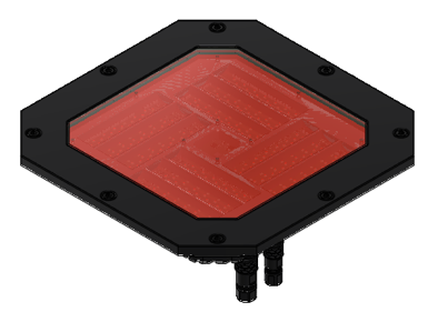
Figure: ULS-ProCopter Transmitter
A transmitter is a device placed on the ground (platform, moving object). It emits a signal in the Infrared range and serves as a kind of beacon. Transmitter marks position for drone landing.
The primary function of the transmitter is to continuously send out a coded signal that can be detected and interpreted by the receiver unit onboard the ULS-ProCopter. This signal contains critical information needed for the operation of the ULS-ProCopter, such as positional data, commands, and system status.
Receiver (Onboard Unit)
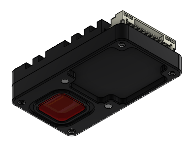
Figure: ULS-ProCopter Receiver
A receiver is a device that is placed on board an aircraft.
The receiver decodes this signal to derive flight information such as positional coordinates, real-time transmitter status updates, and landing guidance. It interprets the data to navigate accurately and ensure drone follows the intended flight path. It provides feedback to the autopilot systems, such as Ardupilot and PX4, to adjust the flight parameters as needed for optimal and safety landing or hovering above.
Part Numbering
| Part Number | Description |
|---|---|
| ULS-ProCopter | System set with 1 receiver. |
| ULS-ProCopter-MRX | System set with 2 receivers. |
| ULSDV-PC-TX | Transmitter unit. Generation 2. |
| ULSDV-PC-RX | Receiver unit. Generation 2. |
| GHR-10V-S | 10 Pin Connector for receiver. Cable side. Manufacturer, JST Commercial. |
| SA810/P8IIB | 8 Pin Connector for transmitter. Cable side. Manufacturer, Weipu Connector. |
| SA610/P4IB | 4 Pin Connector for transmitter. Cable side. Manufacturer, Weipu Connector. |
Table: ULS-ProCopter Part Numbers and Descriptions
System specification.
Common specification:
| Parameter | Value |
|---|---|
| Distance range m.: | 0.1 - 20.0 |
| Working angle (deg): | >100 |
| Data update frequency (Hz): | 20 |
Table: Common System Specifications Receiver (on board unit):
| Parameter | Value |
|---|---|
| Field of view (deg): | 100 |
| Dimensions mm : | 18.4 x 33.4 x 6.9 |
| Weight g.: | 10 |
| Power Consumption (W): | 0.3 |
| Voltage supply (V): | 5.0 |
| Interfaces: | USB, CAN, UART |
Table: Receiver Specifications Transmitter (on ground)
| Parameter | Value |
|---|---|
| Field of emitting (deg): | >100 |
| Dimensions mm. : | 183 x 183 x 29 |
| Weight g.: | 1200 |
| Power Consumption (W): | 18.4 |
| Voltage supply (V): | 12V- 27V |
| Interfaces : | USB, CAN, UART |
Table: Transmitter Specifications
Pinout information
Transmitter pinout
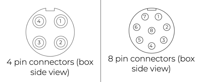
Figure: ULS-ProCopter Transmitter Pinout Diagram
| Pin number | ProCopter |
|---|---|
| 1 | Vcc Input (+12.0V..+27V) |
| 2 | CAN2 H |
| 3 | CAN2 L |
| 4 | UART TX |
| 5 | UART RX |
| 6 | USB D- |
| 7 | USB D+ |
| 8 | GND |
Table: Transmitter 8-pin Main Connector Pinout
| Pin number | ProCopter |
|---|---|
| 1 | +5V Output |
| 2 | CAN1 H |
| 3 | CAN1 L |
| 5 | GND |
Table: Transmitter 4-pin Connector Pinout
Receiver pinout
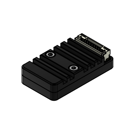
Figure: Receiver Top Side Connector Variant
Figure: Receiver Strait Variant
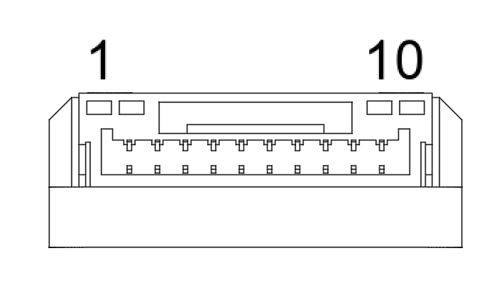
Figure: ULS-ProCopter Receiver connector
| Pin number | Strait Variant | Top Side Connector Variant |
|---|---|---|
| 1 | +5V Input | GND |
| 2 | UART RX | UART2 TX |
| 3 | UART TX | UART2 RX |
| 4 | CAN H | USB D+ |
| 5 | CAN L | USB D- |
| 6 | USB D- | CAN L |
| 7 | USB D+ | CAN H |
| 8 | UART2 RX | UART TX |
| 9 | UART2 TX | UART RX |
| 10 | GND | +5V Input |
Table: Receiver JX1 Connector Pinout (External Power and Control)
Mechanical dimensions
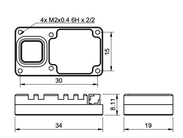
Figure: ULS-ProCopter Receiver dimensions
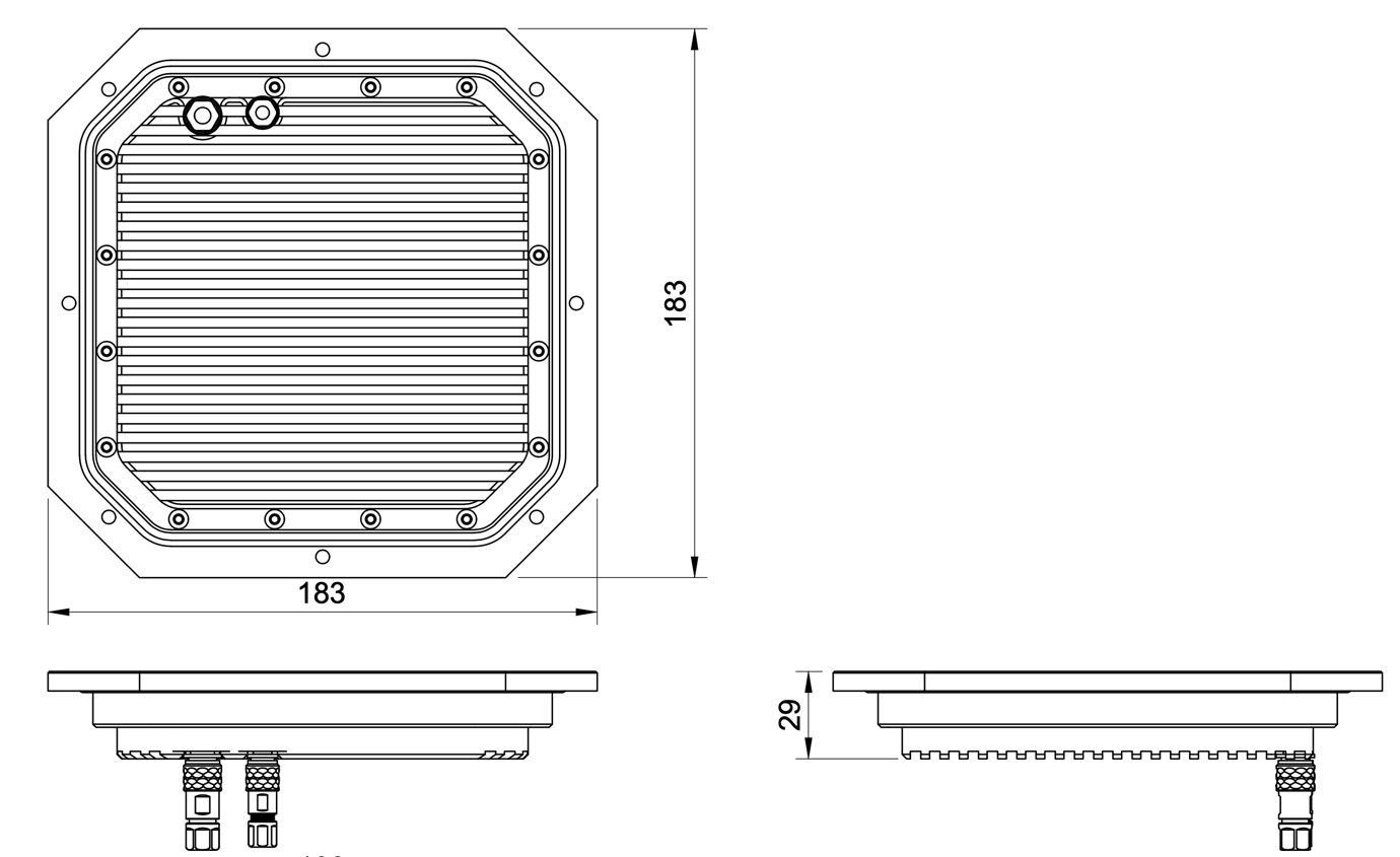
Figure: ULS-ProCopter Transmitter Mechanical Dimensions
System performance characteristics
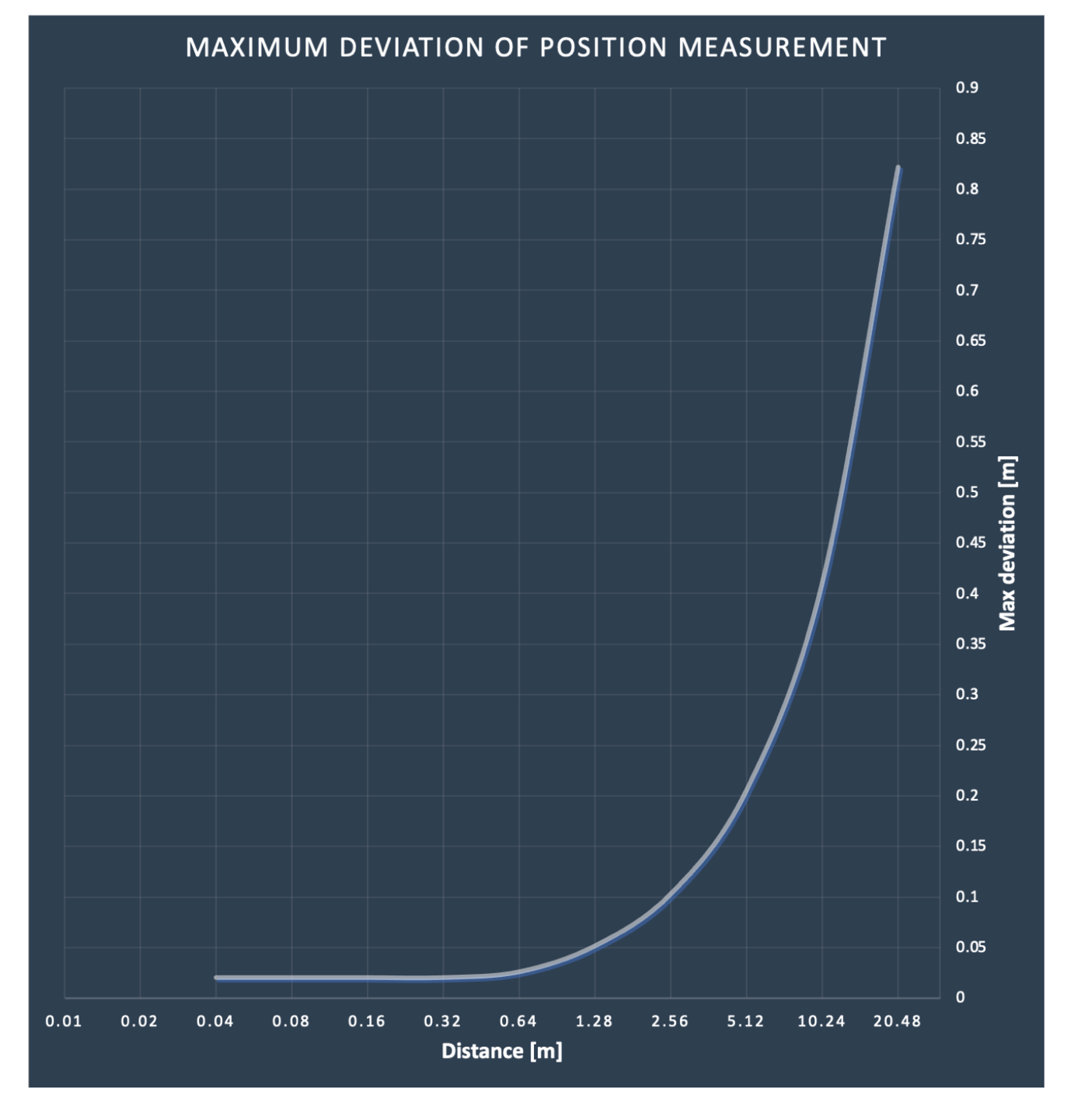
Environmental Conditions - Industrial Grade
Equipment is designed to operate reliably in demanding environmental conditions typical of aerospace, industrial automation, and outdoor applications.
Operating Temperature Range
- Standard operating range: -20°C to +55°C
- Covers most industrial and outdoor applications
- Reliable performance across temperature extremes
- No performance degradation within specified range
Humidity Tolerance
- Relative humidity: Up to 70% (non-condensing)
- Protected against moisture in typical operating conditions
- Suitable for outdoor and semi-protected installations
- Condensation prevention through sealed design
Ingress Protection
- IP67 rated (Dust tight and water immersion resistant)
- 6 - Complete protection against dust ingress
- 7 - Protected against temporary immersion in water (up to 1 meter depth for 30 minutes)
- Suitable for harsh industrial environments
- Protected against rain, splashing, and temporary submersion
- Dust-tight sealing for contaminated environments
Storage Conditions
- Storage temperature: -40°C to +70°C
- Relative humidity: Up to 95% (non-condensing)
- Long-term storage in industrial facilities
Operational Environment Standards
- Designed to meet industrial equipment requirements
- Suitable for UAV/drone applications
- Outdoor installation capable
- Protected against:
- Dust and particulate matter
- Water spray and rain
- Temporary water immersion
- Temperature fluctuations
- High humidity
Change Control
All changes to this document must be reviewed and approved by the relevant technical leads and stakeholders