ULS-ProCopter-G3 Datasheet
ULSDC-PBDS271026 · version 0.2.0 · issued November 8, 2026
The numbered PDF is the controlled copy: download it from the portal.
Introduction
Purpose
The purpose of this datasheet is to provide comprehensive technical information about the ULS-ProCopter-G3 system family. This includes specifications, performance characteristics, and detailed descriptions of system components, such as transmitters and receivers. By outlining the interfaces between these components, the datasheet aims to facilitate seamless integration and operation for system engineers, integrators, and developers working with ULS-ProCopter-G3 systems.
Scope
This document is intended for use by system engineers, integrators, and developers working with ULS-ProCopter-G3 systems. It provides detailed information on the system.
Product Overview
ULS-ProCopter-G3 is the third generation of the ULS-ProCopter precision landing system for VTOL drones: a ruggedized system with an IP67 transmitter for industrial use. It keeps the architecture of the previous generation — one ground transmitter and one or two onboard receivers — and adds DACS (Distance and Azimuth Correction System) support for more accurate yaw orientation of the vehicle relative to the transmitter.
Key Features
- DACS (Distance and Azimuth Correction System) for improved yaw orientation in compass and MRX modes
- Optical transmitter-to-receiver link, free of radio interference
- IP67 dust- and waterproof transmitter for harsh environments and industrial applications
- Single receiver or dual receiver (MRX) configuration
- USB, CAN and RS-422 on the transmitter; USB, CAN and UART on the receiver; MAVLink 2 integration with ArduPilot and PX4
System Base Components
Transmitter (Ground Unit)
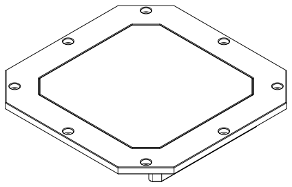
Figure: ULSDV-PC-G3-TX Transmitter
A transmitter is a device placed on the ground (platform, moving object). It emits a signal in the infrared range and serves as a kind of beacon. The transmitter marks the position for drone landing.
The primary function of the transmitter is to continuously send out a coded signal that can be detected and interpreted by the receiver unit on board. This signal contains the information the receiver needs to operate: positional data, DACS correction data, commands, and system status.
Receiver (Onboard Unit)
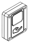
Figure: ULSDV-PC-G3-RX Receiver
A receiver is a device that is placed on board an aircraft.
The receiver decodes the transmitter signal to derive flight information such as positional coordinates, real-time transmitter status updates, DACS yaw correction, and landing guidance. It provides this information to the autopilot (ArduPilot, PX4 and similar), which adjusts the flight parameters for a precise and safe landing or hover.
Distance and Azimuth Correction System (DACS)
ULS-ProCopter-G3 adds DACS (Distance and Azimuth Correction System) support. In addition to the positioning signal, the transmitter emits a dedicated DACS stage in every frame. The receiver uses it to calculate its YAW orientation relative to the transmitter more accurately.
DACS is an aid to the existing ways of finding the mutual orientation of the transmitter and the vehicle:
- Compass mode — DACS corrects the heading derived from the ground unit compass and the autopilot compass, reducing the effect of compass calibration errors and local magnetic interference.
- MRX mode — DACS supports the yaw calculated from two receivers by the triangular method.
DACS provides:
- Yaw orientation — heading of the vehicle relative to the transmitter.
- Azimuth data — directional angle information for approach guidance.
- Distance correction — improved distance measurement accuracy.
DACS is enabled or disabled per receiver with the disable_dacs_yaw_correction setting in ULSToolsX (UTX). Over CAN, DACS data is available in the ULS-Blitz RX_DACS (0x0014) message.
Part Numbering
| Part Number | Description |
|---|---|
| ULS-ProCopter-G3 | System set with 1 receiver. |
| ULS-ProCopter-G3-MRX | System set with 2 receivers. |
| ULSDV-PC-G3-TX | Transmitter unit. Generation 3. |
| ULSDV-PC-G3-RX | Receiver unit. Generation 3. |
| GHR-10V-S | 10 Pin Connector for receiver. Cable side. Manufacturer, JST Commercial. |
| SA810/P8IIB | 8 Pin Connector for transmitter. Cable side. Manufacturer, Weipu Connector. |
| SA610/P4IB | 4 Pin Connector for transmitter. Cable side. Manufacturer, Weipu Connector. |
Table: ULS-ProCopter-G3 Part Numbers and Descriptions
System Specification
Common specification:
| Parameter | Value |
|---|---|
| Distance range m.: | 0.1 - 20.0 |
| Working angle (deg): | >100 |
| Data update frequency (Hz): | 20 |
| Yaw correction: | DACS |
Table: Common System Specifications Receiver (on board unit):
| Parameter | Value |
|---|---|
| Field of view (deg): | 100 |
| Dimensions mm : | 30 x 34 x 10 |
| Weight g.: | 20 |
| Power Consumption (W): | 0.3 |
| Voltage supply (V): | 5.0 |
| Interfaces: | USB, CAN, UART |
Table: Receiver Specifications Transmitter (on ground)
| Parameter | Value |
|---|---|
| Field of emitting (deg): | >100 |
| Dimensions mm. : | 183 x 183 x 29.8 |
| Weight g.: | 1200 |
| Power Consumption (W): | 18.4 |
| Voltage supply (V): | 12V- 27V |
| Interfaces : | USB, CAN, RS-422 |
Table: Transmitter Specifications
Pinout Information
Transmitter Pinout

Figure: ULSDV-PC-G3-TX Transmitter Connector Side
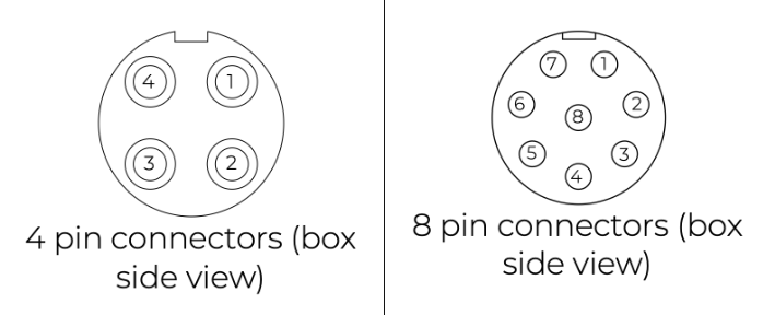
Figure: ULSDV-PC-G3-TX Transmitter Pinout Diagram
| Pin number | Signal |
|---|---|
| 1 | Vext (+12.0V..+27V) |
| 2 | RS-422 RX+ |
| 3 | RS-422 RX- |
| 4 | RS-422 TX+ |
| 5 | RS-422 TX- |
| 6 | CAN1 L |
| 7 | CAN1 H |
| 8 | GND |
Table: Transmitter 8-pin Connector J3 Pinout (SA812-S8B-PS0.6)
| Pin number | Signal |
|---|---|
| 1 | Vext (+12.0V..+27V) |
| 2 | CAN2 L |
| 3 | CAN2 H |
| 4 | GND |
Table: Transmitter 4-pin Connectors J1 and J2 Pinout (SA612-S4B-PS0.6)
Receiver Pinout
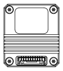
Figure: ULSDV-PC-G3-RX Receiver Rear View, Connector Side
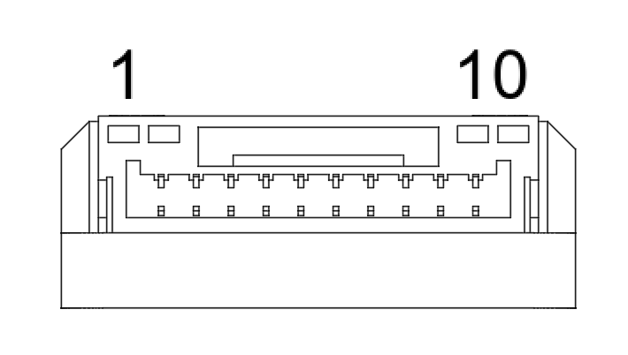
Figure: ULSDV-PC-G3-RX Receiver Connector
| Pin number | Signal |
|---|---|
| 1 | +5V Input |
| 2 | UART RX |
| 3 | UART TX |
| 4 | CAN H |
| 5 | CAN L |
| 6 | USB D- |
| 7 | USB D+ |
| 8 | UART2 RX |
| 9 | UART2 TX |
| 10 | GND |
Table: Receiver 10-pin Connector Pinout
Mechanical Dimensions
Receiver: 30 x 34 x 10 mm including the connector (body thickness 9 mm), weight 20 g.
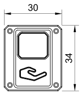
Figure: ULSDV-PC-G3-RX Receiver Front View, Dimensions in mm
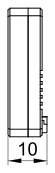
Figure: ULSDV-PC-G3-RX Receiver Side View, Dimensions in mm
Transmitter: 183 x 183 x 29.8 mm, weight 1.2 kg.
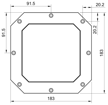
Figure: ULSDV-PC-G3-TX Transmitter Front View, Dimensions in mm
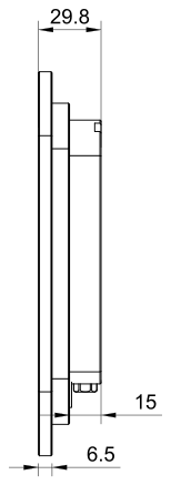
Figure: ULSDV-PC-G3-TX Transmitter Side View, Dimensions in mm
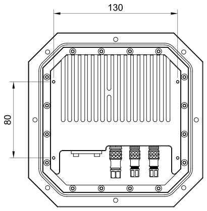
Figure: ULSDV-PC-G3-TX Transmitter Rear View, Dimensions in mm
System Performance Characteristics
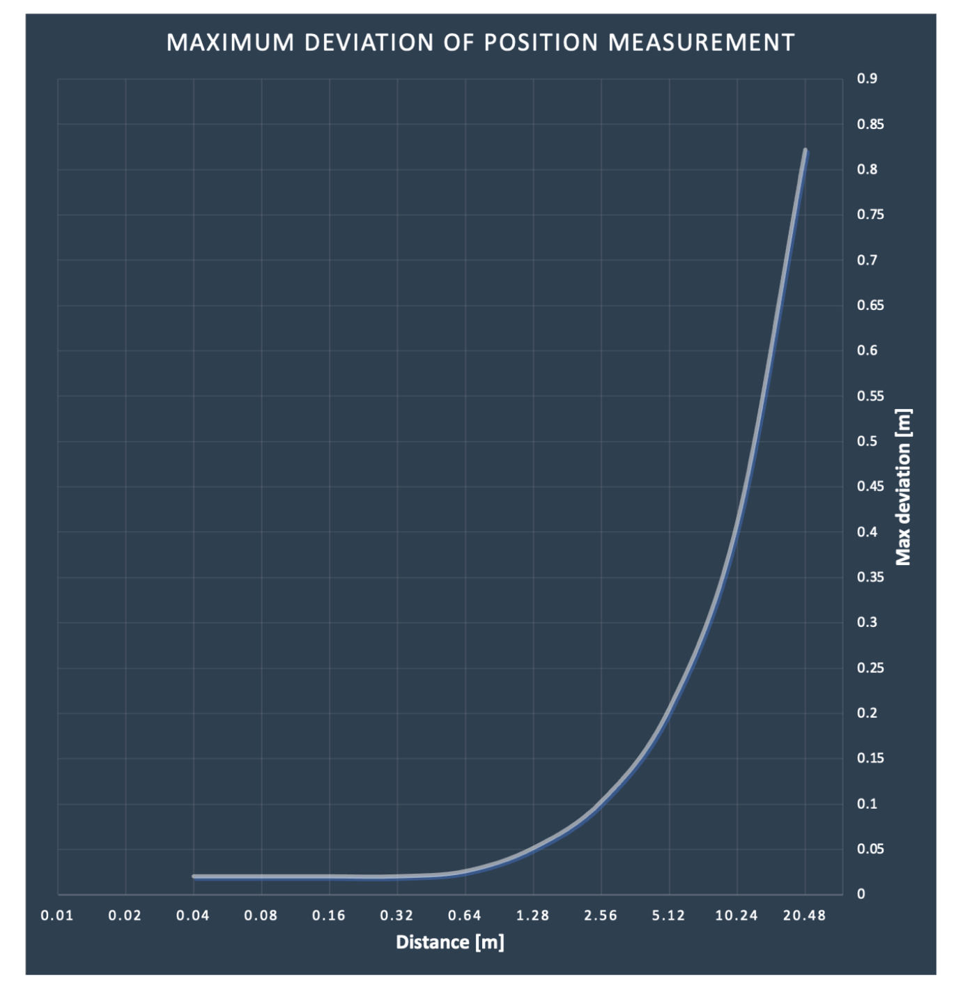
Figure: System Performance Characteristics
Environmental Conditions - Industrial Grade
Equipment is designed to operate reliably in demanding environmental conditions typical of aerospace, industrial automation, and outdoor applications.
Operating Temperature Range
- Standard operating range: -20°C to +55°C
- Covers most industrial and outdoor applications
- Reliable performance across temperature extremes
- No performance degradation within specified range
Humidity Tolerance
- Relative humidity: Up to 70% (non-condensing)
- Protected against moisture in typical operating conditions
- Suitable for outdoor and semi-protected installations
- Condensation prevention through sealed design
Ingress Protection
- IP67 rated (Dust tight and water immersion resistant)
- 6 - Complete protection against dust ingress
- 7 - Protected against temporary immersion in water (up to 1 meter depth for 30 minutes)
- Suitable for harsh industrial environments
- Protected against rain, splashing, and temporary submersion
- Dust-tight sealing for contaminated environments
Storage Conditions
- Storage temperature: -40°C to +70°C
- Relative humidity: Up to 95% (non-condensing)
- Long-term storage in industrial facilities
Operational Environment Standards
- Designed to meet industrial equipment requirements
- Suitable for UAV/drone applications
- Outdoor installation capable
- Protected against:
- Dust and particulate matter
- Water spray and rain
- Temporary water immersion
- Temperature fluctuations
- High humidity
Optical Radiation Safety (IR Emission)
The transmitter (ground unit) emits pulsed infrared optical radiation with a centre wavelength of 940nm. The receivers are optical sensors only and do not emit optical radiation.
Why This Warning Is Given
Radiation at 940nm is outside the visible range. The protective mechanisms that limit exposure to bright visible sources — the blink reflex, pupil constriction, and the instinct to look away — are not triggered by an invisible source. Exposure time is therefore limited only by operator behaviour, which is why the precautions below are given as operating instructions and not left to the operator’s judgement.
The transmitter is a positioning beacon. It is not an illumination product and is not intended to be viewed at any time.
Operating Precautions
- Do not look directly into the transmitter emitter apertures from a distance of less than 1 metre while the unit is powered.
- Treat the transmitter as emitting whenever supply voltage is applied, including when no receiver is present and no positioning data is being transferred.
- Switch emission off before working directly in front of the transmitter. Use the Illumination parameter in ULS-Tools to disable emission, or disconnect supply power.
- Do not view the powered transmitter through binoculars, telescopes, camera lenses, magnifiers, or any other light-collecting instrument. Such optics concentrate the emission and can raise the exposure at the eye by orders of magnitude compared with unaided viewing.
- Do not add, remove, or modify optical elements of the transmitter. Added optics change the emission characteristics and invalidate any photobiological classification of the unit.
- Position the transmitter so that the emission field is directed away from work positions and walkways where personnel stay for extended periods.
- Servicing personnel working inside the emission field at close range should disable emission first rather than rely on viewing distance.
Classification and Applicable Standards
| Item | Value |
|---|---|
| Emitter type | Incoherent IR LED array (not a laser) |
| Centre wavelength | 940nm |
| Emission mode | Pulsed |
| Applicable standard | IEC 62471 / EN 62471, Photobiological safety of lamps and lamp systems |
| Classification distance | 200mm (non-GLS source, per IEC 62471) |
| Risk group | TBD — to be entered from the IEC 62471 assessment report |
| Hazard distance | TBD — to be entered from the IEC 62471 assessment report |
Table: Optical Radiation Safety Data
For a 940nm source the applicable exposure limits are the retinal thermal hazard (380nm to 1400nm), the retinal thermal hazard for a weak visual stimulus (780nm to 1400nm, which applies specifically to sources that give no visual cue), and the infrared hazard to the cornea and lens (780nm to 3000nm). The corneal and lens limits are intended for chronic exposures longer than 1000s at a daily averaged irradiance of 100 W/m² or more.
Organisations operating this equipment within the European Union are additionally subject to Directive 2006/25/EC on the exposure of workers to artificial optical radiation, which requires the employer to assess worker exposure against the exposure limit values given in Annex I of that directive. UAVLAS provides the emission data needed for that assessment on request.
Change Control
All changes to this document must be reviewed and approved by the relevant technical leads and stakeholders