ULS-ProCopter-G3 Operation Manual
ULSDC-PBOM271026 · version 0.2.0 · issued November 8, 2026
The numbered PDF is the controlled copy: download it from the portal.
Introduction
Purpose
The purpose of this operation manual is to provide comprehensive guidance on the installation, configuration, operation, and troubleshooting of the ULS-ProCopter-G3 system. This manual is designed to help users effectively integrate and utilize the system for precision landing and navigation applications.
Scope
This document is intended for use by system engineers, integrators, operators, and developers working with ULS-ProCopter-G3 systems. It provides detailed information on system operation, configuration procedures, and integration with autopilot systems.
Safety Information
- WARNING: The transmitter emits invisible infrared radiation when powered. Do not look into the emitter apertures at close range. See the Optical Radiation Safety section below.
- CAUTION: Do not connect or disconnect the transmitter cable under power.
Optical Radiation Safety (IR Emission)
The transmitter (ground unit) emits pulsed infrared optical radiation with a centre wavelength of 940nm. The receivers are optical sensors only and do not emit optical radiation.
Why This Warning Is Given
Radiation at 940nm is outside the visible range. The protective mechanisms that limit exposure to bright visible sources — the blink reflex, pupil constriction, and the instinct to look away — are not triggered by an invisible source. Exposure time is therefore limited only by operator behaviour, which is why the precautions below are given as operating instructions and not left to the operator’s judgement.
The transmitter is a positioning beacon. It is not an illumination product and is not intended to be viewed at any time.
Operating Precautions
- Do not look directly into the transmitter emitter apertures from a distance of less than 1 metre while the unit is powered.
- Treat the transmitter as emitting whenever supply voltage is applied, including when no receiver is present and no positioning data is being transferred.
- Switch emission off before working directly in front of the transmitter. Use the Illumination parameter in ULS-Tools to disable emission, or disconnect supply power.
- Do not view the powered transmitter through binoculars, telescopes, camera lenses, magnifiers, or any other light-collecting instrument. Such optics concentrate the emission and can raise the exposure at the eye by orders of magnitude compared with unaided viewing.
- Do not add, remove, or modify optical elements of the transmitter. Added optics change the emission characteristics and invalidate any photobiological classification of the unit.
- Position the transmitter so that the emission field is directed away from work positions and walkways where personnel stay for extended periods.
- Servicing personnel working inside the emission field at close range should disable emission first rather than rely on viewing distance.
Classification and Applicable Standards
| Item | Value |
|---|---|
| Emitter type | Incoherent IR LED array (not a laser) |
| Centre wavelength | 940nm |
| Emission mode | Pulsed |
| Applicable standard | IEC 62471 / EN 62471, Photobiological safety of lamps and lamp systems |
| Classification distance | 200mm (non-GLS source, per IEC 62471) |
| Risk group | TBD — to be entered from the IEC 62471 assessment report |
| Hazard distance | TBD — to be entered from the IEC 62471 assessment report |
Table: Optical Radiation Safety Data
For a 940nm source the applicable exposure limits are the retinal thermal hazard (380nm to 1400nm), the retinal thermal hazard for a weak visual stimulus (780nm to 1400nm, which applies specifically to sources that give no visual cue), and the infrared hazard to the cornea and lens (780nm to 3000nm). The corneal and lens limits are intended for chronic exposures longer than 1000s at a daily averaged irradiance of 100 W/m² or more.
Organisations operating this equipment within the European Union are additionally subject to Directive 2006/25/EC on the exposure of workers to artificial optical radiation, which requires the employer to assess worker exposure against the exposure limit values given in Annex I of that directive. UAVLAS provides the emission data needed for that assessment on request.
System Base Components
Transmitter (Ground Unit)
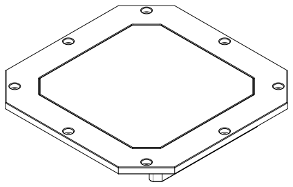
Figure: ULSDV-PC-G3-TX Transmitter
A transmitter is a device placed on the ground (platform, moving object). It emits a signal in the infrared range and serves as a kind of beacon. The transmitter marks the position for drone landing.
The primary function of the transmitter is to continuously send out a coded signal that can be detected and interpreted by the receiver unit on board. This signal contains the information the receiver needs to operate: positional data, DACS correction data, commands, and system status.
Receiver (Onboard Unit)
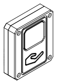
Figure: ULSDV-PC-G3-RX Receiver
A receiver is a device that is placed on board an aircraft.
The receiver decodes the transmitter signal to derive flight information such as positional coordinates, real-time transmitter status updates, DACS yaw correction, and landing guidance. It provides this information to the autopilot (ArduPilot, PX4 and similar), which adjusts the flight parameters for a precise and safe landing or hover.
Operation Theory
All data communication from the transmitter to the receiver is done in the optical band, which eliminates interference with other radio devices and radio signals.
The transmitter contains an array of emitting elements that operate in the infrared range. The transmitter emits a modulated signal with each of the transmitter emitters transmitting a unique signal. Each of the transmitter emitters emits in a unique direction. The receiver receives the signal from the transmitter, decodes it, and by analyzing the signal can determine in which direction relative to the transmitter it is located. The distance to the transmitter is determined by the signal strength. Thus the system determines the position in a polar coordinate system with the origin at the center of the transmitter.
Due to the features described above, the receiver position readings change when the transmitter orientation is changed, but a change in receiver orientation has no effect while the transmitter and receiver are within the range of visibility given in the specification.
This must be taken into account when working with the system. In order to calculate the position of the receiver without errors in case of orientation changes, the transmitter is equipped with an inertial orientation measurement system. This system determines the orientation of the module and transmits this information to the receiver by means of the infrared signal, so that the receiver can correct the position according to the inclination of the transmitter (transmitter level correction function).
The system then converts the polar coordinate system to a Cartesian coordinate system with its origin at the center of the transmitter.
To navigate and ensure a precise landing, the autopilot needs information about the position of the landing point in a coordinate system either attached to the drone’s body or in a global coordinate system. For this purpose, the receiver requests information from the autopilot about its position and orientation. Then, using this information and information about the orientation of the ground transmitter, the receiver can calculate the position of the transmitter relative to the drone in the required coordinates.
Distance and Azimuth Correction System (DACS)
ULS-ProCopter-G3 adds DACS (Distance and Azimuth Correction System) support. In addition to the positioning signal, the transmitter emits a dedicated DACS stage in every frame. The receiver uses it to calculate its YAW orientation relative to the transmitter more accurately.
DACS is an aid to the existing ways of finding the mutual orientation of the transmitter and the vehicle:
- Compass mode — DACS corrects the heading derived from the ground unit compass and the autopilot compass, reducing the effect of compass calibration errors and local magnetic interference.
- MRX mode — DACS supports the yaw calculated from two receivers by the triangular method.
DACS provides:
- Yaw orientation — heading of the vehicle relative to the transmitter.
- Azimuth data — directional angle information for approach guidance.
- Distance correction — improved distance measurement accuracy.
DACS is enabled or disabled per receiver with the disable_dacs_yaw_correction setting in ULSToolsX (UTX). Over CAN, DACS data is available in the ULS-Blitz RX_DACS (0x0014) message.
System Applications
The system acts as a navigation sensor. The information from the system can be used by autopilots and drones for various purposes:
- Landing vehicle on platform
- Hovering over a point of interest
- Accurately dropping a load or precisely lowering it on a tether
Functional Description Diagram
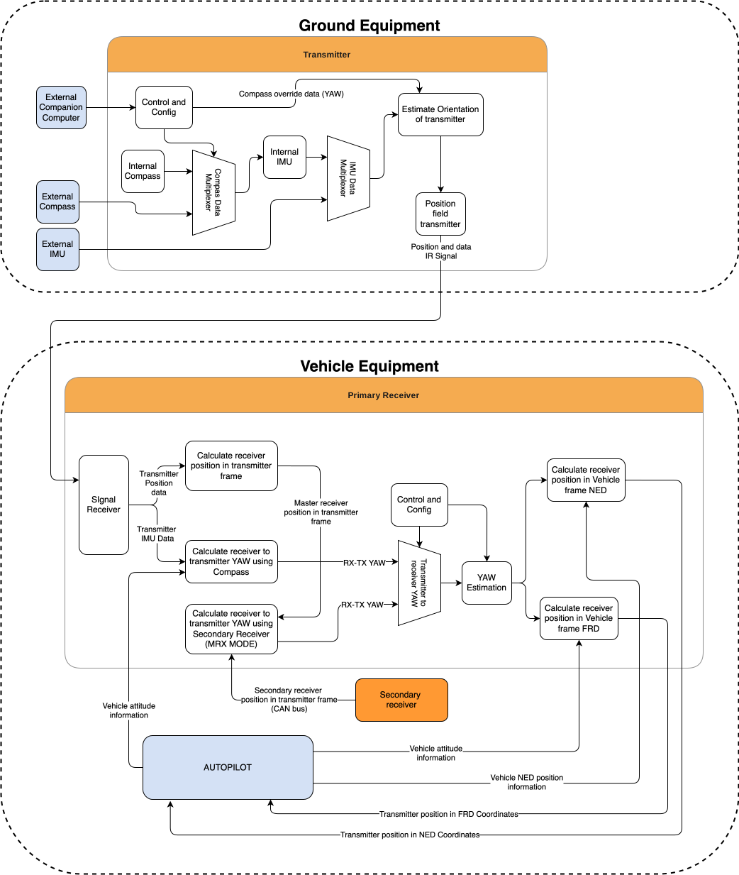
Figure: ULS-ProCopter-G3 Functional Description Diagram
System Specification
Common specification:
| Parameter | Value |
|---|---|
| Distance range m.: | 0.1 - 20.0 |
| Working angle (deg): | >100 |
| Data update frequency (Hz): | 20 |
| Yaw correction: | DACS |
Table: Common System Specifications Receiver (on board unit):
| Parameter | Value |
|---|---|
| Field of view (deg): | 100 |
| Dimensions mm : | 30 x 34 x 10 |
| Weight g.: | 20 |
| Power Consumption (W): | 0.3 |
| Voltage supply (V): | 5.0 |
| Interfaces: | USB, CAN, UART |
Table: Receiver Specifications Transmitter (on ground)
| Parameter | Value |
|---|---|
| Field of emitting (deg): | >100 |
| Dimensions mm. : | 183 x 183 x 29.8 |
| Weight g.: | 1200 |
| Power Consumption (W): | 18.4 |
| Voltage supply (V): | 12V- 27V |
| Interfaces : | USB, CAN, RS-422 |
Table: Transmitter Specifications
Pinout Information
Transmitter Pinout

Figure: ULSDV-PC-G3-TX Transmitter Connector Side
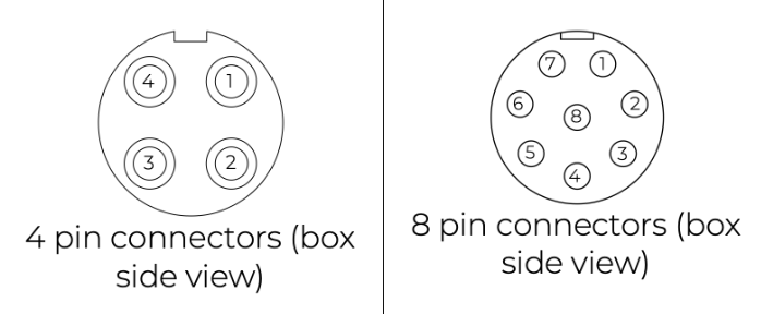
Figure: ULSDV-PC-G3-TX Transmitter Pinout Diagram
| Pin number | Signal |
|---|---|
| 1 | Vext (+12.0V..+27V) |
| 2 | RS-422 RX+ |
| 3 | RS-422 RX- |
| 4 | RS-422 TX+ |
| 5 | RS-422 TX- |
| 6 | CAN1 L |
| 7 | CAN1 H |
| 8 | GND |
Table: Transmitter 8-pin Connector J3 Pinout (SA812-S8B-PS0.6)
| Pin number | Signal |
|---|---|
| 1 | Vext (+12.0V..+27V) |
| 2 | CAN2 L |
| 3 | CAN2 H |
| 4 | GND |
Table: Transmitter 4-pin Connectors J1 and J2 Pinout (SA612-S4B-PS0.6)
Receiver Pinout
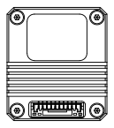
Figure: ULSDV-PC-G3-RX Receiver Rear View, Connector Side
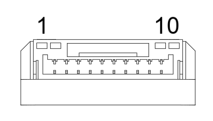
Figure: ULSDV-PC-G3-RX Receiver Connector
| Pin number | Signal |
|---|---|
| 1 | +5V Input |
| 2 | UART RX |
| 3 | UART TX |
| 4 | CAN H |
| 5 | CAN L |
| 6 | USB D- |
| 7 | USB D+ |
| 8 | UART2 RX |
| 9 | UART2 TX |
| 10 | GND |
Table: Receiver 10-pin Connector Pinout
Mechanical Dimensions
Receiver: 30 x 34 x 10 mm including the connector (body thickness 9 mm), weight 20 g.
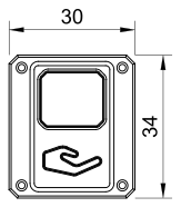
Figure: ULSDV-PC-G3-RX Receiver Front View, Dimensions in mm
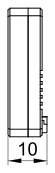
Figure: ULSDV-PC-G3-RX Receiver Side View, Dimensions in mm
Transmitter: 183 x 183 x 29.8 mm, weight 1.2 kg.
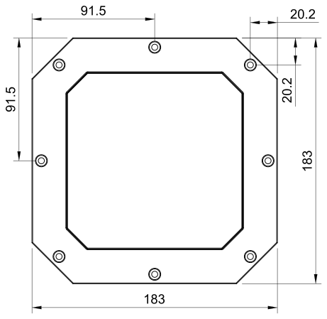
Figure: ULSDV-PC-G3-TX Transmitter Front View, Dimensions in mm
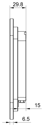
Figure: ULSDV-PC-G3-TX Transmitter Side View, Dimensions in mm
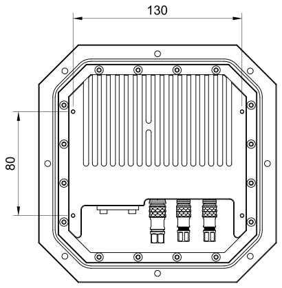
Figure: ULSDV-PC-G3-TX Transmitter Rear View, Dimensions in mm
Installation and Configuration
Setup Software: ULSToolsX (UTX)
ULS-ProCopter-G3 is set up with ULSToolsX (UTX). Use it to connect to the transmitter and receivers, read their live status, change and save their settings, and update their firmware. UTX replaces ULS-Tools: where a shared section of this manual mentions ULS-Tools, use UTX for this product.
This manual describes only the ULS-ProCopter-G3 settings. For how to use the application, see the ULSToolsX User Manual (ULSDC-PBUM021126). It covers installation, connecting, changing settings, updating firmware and reading each dashboard widget. The web version of UTX is at utx.tools.uavlas.com.
To connect a device:
- Connect the device to a USB port of the computer: the receiver through the USB pins of its connector, the transmitter through its USB-C port.
- On the Serial card of the connection page, select the port.
- Select the device in the device list. Other devices on the same CAN bus appear in the list too, and you can set them up over the same link.
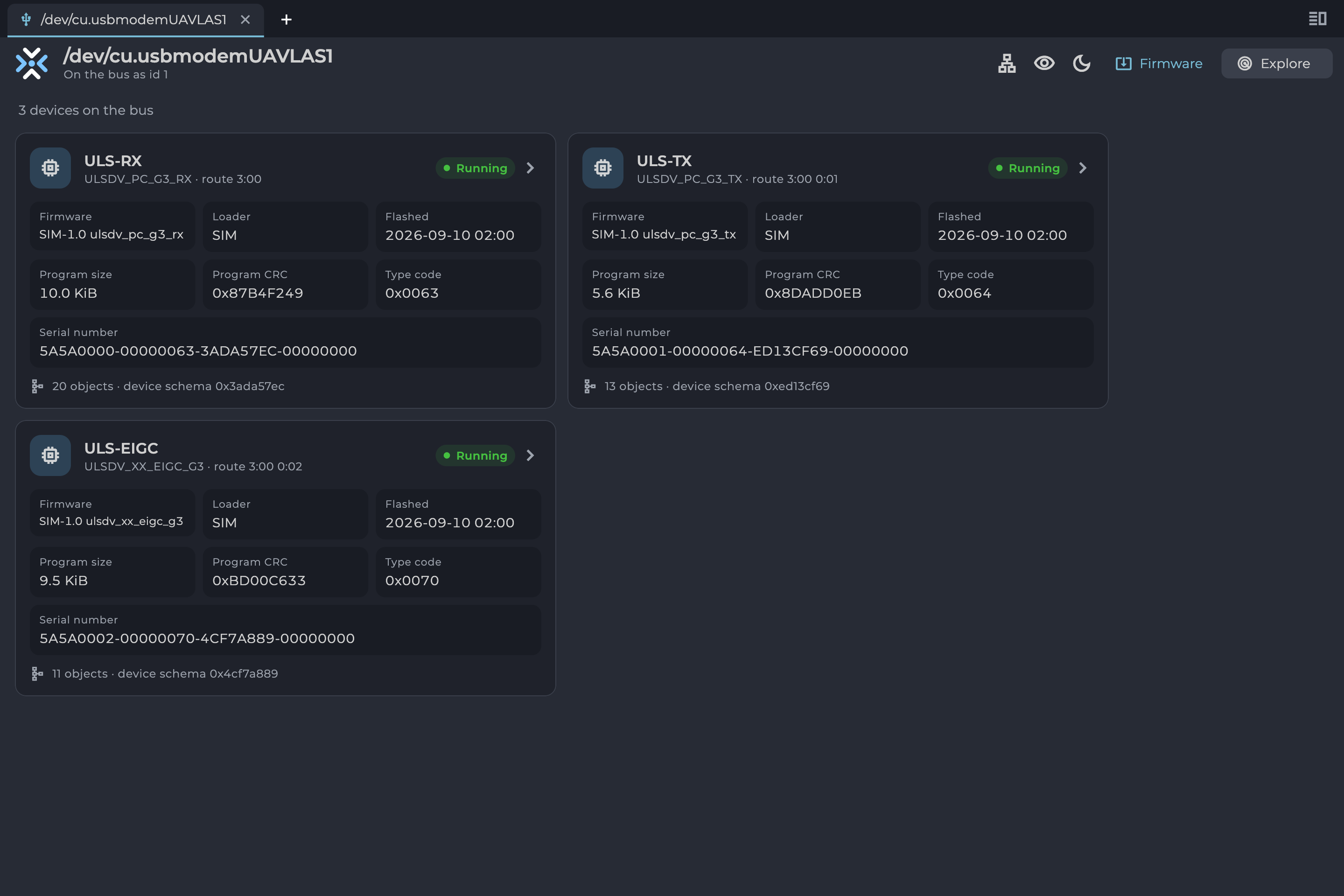
Figure: UTX Device List
To change a setting, open the device’s Config tab and change the value. Select Write to send it to the device, then Save to flash to keep it after a power cycle. The settings available depend on the user level chosen in the app bar; the tables below give the level each setting needs.
Ground Unit Installation (Transmitter)
The device must be installed on a clean surface in an open area. There must be no obstacles in the radiation field of the transmitting device. If possible, avoid installing the system near vertical surfaces that can strongly reflect infrared radiation. The device is designed to be installed in a panel and bolted with M4 screws. All customers receive a 3D model of the system and a panel cut-out as a reference to make integration simpler.
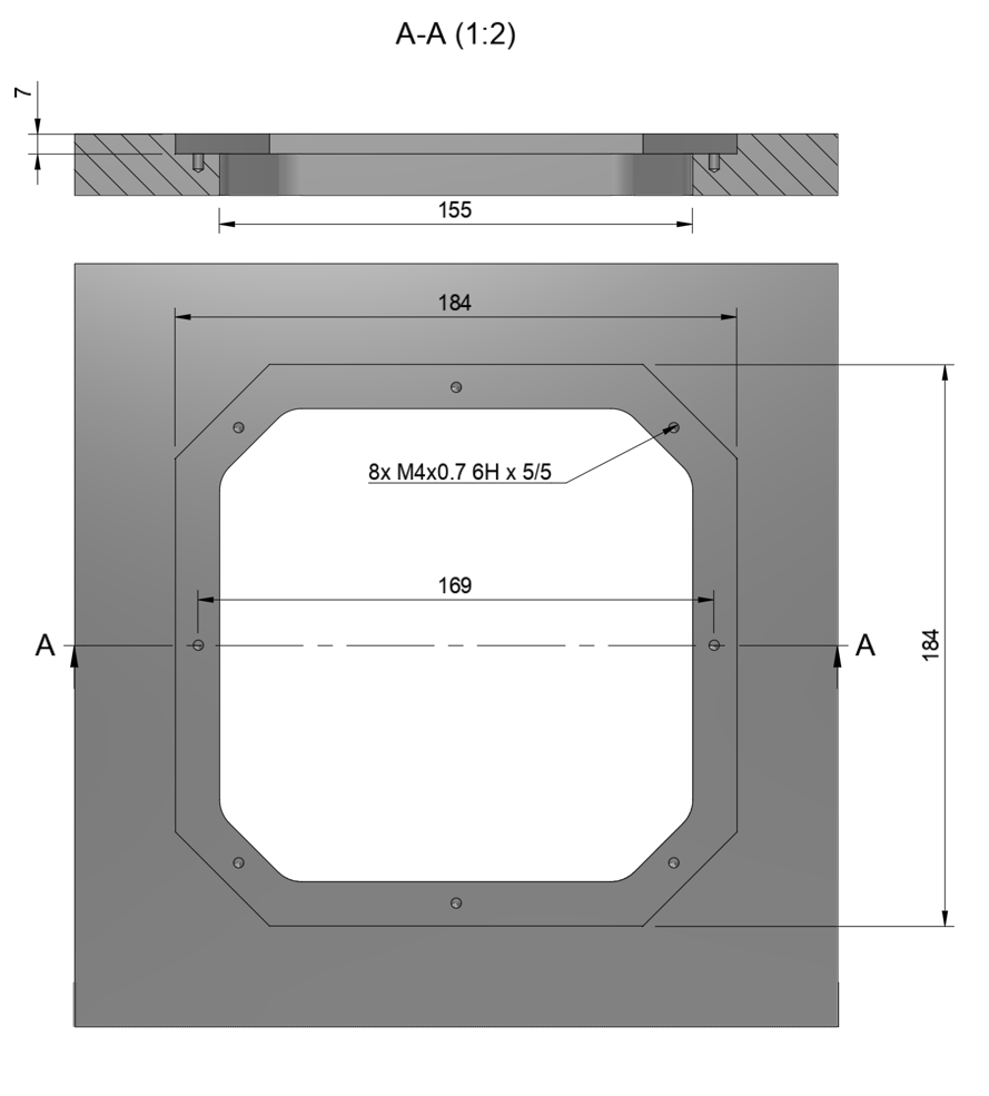
Figure: Transmitter Panel Cut-out Drawing
After installation, it is recommended to verify the correctness of the compass reading and, if necessary, correct the compass calibration.
Wiring Transmitter
The transmitter only requires power to operate. It is powered through the Vext and GND pins. External compass (IMU) and control data can be sent over RS-422 and CAN. See the transmitter pinout information.
Configure Transmitter in UTX
Open the transmitter in the device list and select its Config tab.
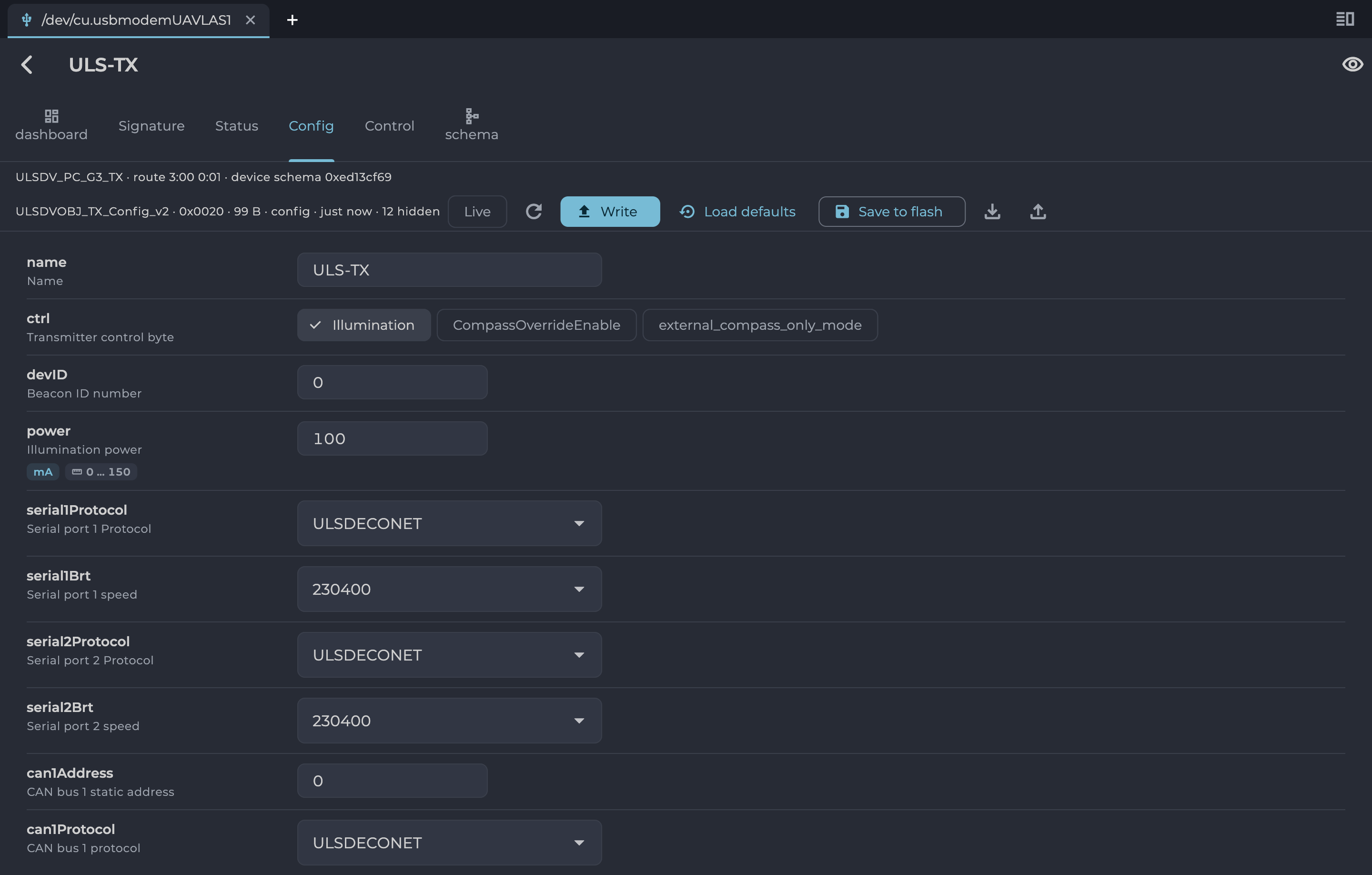
Figure: UTX Transmitter Configuration
| Setting | Level | Description |
|---|---|---|
| name | Normal | Name of the device shown in the device list. |
| ctrl: Illumination | Normal | Enables the emitters. Disable it to configure the transmitter without emission. |
| ctrl: CompassOverrideEnable | Normal | Enable if the transmitter is installed on a fixed platform. The value of cpsOverride is then used instead of internal compass data, and the transmitter must be turned to that angle, clockwise from North. |
| ctrl: external_compass_only_mode | Normal | If enabled, the system does not use the internal compass and reports an error when external compass data is unavailable. If disabled, the internal compass is used when the external one is unavailable. |
| devID | Normal | Beacon ID number. |
| power | Normal | Illumination power, in mA. |
| indicatorBrightness | Normal | Brightness of the RGB LED indicator, in %. |
| serial1Protocol, serial2Protocol | Normal | Protocol of the serial port. |
| serial1Brt, serial2Brt | Normal | Speed of the serial port. |
| can1Address, can2Address | Normal | Static address on the CAN bus. |
| can1Protocol, can2Protocol | Normal | Protocol of the CAN bus. |
| can1Speed, can2Speed | Normal | Speed of the CAN bus. |
| Vlow | Advanced | Voltage at which the indicator starts the low voltage warning. |
| Voff | Advanced | Voltage at which the emitters are disabled, to prevent battery under-discharge. |
| serial1Options, serial2Options | Advanced | Serial port options: receive and transmit enable, termination and inversion. |
| can1Options, can2Options | Advanced | CAN bus termination. |
| cpsOverride | Service | Compass angle used when CompassOverrideEnable is set, in degrees. |
| magCalOffset, magCalScale | Service | Calibration of the internal magnetometer. Set by compass calibration. |
| magCalOffsetEx, magCalScaleEx | Service | Calibration of the external magnetometer. |
Table: Transmitter Configuration Settings
Compass Calibration
The compass is used to calculate the absolute heading of the ground unit. This information is transmitted to the receiver and used to calculate NED coordinates. The compass must be calibrated before use. Use the Compass calibration card on the transmitter’s dashboard tab:
- Select Recalibrate and confirm.
- Rotate the device in different directions until the points form a circle in each of the 3 plots.
- Select Apply to write the new calibration to the device.
- Select Save to flash and confirm.
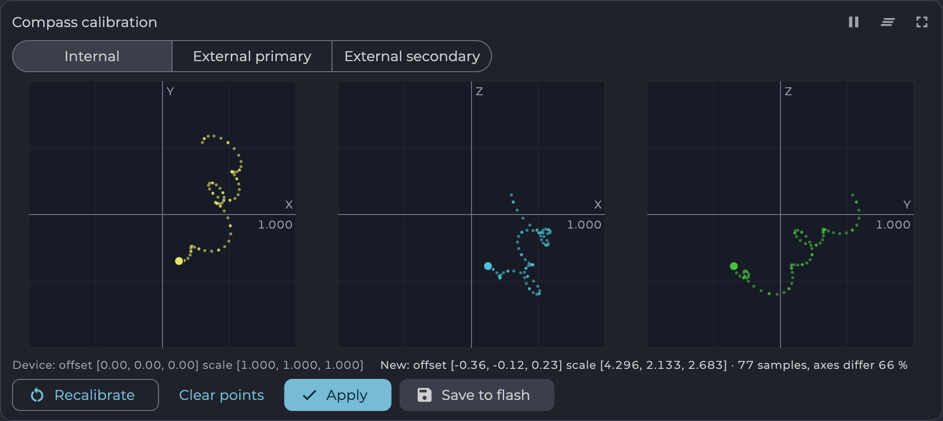
Figure: UTX Compass Calibration
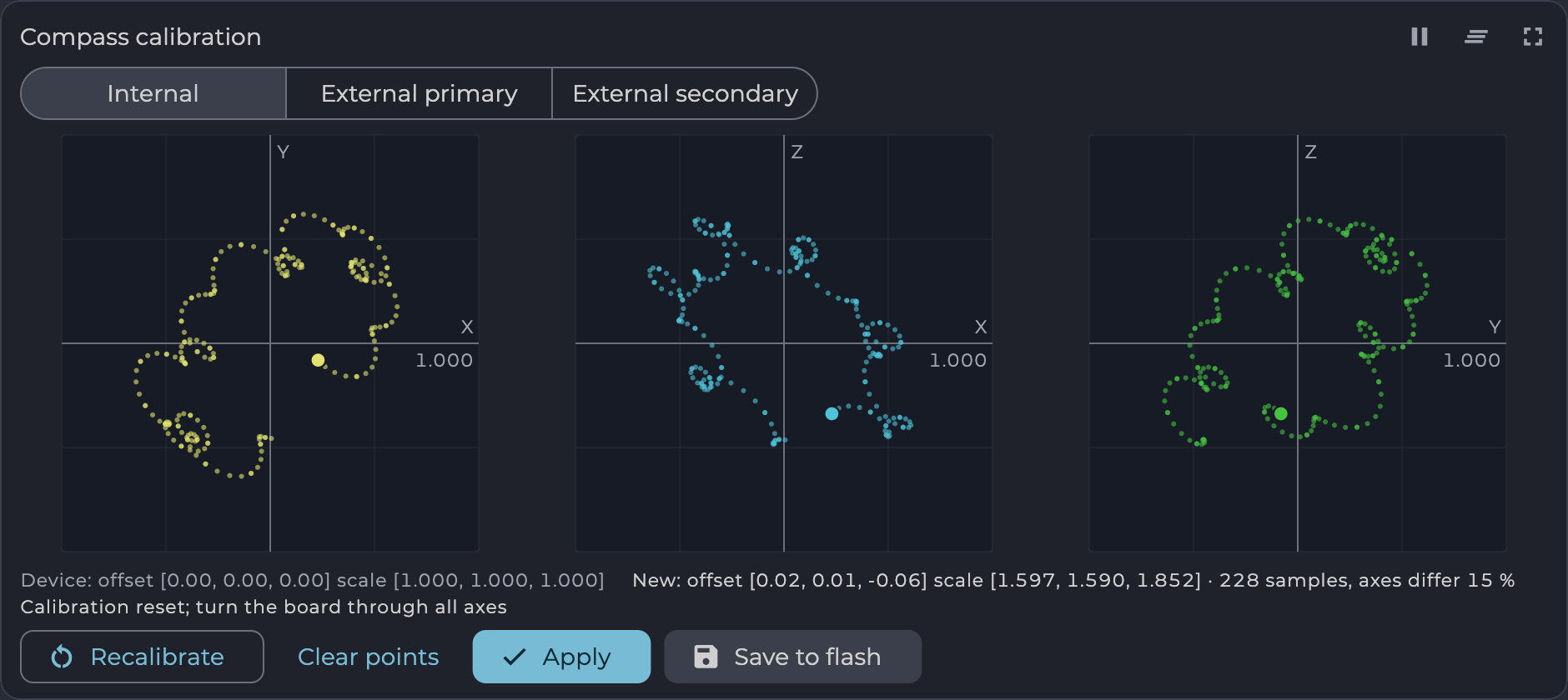
Figure: UTX Compass Calibration, Capturing Points After a Reset
Transmitter Dashboard
The transmitter’s dashboard tab displays its live data:
- Board: health of the sensors, memory and step-up converter.
- Emitters: LED currents, supply voltage (not valid when powered from USB) and temperature.
- LED channels: current of each emitter channel.
- IMU: transmitted attitude, heading by source, IMU data and compass calibration.
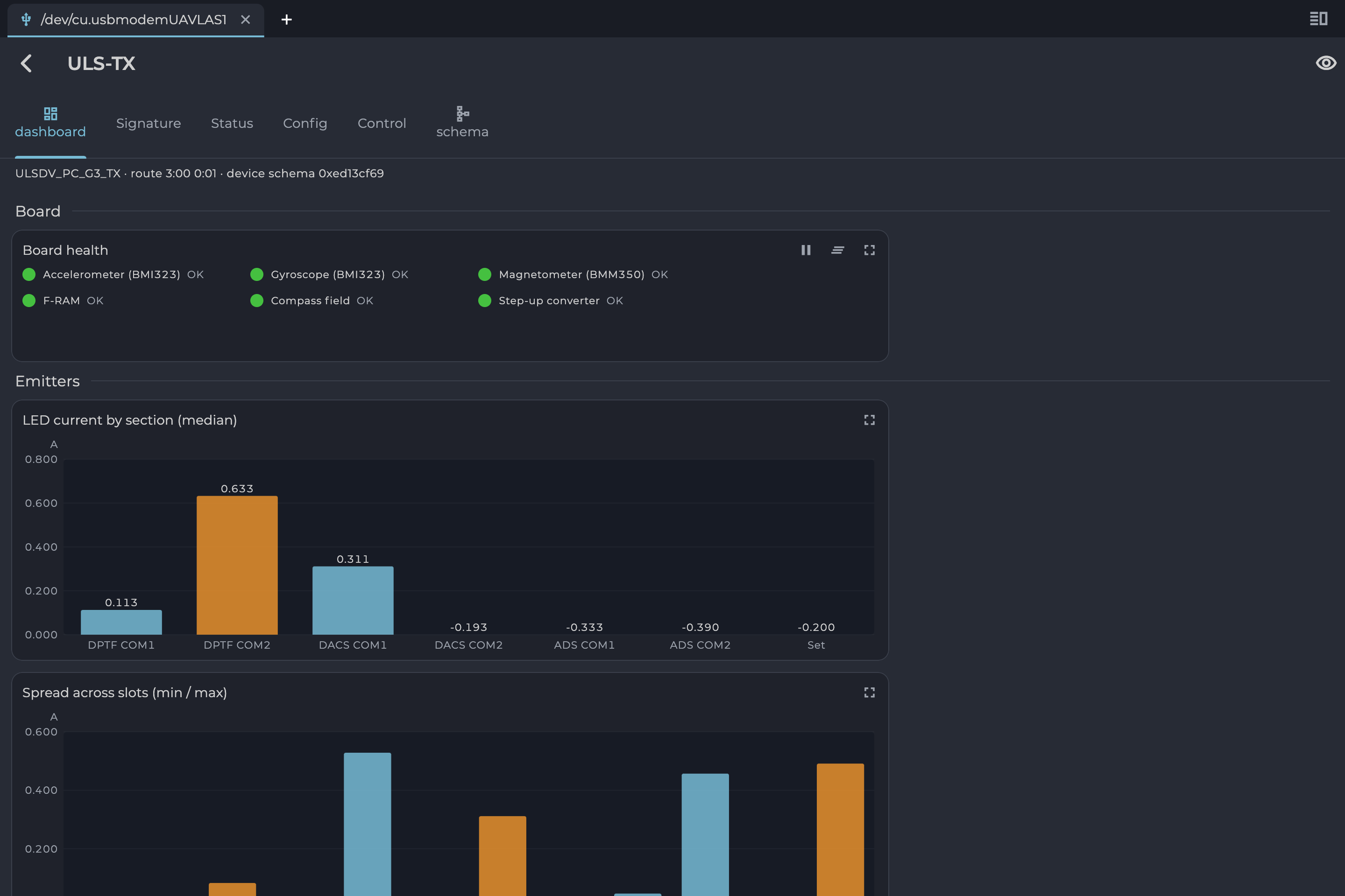
Figure: UTX Transmitter Dashboard
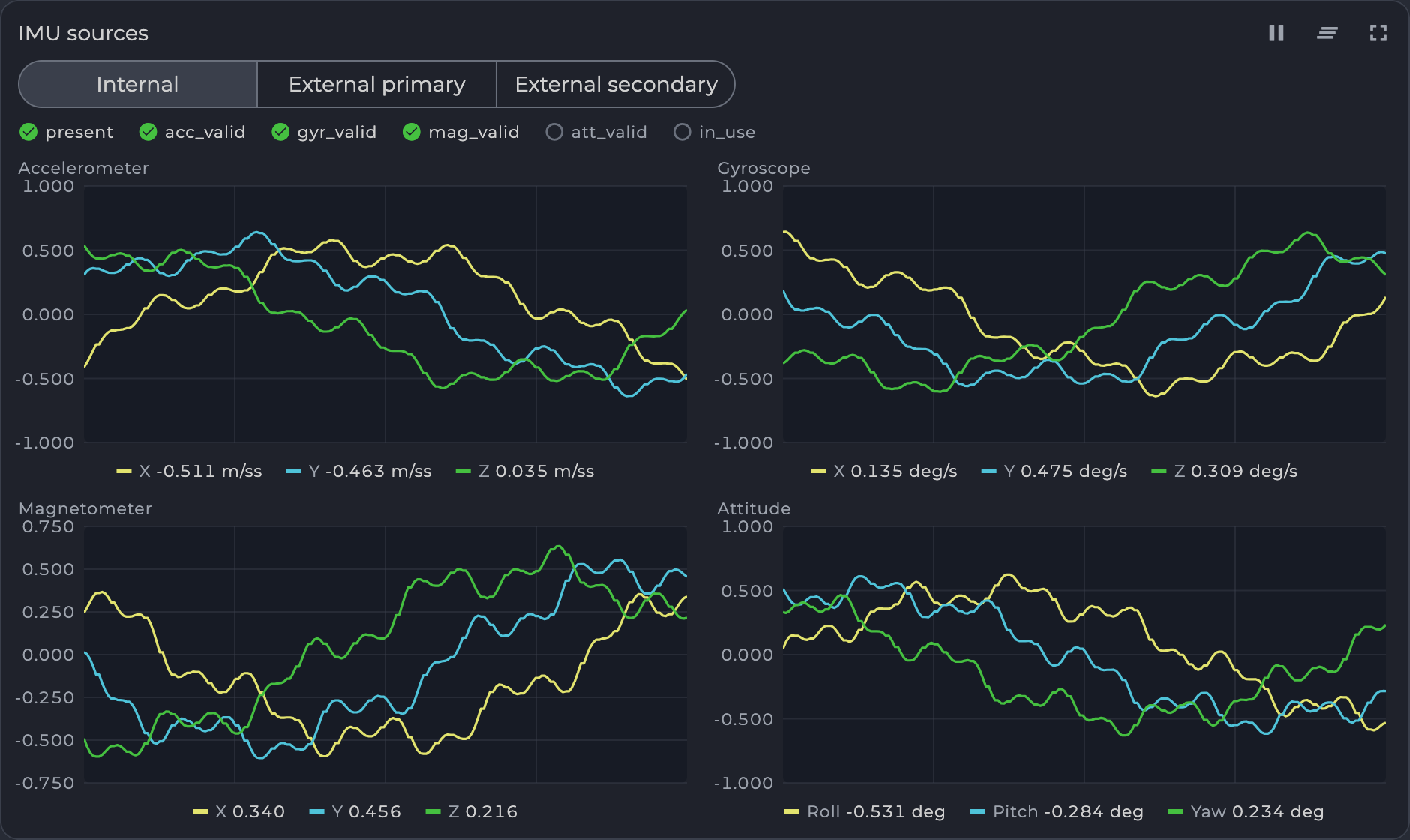
Figure: UTX IMU Charts
LED Indicator
You can check the status of the transmitter by looking at its LED indicator. The LED flashes in sequences of colors, so it can flash green-red-off-off or green-off-blue-off.
| Flash color | Description |
|---|---|
| Green | Normal operation. |
| Orange | Low voltage. |
| Red | Problem, check device. If it is first in sequence it can be led malfunctions of power voltage below minimum, second for compass fail detect. |
| Blue | Compass ok and device points to the North (brightness of illumination depends on how precise it is pointed to the North). |
Table: LED Indicator Status Colors
On-board Unit Installation (Receiver)
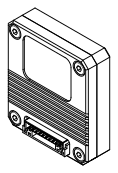
Figure: ULSDV-PC-G3-RX Receiver, Connector Side
The receiver can be installed both inside and outside the vehicle. However, please note that the receiver is not protected against moisture and dust. The orientation of the receiver does not matter; however, when installing the receiver, ensure line-of-sight conditions between the transmitter and receiver throughout the entire field of view of the receiver (100 deg).
Once the receiver is installed, enter the receiver offset and orientation information into the configuration.
Wiring Receiver to Autopilot over UART
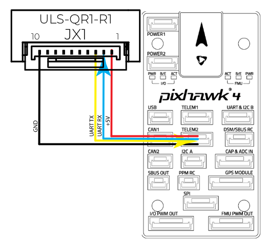
Figure: Receiver to Pixhawk 4 UART Wiring
Wiring for MultiRX Mode (MRX)
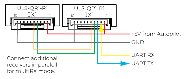
Figure: Receiver Wiring for MRX Mode
Configure Receiver in UTX
Open the receiver in the device list and select its Config tab.
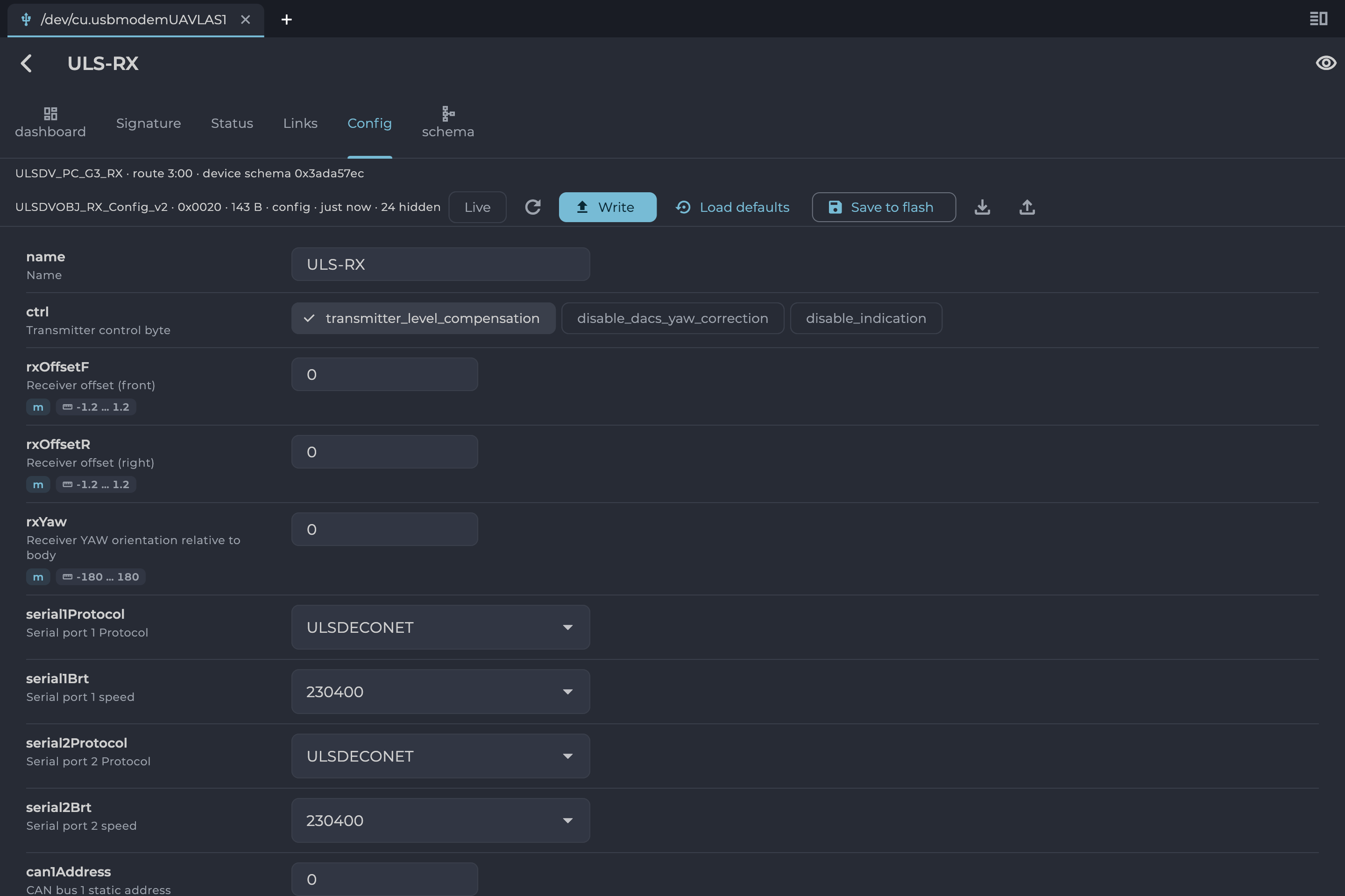
Figure: UTX Receiver Configuration
| Setting | Level | Description |
|---|---|---|
| name | Normal | Name of the device shown in the device list. |
| ctrl: transmitter_level_compensation | Normal | Compensates Pan-Tilt rotations of the transmitter. Used when landing on moving objects. |
| ctrl: disable_dacs_yaw_correction | Normal | Disables the Distance and Azimuth Correction System. When DACS is enabled, the receiver uses the transmitter DACS stage to correct its yaw orientation relative to the transmitter. |
| ctrl: disable_indication | Normal | Disables the receiver LED indicator. |
| rxOffsetF, rxOffsetR | Normal | Location of the receiver on the drone, front and right, in meters. Used to calculate the drone heading in MRX mode. |
| rxYaw | Normal | Receiver yaw installation orientation relative to the vehicle front. |
| serial1Protocol, serial2Protocol | Normal | Protocol used to communicate with the autopilot. |
| serial1Brt, serial2Brt | Normal | Speed of the serial port. |
| can1Address | Normal | Static address on the CAN bus. |
| can1Speed | Normal | Speed of the CAN bus. |
| mavlinkFrames | Normal | MAVLink V2 messages to send: MAV_FRAME_BODY_FRD (ArduPilot), MAV_FRAME_LOCAL_NED (PX4), MAV_FRAME_LOCAL_OFFSET_NED and VISION_POSITION_ESTIMATE. |
| indicatorBrightness | Normal | Brightness of the LED indicator, in %. |
Table: Receiver Configuration Settings, Normal Level
| Setting | Level | Description |
|---|---|---|
| rxGain | Advanced | Analog gain of the receiver front end, in dB. Lower it when the emitter is close enough to saturate the input stage, raise it for range. It does not re-scale the reported position. |
| rxAmplification | Advanced | Amplification of the measured signal for signal lost in front of the receiver, such as a cover glass, in dB. Raise it until the reported distance matches the true one. It adds no range. |
| relPosGain, relVelGain | Advanced | Gain of the relative position and velocity. |
| angScale | Advanced | Scale of the X and Y deviation angles from the transmitter’s centre line. Raise an axis when its offset reads short of the true one, lower it when it reads long. |
| predictionTime | Advanced | Time to predict positions when there is no signal, in seconds. It avoids the effect of short signal interruptions. Generally set from 0.3 s up to 1 s. |
| positionFilterAcc | Advanced | Acceleration of the position filter. |
Table: Receiver Configuration Settings, Advanced Level
Receiver Dashboard
The receiver’s dashboard tab displays its status. Check the Landing solution lamps to see what the receiver has calculated. For the lamp colors and the other widgets, see Widget Reference in the ULSToolsX User Manual.
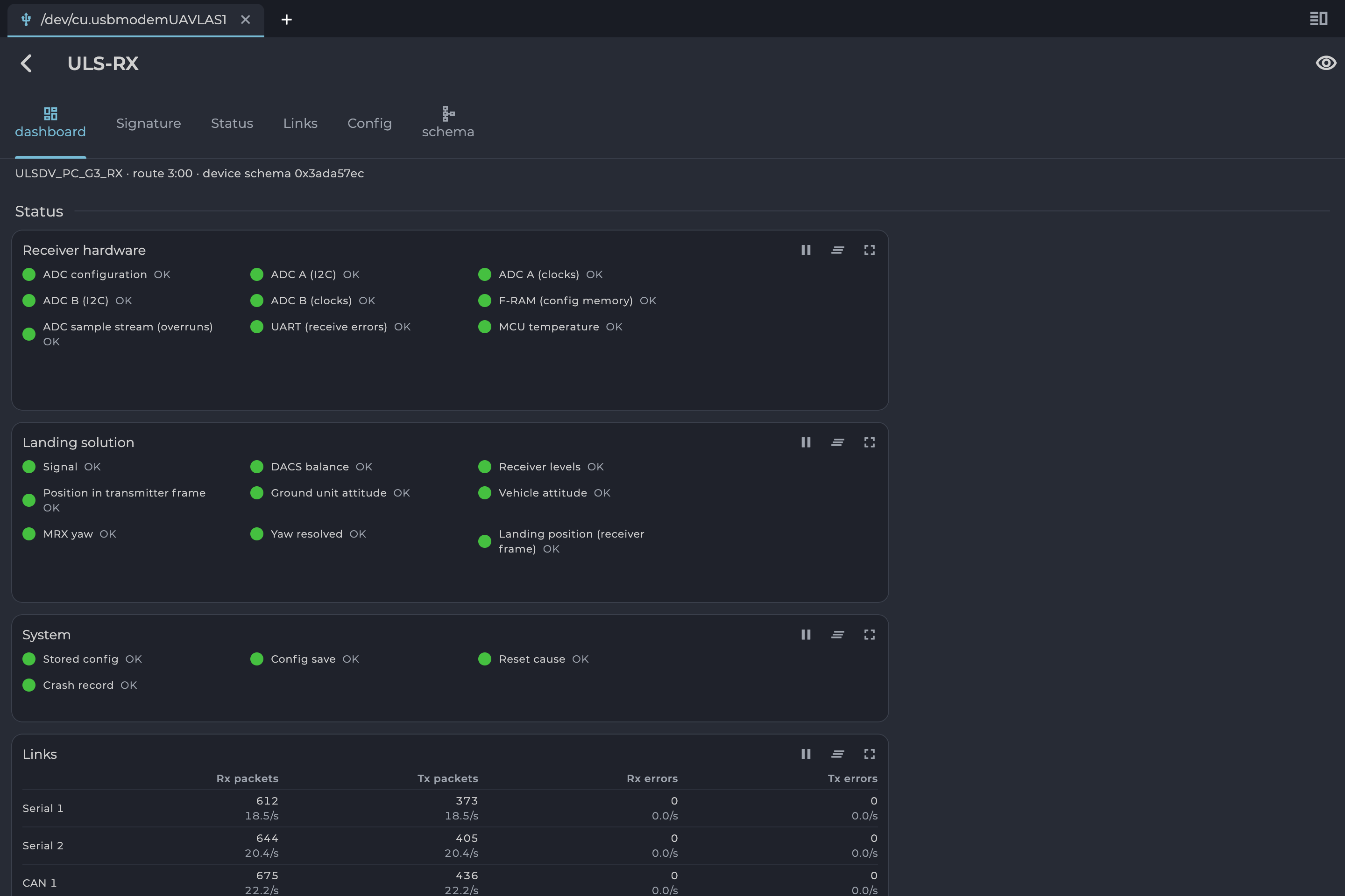
Figure: UTX Receiver Dashboard
| Lamp | Green means |
|---|---|
| Signal | The signal from the transmitter is received. |
| DACS balance | The DACS signal pairs are balanced. |
| Receiver levels | The receiver levels agree with each other. |
| Position in transmitter frame | The position relative to the transmitter is estimated. |
| Ground unit attitude | The ground unit orientation is received. |
| Vehicle attitude | The vehicle attitude is received from the autopilot. |
| MRX yaw | Yaw orientation is calculated using MRX. |
| Yaw resolved | The yaw orientation is available. |
| Landing position (receiver frame) | The landing position relative to the receiver is calculated. |
Table: Receiver Landing Solution Lamps
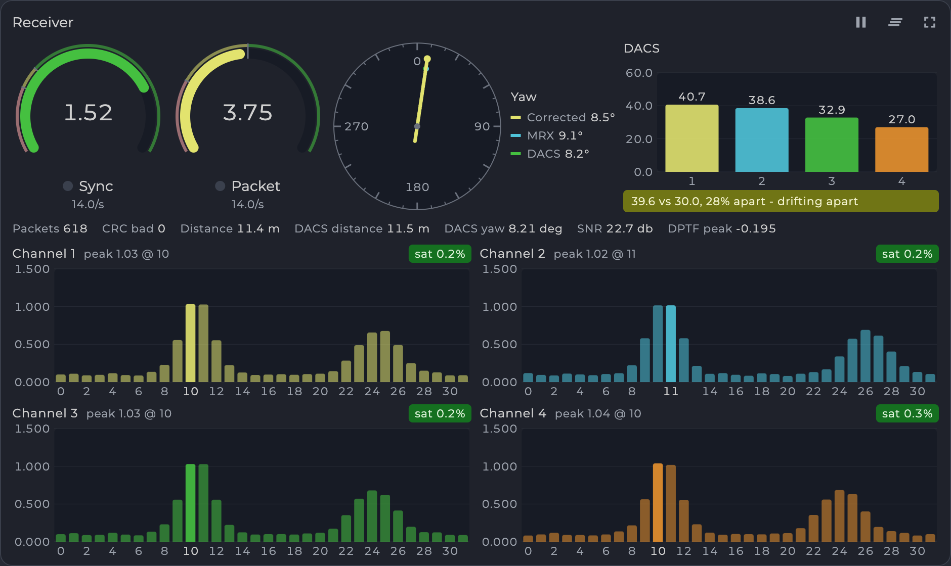
Figure: UTX Receiver Panel
Setup MRX Mode
This option uses data from two receivers to calculate position. It calculates the receiver yaw orientation using the triangular method. In this mode, compass data (on ground and on board) does not affect the position estimation, so it is a more robust way to land. In this mode the maximum distance is limited to 10 m; above that, the system uses compass mode. DACS, when enabled, supports the MRX yaw calculation.
To set up and check MRX mode:
- Connect the receivers on board with CAN bus.
- Configure rxOffsetF and rxOffsetR for both receivers.
- Configure rxYaw for both receivers.
- After setup, hover the drone above the transmitter (1 m - 2 m) and check on the Distance chart that the MRX and Distance lines are the same (+/- 20%).
- Correct rxOffsetF and rxOffsetR if the two lines are not approximately the same. Increasing the distance between receivers increases MRX, and vice versa.
- Rotate the drone over the transmitter (1 m - 2 m) and check the MRX line on the Yaw chart. It must correspond to the heading of the drone relative to the transmitter.
Receiver Charts
The receiver’s dashboard tab also displays charts, including:
- Positions in different coordinate systems
- Distance and yaw
- Vehicle information (position, velocity and attitude)
- Ground unit attitude
- Signal level, temperature and voltage
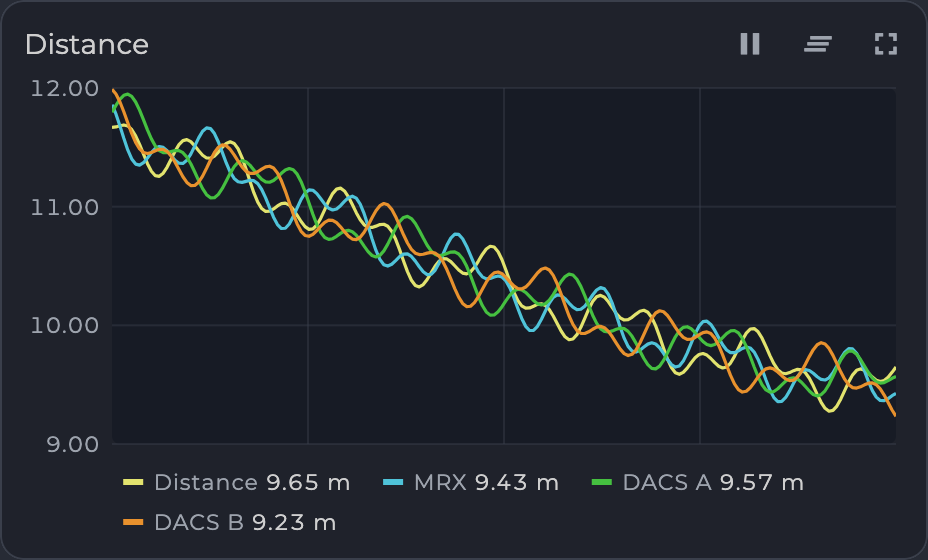
Figure: UTX Distance Chart
Integration Instructions for ArduPilot Based Systems
Preparing for Integration
- Use the latest version of ULSToolsX (UTX). Connect all UAVLAS devices to a PC and update their firmware before proceeding. See the ULSToolsX User Manual (ULSDC-PBUM021126).
- Update the autopilot to the latest ArduCopter version.
- Install the transmitter and receiver(s) and wire the receiver to a free autopilot UART (TELEM) port. Pinouts and wiring diagrams are in this manual and the Interface Control Document.
- Configure the transmitter in UTX.
- Configure the receiver in UTX (on dual-receiver systems, configure both receivers).
The system communicates with ArduPilot over MAVLink 2 and reports the target in MAV_FRAME_BODY_FRD.
Example of receiver configuration:
On the receiver’s Config tab, set the following for the serial port wired to the autopilot, then select Write and Save to flash. The example uses serial port 1.
| Setting | Value |
|---|---|
| serial1Protocol | MavlinkV2 |
| serial1Brt | 230400. Must match the autopilot port speed |
| mavlinkFrames | MAV_FRAME_BODY_FRD |
Table: Receiver Settings for ArduPilot
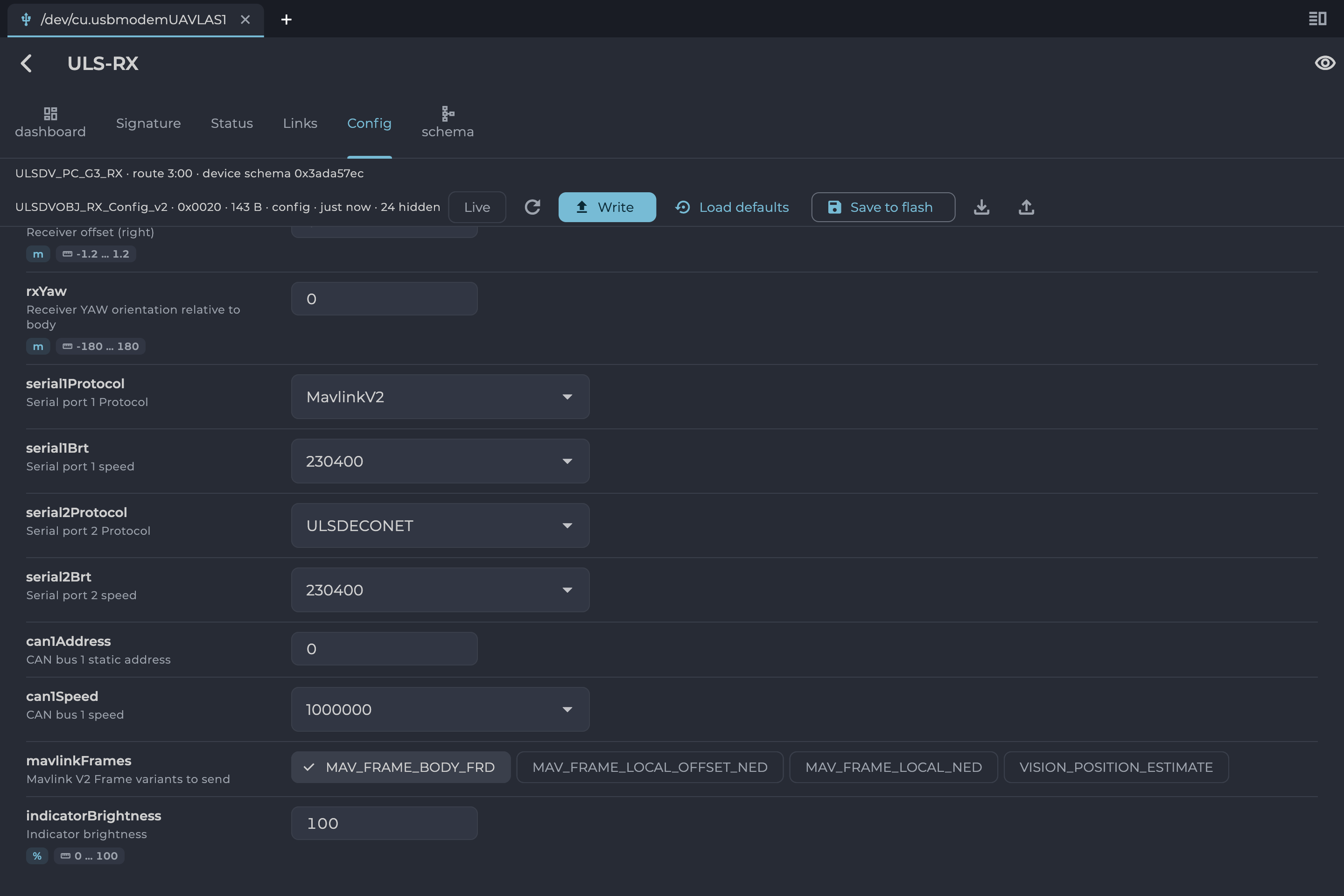
Figure: UTX Receiver Configuration for ArduPilot
Autopilot Configuration
Setup PLND Section
| Param | Value | Comment |
|---|---|---|
| PLND_ENABLED | 1 | Enable the precision landing module |
| PLND_TYPE | 1 | Use type = 1 to enable UAVLAS sensor over the companion computer driver |
Table: ArduPilot PLND Section Parameters All other PLND parameters should remain at defaults, or be set according to your vehicle requirements.
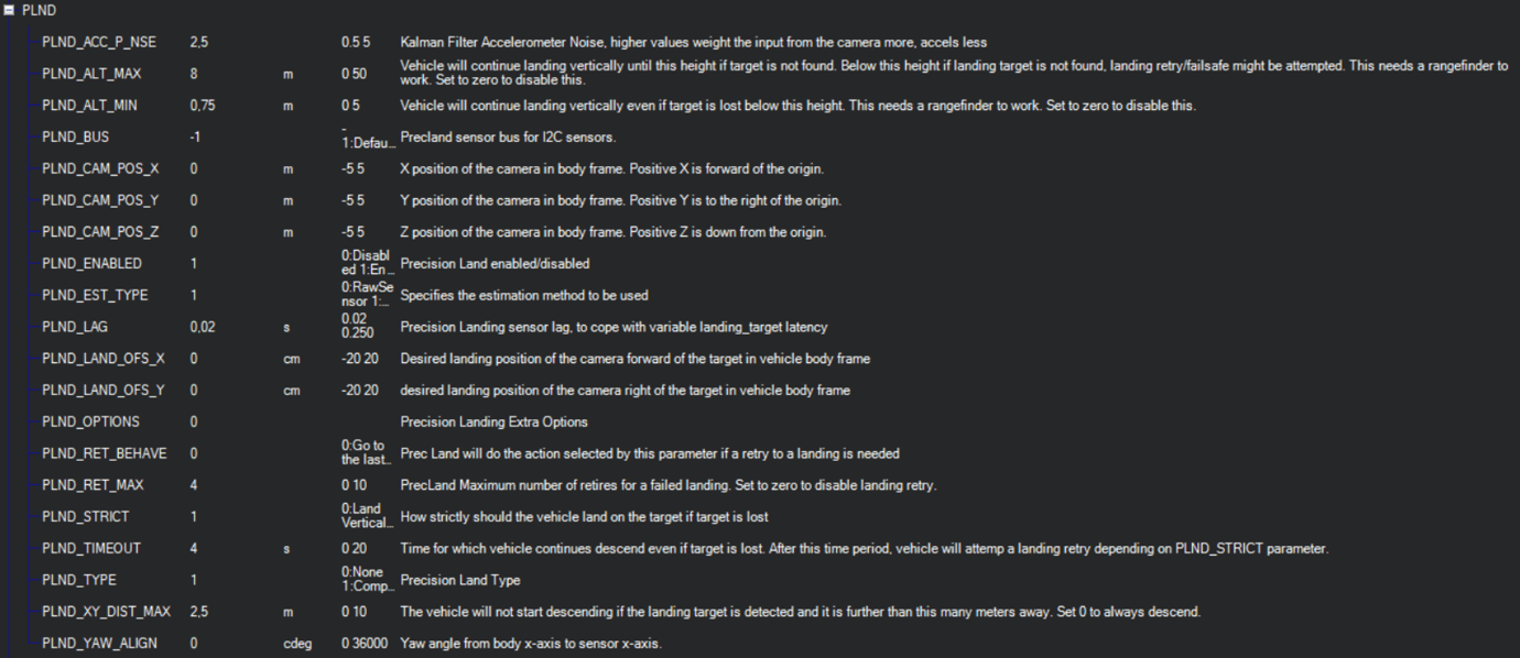
Figure: PLND Configuration Example
Set Up Serial Communication in SERIALx Section
The example uses SERIAL2; use the number of the port the receiver is wired to.
| Param | Value | Comment |
|---|---|---|
| SERIAL2_BAUD | 230 | Baud rate — must match the receiver UART baud rate setting |
| SERIAL2_OPTIONS | 0 | Default |
| SERIAL2_PROTOCOL | 2 | MAVLink 2 protocol |
Table: ArduPilot SERIALx Section Parameters Set up serial stream rates in the SRx section. The sensor requires the following data from the autopilot:
| Param | Value | Comment |
|---|---|---|
| SR2_EXTRA1 (or MAV2_EXTRA1) | 20 | Attitude stream at 20 Hz — required for compass mode yaw orientation |
| SR2_POSITION (or MAV2_POSITION) | 20 | Optional — Vehicle LOCAL_POSITION_NED stream at 20 Hz for absolute target position calculation |
Table: ArduPilot SRx Stream Rate Parameters
Check Setup
When configuration and wiring are correct, GPS is available, and the receiver is in the field of view of the transmitter, you will see the LANDING_TARGET MAVLink message in the MAVLink Inspector (Mission Planner example shown):
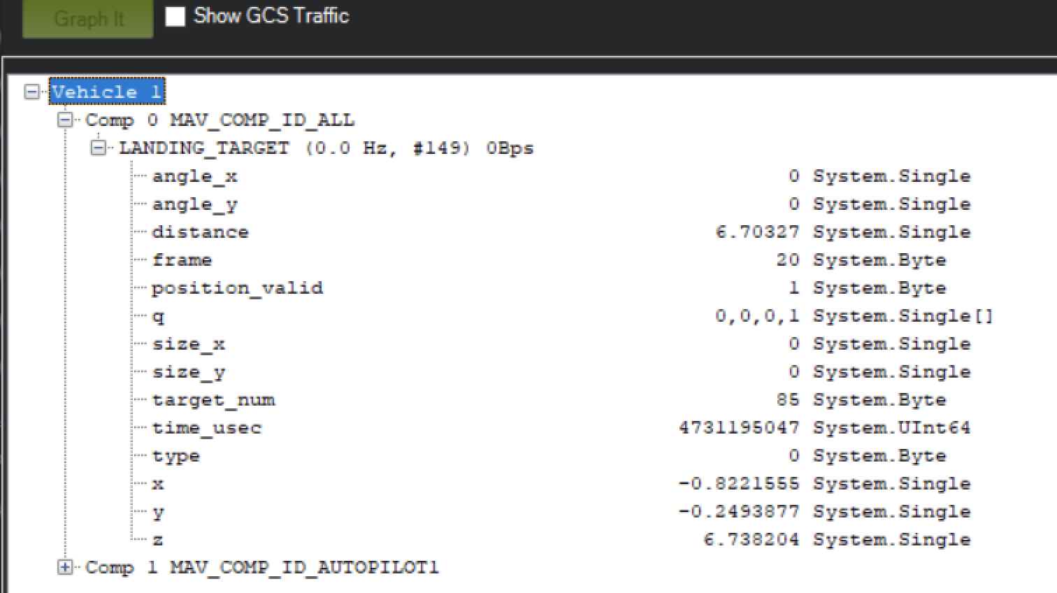
Figure: LANDING_TARGET Message in MAVLink Inspector
Setup Precision Loiter Mode
Attach any unused switch to the PrecLoiter option to enable precision loiter mode:
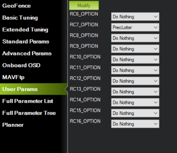
Figure: PrecLoiter Switch Configuration
Activate the switch and confirm messages “PrecLoiter: LOW” and “PrecLoiter: HIGH” appear. After a test flight above the target, check telemetry for PL offset data.
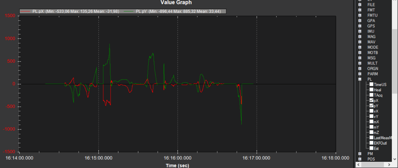
Figure: Telemetry Data Showing PL Offsets
PID Tuning
In case of oscillations or instability during landing, check the PID parameters in ArduPilot Extended Tuning.
It is recommended to tune Position XY, Velocity XY, and Loiter Speed for the best performance:
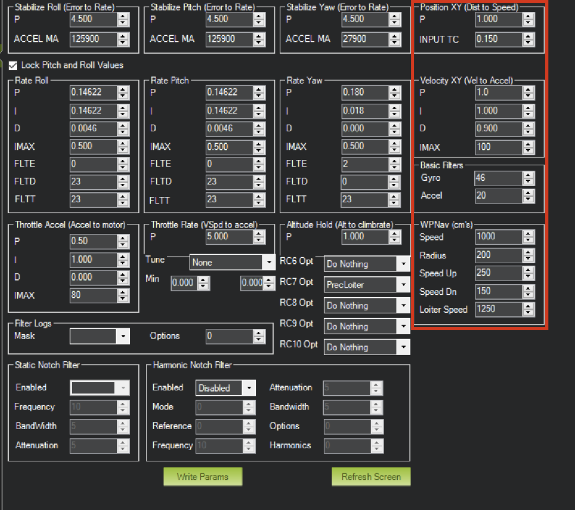
Figure: ArduPilot Extended Tuning Parameters
For additional information, see the ArduPilot documentation at https://ardupilot.org/ardupilot/
Integration Instructions for PX4 Based Systems
Preparing for Integration
- Use the latest version of ULSToolsX (UTX). Connect all UAVLAS devices to a PC and update their firmware before proceeding. See the ULSToolsX User Manual (ULSDC-PBUM021126).
- Update the autopilot to the latest PX4 version. The stock PX4 firmware supports UAVLAS systems; no custom build is needed.
- Install the transmitter and receiver(s) and wire the receiver to a free autopilot UART (TELEM) port. Pinouts and wiring diagrams are in this manual and the Interface Control Document.
- Configure the transmitter in UTX.
- Configure the receiver in UTX (on dual-receiver systems, configure both receivers).
The system communicates with PX4 over MAVLink 2 and reports the target in MAV_FRAME_LOCAL_NED.
Example of receiver configuration:
On the receiver’s Config tab, set the following for the serial port wired to the autopilot, then select Write and Save to flash. The example uses serial port 1.
| Setting | Value |
|---|---|
| serial1Protocol | MavlinkV2 |
| serial1Brt | 460800. Must match the autopilot port speed |
| mavlinkFrames | MAV_FRAME_LOCAL_NED |
Table: Receiver Settings for PX4
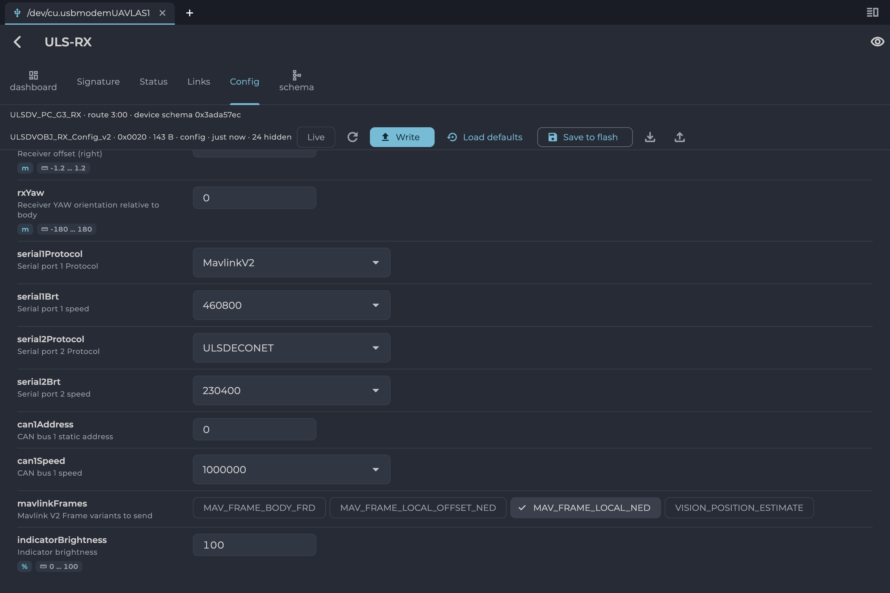
Figure: UTX Receiver Configuration for PX4
Configure PX4 Autopilot
Values are provided as an example (Pixhawk4-mini AP):
| PX4 Parameter | Value | Comment |
|---|---|---|
| MAV_1_CONFIG | TELEM/SERIAL4 | Requires reboot to apply the next parameters |
| MAV_1_FORWARD | Enabled | Forward MAVLink messages |
| MAV_1_MODE | Onboard | Set link mode to onboard |
| SER_TEL4_BAUD | 460800_8N1 | Must match the UART baud rate set in the receiver configuration |
Table: PX4 Autopilot Configuration Parameters
Running and Testing
After configuration and wiring, power up the drone and transmitter. In QGroundControl, go to Analyze Tools → MAVLink Inspector and check for the LANDING_TARGET MAVLink message.
If the vehicle is providing a LOCAL_POSITION_NED message to the UAVLAS system and is hovering over the beacon, the field position_valid = 1 will appear in LANDING_TARGET.
To perform precision landing, create a flight plan and enable the Precision Landing option on the landing waypoint.
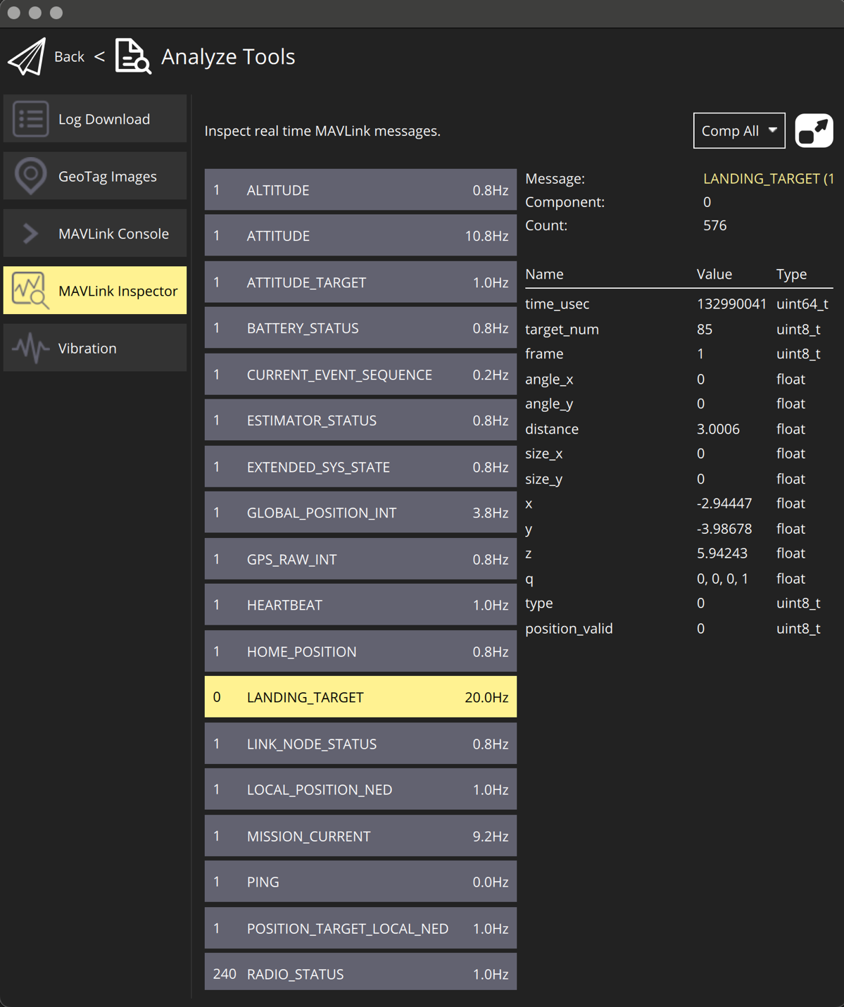
Figure: LANDING_TARGET Message in QGroundControl
For additional information, see the PX4 documentation at https://docs.px4.io/main/en/
Troubleshooting
Before You Start
Most problems are solved by bringing everything up to date and repeating the setup:
- Use the latest version of ULS-Tools.
- Update the firmware of the transmitter and all receivers.
- Use the latest ArduPilot or PX4 firmware.
- Check the receiver and transmitter LED indications against the Operation Manual of your product.
No MAVLink Message (No Position Data)
Symptom: the autopilot receives no LANDING_TARGET message from the receiver.
- Check that the transmitter is switched on and the receiver is in its field of view, with a clear line of sight.
- Check the receiver power and the wiring of power, RX and TX (see the pinout and wiring diagram in the product’s Interface Control Document).
- Check that the serial port baud rate and protocol on the autopilot match the receiver configuration (MAVLink 2).
- On ArduPilot, check that the EXTRA1 (attitude) stream is enabled for the receiver’s serial port.
- Check the receiver frame configuration: MAV_FRAME_BODY_FRD for ArduPilot, MAV_FRAME_LOCAL_NED for PX4.
- Check the transmitter power supply.
- When testing with QGroundControl, connect over telemetry, not USB: LANDING_TARGET may not be shown over a USB connection.
Intermittent Position Data
Symptom: position data drops in and out.
- Keep the approach corridor and the line of sight between transmitter and receiver clear.
- Re-orient the receiver(s) or the transmitter so the receiver stays inside the transmitter’s field of view.
- Reduce the operating distance if you are close to the product’s maximum range.
- Clean the receiver lens and the transmitter emission window.
- Secure the receiver mounting to reduce vibration.
Inaccurate Position or Offset
Symptom: the reported position shows a large or constant offset from the real one.
- Check that the receiver is mounted in the correct orientation and the mounting offset is set in the receiver configuration.
- Check that the transmitter is level and its compass/IMU is calibrated.
- Check for magnetic interference near the transmitter.
- Indoors, reflections can disturb the measurement; test outdoors or in a controlled environment.
Not Holding in Precision Loiter Mode but MAVLink Message OK
- Check that precision loiter is set up on the autopilot (a switch assigned to PrecLoiter on ArduPilot), and that PLND_ENABLED and PLND_TYPE are set.
Circular Motions During Landing
- Check the compass calibration of the ground unit (transmitter).
- Check the compass calibration of the autopilot.
- Check for magnetic interference on the ground.
- Use compass override mode to debug the landing.
- Check the precision landing PID settings.
The Landing Is Not Precise Enough
- Check the position control PID settings of the autopilot.
- On ArduPilot, check the Kalman filter settings of the PLND section.
- Check the filter smoothness parameter on the receiver.
- Check the trajectory jerk settings on the autopilot.
Transmitter or Receiver Not Powering
- Check that the supply voltage is within the range given in the product’s datasheet.
- Check the cables, connectors and the aircraft power rail.
If Nothing Works
Update the firmware of all UAVLAS devices, reset them to default settings and repeat the setup. Update the autopilot firmware, reset the autopilot parameters to default, and perform the autopilot calibrations and settings from the beginning. If the problem persists, contact UAVLAS support at https://uavlas.com/contact/ with your product, firmware versions and a flight log.
Change Control
All changes to this document must be reviewed and approved by the relevant technical leads and stakeholders
References
- ULSDC-PBDS271026-ULS-ProCopter-G3-Datasheet
- ULSDC-PBICD271026-ULS-ProCopter-G3-ICD