ULS-XCopter-G2 Interface Control Document
ULSDC-PBICD310325 · version 0.1.0 · issued April 2, 2025
The numbered PDF is the controlled copy: download it from the portal.
Introduction
Purpose
This document outlines the interfaces between the ULS-XCopter-G2 system components, including the transmitter, receiver, and autopilot systems (Ardupilot and PX4 and similar).
Scope
This document is intended for use by system engineers, integrators, and developers working with ULS-XCopter-G2 systems. It provides detailed information on the interfaces between the system components, ensuring seamless integration and operation.
System Components
Transmitter (Ground Unit)
A transmitter is a device placed on the ground (platform, moving object). It emits a signal in the Infrared range and serves as a kind of beacon. Transmitter marks position for drone landing.
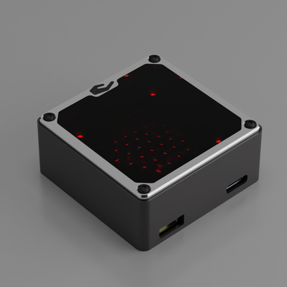
The primary function of the transmitter is to continuously send out a coded signal that can be detected and interpreted by the receiver unit onboard the XCopter. This signal contains critical information needed for the operation of the ULS-XCopter, such as positional data, commands, and system status.
Receiver (Onboard Unit)
A receiver is a device that is placed on board an aircraft.
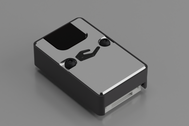
The receiver decodes this signal to derive flight information such as positional coordinates, real-time transmitter status updates, and landing guidance. It interprets the data to navigate accurately and ensure drone follows the intended flight path. It provides feedback to the autopilot systems, such as Ardupilot and PX4, to adjust the flight parameters as needed for optimal and safety landing or hovering above.
Interface Overview
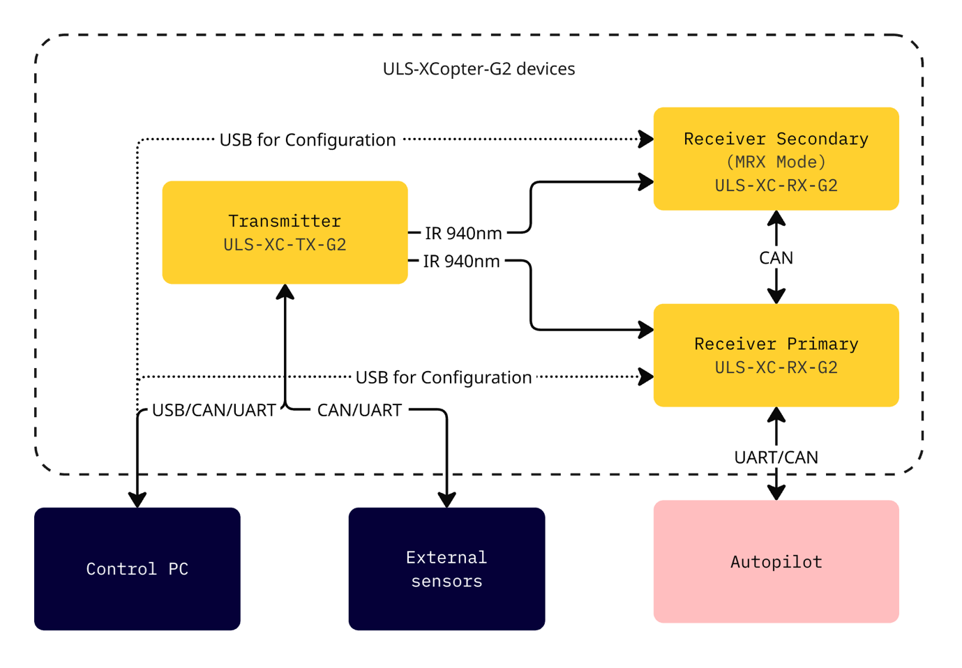
Figure: ULS-XCopter-G2 Interface Overview
Transmitter to Control PC Interface
Data Type:
- Status information
- Control signals
- Transmitter configuration
Connection Type:
- CAN
- USB
- UART
Transmitter to External Sensors Interface
Data Type:
- Control signals
- External IMU/COMPASS data
Connection Type:
- CAN
- UART
Transmitter to Receiver Interface
The transmitter and receiver use an optical interface to exchange data. Transmission uses IR emission at 940 nanometers. Data transmission is only in the direction from the transmitter to the receiver.
Data Type:
- Position encoded data
- Status encoded data (Transmitter orientation and instructions)
Connection Type:
- Optical IR 940nm (Infrared optical link)
Data Flow:
Data is transmitted unidirectional from the transmitter (ground unit) to the receiver (onboard unit) via infrared optical signals. The receiver decodes the optical signals to extract:
- Positional field information
- Ground unit IMU data
- System status and commands
Transmitter Pinout
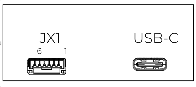
Figure: ULS-XCopter-G2 Transmitter Main Connector
| Pin Number | XCopter-G1&G2 |
|---|---|
| 1 | Vcc Input (+7.5V..+27V) |
| 2 | CAN2 H |
| 3 | CAN2 L |
| 4 | UART TX |
| 5 | UART RX |
| 6 | GND |
Table: Transmitter Main Connector Pinout (JX1)
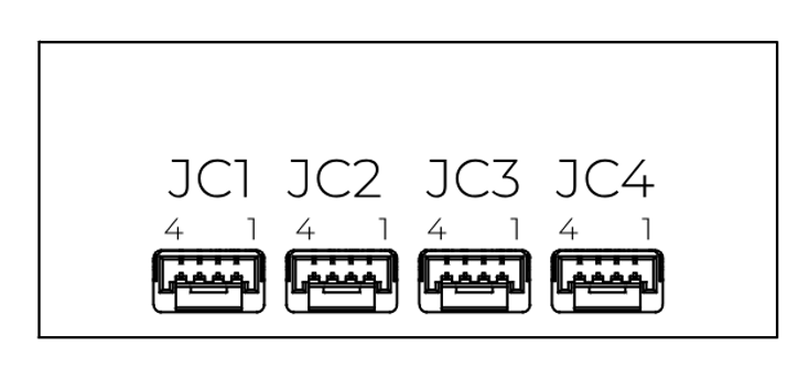
Figure: ULS-XCopter-G2 Transmitter Submodule Connectors
| Pin Number | XCopter-G1&G2 |
|---|---|
| 1 | +5V Output |
| 2 | CAN1 H |
| 3 | CAN1 L |
| 4 | GND |
Table: Transmitter Submodule Connectors Pinout (JC1-JC4)
Receiver to Autopilot and PC Interfaces
Data Type:
- Mavlink messages
- ULS-Blitz frames
- ASCII protocol
Connection Type:
- UART
- CAN
- USB
Data Exchange:
- Control PC is used to configure and view status of the receiver
- Autopilot Communication: Receiver accepts NED (North-East-Down) and attitude information from autopilot to convert coordinate systems
- Position Data: Receiver sends position offset data to autopilot
- Multi-Receiver Communication: Several receivers can communicate to calculate vehicle orientation (YAW)
receiver Pinout
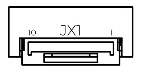
Figure: ULS-XCopter-G2 Receiver Connector
| Pin Number | XCopter-G2 |
|---|---|
| 1 | +5V Input |
| 2 | UART RX |
| 3 | UART TX |
| 4 | CAN H |
| 5 | CAN L |
| 6 | USB D- |
| 7 | USB D+ |
| 8 | UART2 RX |
| 9 | UART2 TX |
| 10 | GND |
Table: Receiver Pinout (JX1)
Powering Interfaces
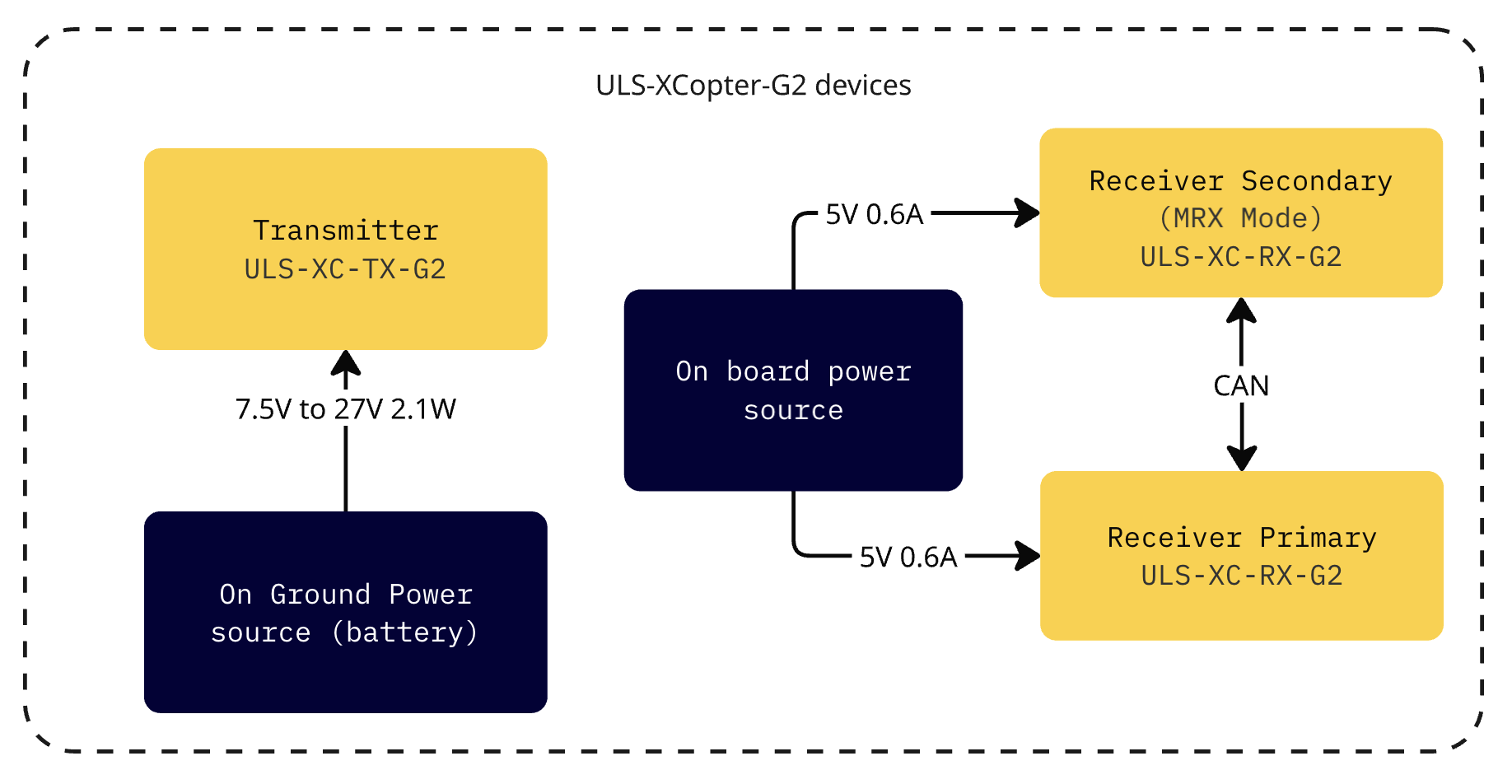
Figure: ULS-XCopter-G2 Powering Interfaces
| Parameter | Value | Unit |
|---|---|---|
| Supply Voltage | 7.5 - 27 | V |
| Supply Current | 2.0 | A |
| Power Consumption | 2.1 | W |
Table: Transmitter Electrical Characteristics
| Parameter | Value | Unit |
|---|---|---|
| Supply Voltage | 5.0 | V |
| Supply Current | 0.6 | A |
| Power Consumption | 0.3 | W |
Table: Receiver Electrical Characteristics
Functional Interfaces
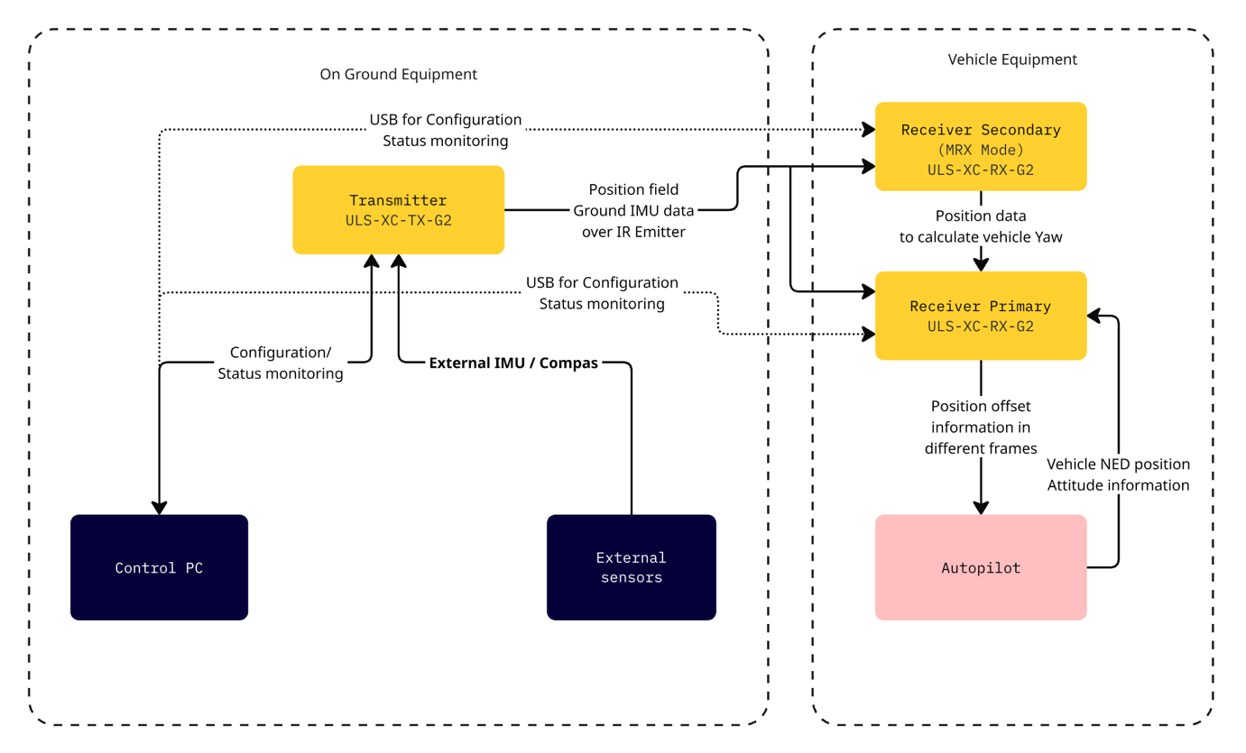
Figure: ULS-XCopter-G2 Functional Interfaces
Data Exchange
- Control PC used to configure and view status of transmitter.
- Control PC used to set configuration of receivers.
- Control PC (or embedded equipment instead control pc) can be used to send control signals (On/off, compass override information)
- External IMU/Compass equipment can be used to override internal IMU/compass information.
- Receiver accept data from transmitter over IR signal. This data include position field information and ground unit IMU data.
- Receiver accept NED and Attitude information from autopilot to be able convert coordinate system that can be accepted by autopilot.
- Several Receivers can communicate to be able calculate vehicle orientation YAW.
- Receiver send position offset data to autopilot.
Mechanical Interfaces
Transmitter Mechanical Interface
Figure: Transmitter Mechanical Interface
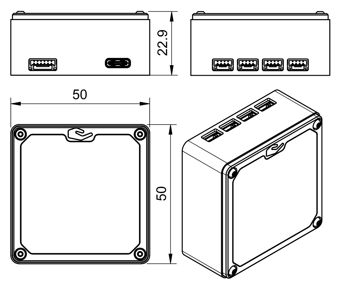
Figure: Transmitter dimensions
Receiver Mechanical Interface
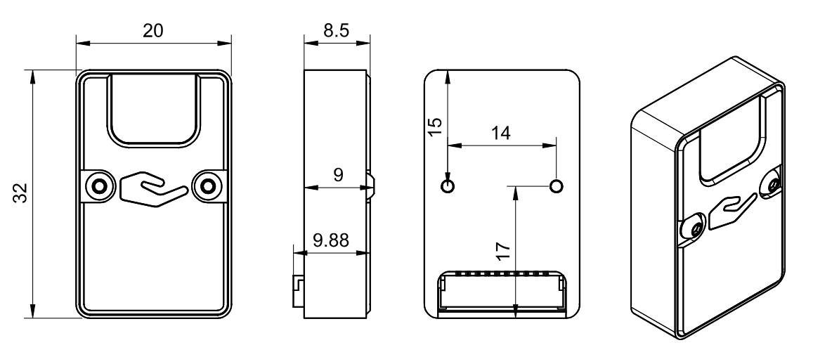
Figure: Receiver Mechanical Interface
Environmental Conditions
The system is designed for commercial-grade environmental operation, suitable for outdoor and industrial applications where robust performance under varying environmental conditions is required.
Operating Temperature
The system components are rated for extended temperature operation:
- Normal Operation: -20°C to +45°C when mounted on vehicle PCB
The wide operating temperature range enables deployment in diverse climates, from cold weather operations to hot desert environments.
Environmental Protection
- IP Protection Rating: IP54 (dust protected, splash water resistant)
- Note: While the system offers protection against dust ingress and water splashing, it is not waterproof. Additional protective measures may be required for operation in harsh weather conditions or marine environments.
Storage and Handling
- Storage Temperature: -40°C to +85°C
- Humidity: Up to 95% non-condensing
- Altitude: Operation up to 4000m above sea level
Environmental Considerations
Dust Protection: The IP54 rating provides protection against dust ingress that could interfere with system operation. Regular cleaning is recommended in particularly dusty environments.
Moisture Resistance: Protected against water splashing from any direction. However, avoid direct water jets, submersion, or prolonged exposure to heavy rain without additional protective enclosures.
Thermal Management: Ensure adequate ventilation around system components during operation. Avoid mounting in locations exposed to direct sunlight or near heat sources that could cause components to exceed maximum operating temperature.
Condensation: When moving equipment between environments with significant temperature differences, allow sufficient time for thermal equalization to prevent internal condensation.
| Parameter | Minimum | Maximum | Unit | Notes |
|---|---|---|---|---|
| Operating Temperature | -25 | +45 | °C | Normal operation |
| Storage Temperature | -40 | 85 | °C | Non-operating |
| Humidity | 5 | 95 | % | Non-condensing |
| IP Protection Rating | IP54 | Dust and splash resistant | ||
| Altitude | 0 | 4000 | m | Above sea level |
Table: Environmental Specifications - Commercial Grade
Change Control
All changes to this document must be reviewed and approved by the relevant technical leads and stakeholders.