ULS-XSpot-G3 Operation Manual
ULSDC-PBOM190426 · version 0.1.5 · issued August 9, 2026
The numbered PDF is the controlled copy: download it from the portal.
Introduction
Purpose
This manual provides installation, configuration, operation, verification, and troubleshooting guidance for the ULS-XSpot-G3 system.
Scope
This manual covers one tether-compatible transmitter and 2 identical, equal-priority RXM receivers used in the ULS-XSpot-G3 architecture.
Intended Audience
This manual is intended for operators, installers, technicians, and integrators responsible for commissioning and using the system.
Safety Information
- WARNING: The transmitter emits invisible infrared radiation when powered. Do not look into the emitter apertures at close range. See the Optical Radiation Safety section below.
- CAUTION: Route the tether cable through the transmitter centre through hole. Do not route the cable across the optical emission apertures.
- CAUTION: Do not connect or disconnect the transmitter interface under power.
Optical Radiation Safety (IR Emission)
The transmitter (ground unit) emits pulsed infrared optical radiation with a centre wavelength of 940nm. The receivers are optical sensors only and do not emit optical radiation.
Why This Warning Is Given
Radiation at 940nm is outside the visible range. The protective mechanisms that limit exposure to bright visible sources — the blink reflex, pupil constriction, and the instinct to look away — are not triggered by an invisible source. Exposure time is therefore limited only by operator behaviour, which is why the precautions below are given as operating instructions and not left to the operator’s judgement.
The transmitter is a positioning beacon. It is not an illumination product and is not intended to be viewed at any time.
Operating Precautions
- Do not look directly into the transmitter emitter apertures from a distance of less than 1 metre while the unit is powered.
- Treat the transmitter as emitting whenever supply voltage is applied, including when no receiver is present and no positioning data is being transferred.
- Switch emission off before working directly in front of the transmitter. Use the Illumination parameter in ULS-Tools to disable emission, or disconnect supply power.
- Do not view the powered transmitter through binoculars, telescopes, camera lenses, magnifiers, or any other light-collecting instrument. Such optics concentrate the emission and can raise the exposure at the eye by orders of magnitude compared with unaided viewing.
- Do not add, remove, or modify optical elements of the transmitter. Added optics change the emission characteristics and invalidate any photobiological classification of the unit.
- Position the transmitter so that the emission field is directed away from work positions and walkways where personnel stay for extended periods.
- Servicing personnel working inside the emission field at close range should disable emission first rather than rely on viewing distance.
Classification and Applicable Standards
| Item | Value |
|---|---|
| Emitter type | Incoherent IR LED array (not a laser) |
| Centre wavelength | 940nm |
| Emission mode | Pulsed |
| Applicable standard | IEC 62471 / EN 62471, Photobiological safety of lamps and lamp systems |
| Classification distance | 200mm (non-GLS source, per IEC 62471) |
| Risk group | TBD — to be entered from the IEC 62471 assessment report |
| Hazard distance | TBD — to be entered from the IEC 62471 assessment report |
Table: Optical Radiation Safety Data
For a 940nm source the applicable exposure limits are the retinal thermal hazard (380nm to 1400nm), the retinal thermal hazard for a weak visual stimulus (780nm to 1400nm, which applies specifically to sources that give no visual cue), and the infrared hazard to the cornea and lens (780nm to 3000nm). The corneal and lens limits are intended for chronic exposures longer than 1000s at a daily averaged irradiance of 100 W/m² or more.
Organisations operating this equipment within the European Union are additionally subject to Directive 2006/25/EC on the exposure of workers to artificial optical radiation, which requires the employer to assess worker exposure against the exposure limit values given in Annex I of that directive. UAVLAS provides the emission data needed for that assessment on request.
System Overview
ULS-XSpot-G3 is a tethered drone precision optical positioning system built around a tether-compatible ground transmitter (ULSDV-XS-G3-TX) and 2 equal-priority RXM onboard receivers (ULSDV-HLXS-G3-RXM). The system supports redundant onboard sensing and MRX-based yaw estimation for tethered flight and landing support.
ULS-XSpot-G3 uses the same HL/XS G3 platform as ULS-Heli-G3. Installation, configuration, and operating procedures are identical, except for the tether routing through the transmitter centre through hole (47mm x 47mm).
Package Contents
- 1x ULSDV-XS-G3-TX ground transmitter unit
- 2x ULSDV-HLXS-G3-RXM receiver units (Set A and Set B)
- 1x ULS-XX-USB-RS422 adapter (ground configuration)
- 2x ULS-XX-UART-RS422 onboard adapters (receiver-to-autopilot UART interface)
- Cables and mounting hardware
- Documentation package (may supply in online form)
System Requirements
- Transmitter power: +18V…+26V, 2.5A
- RXM receiver power (each): +12V…+26V, 1A
- Supported autopilots: Ardupilot and PX4 based systems (MAVLink V2), or any host supporting RS422/CAN/UART ULS protocols
Installation
Wiring Schematics

Figure: HL/XS G3 Ground-Side Wiring Schematic

Figure: HL/XS G3 Onboard Wiring Schematic
Transmitter Installation
The ULSDV-XS-G3-TX transmitter is a tether-compatible ground unit with a centre through hole for tether cable passage.
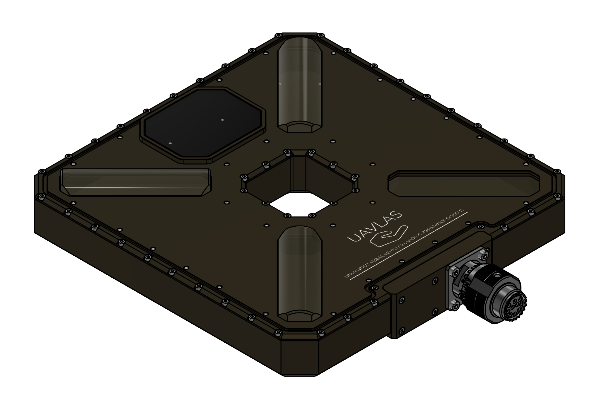
Figure: ULSDV-XS-G3-TX Transmitter
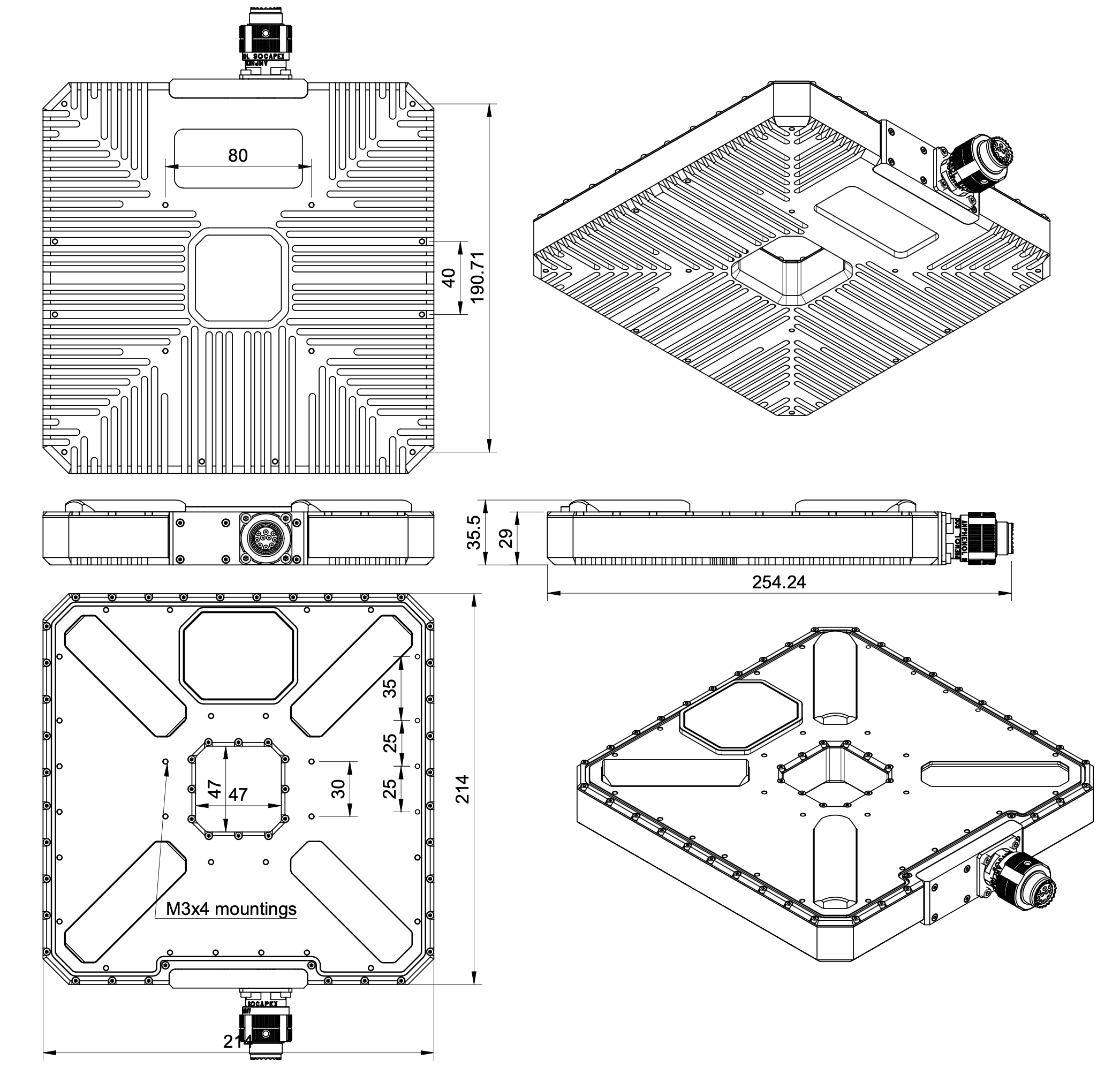
Figure: ULSDV-XS-G3-TX Dimensions
- Mounting instructions: device can be mounted from top side or from bottom side. Use corresponding M3 screws to mount device on place. 3D model and pad example can be provided by UAVLAS under request.
- Orientation requirements: The device must be positioned with the optical elements facing upward. Make sure that no foreign objects obstruct the optical elements within the transmitter’s entire field of view.
- Tether routing: route the tether cable through the centre through hole (47mm x 47mm) before mounting. The tether must not cross the optical emission apertures.
Receiver Installation
Both receivers are identical and operate with equal priority.
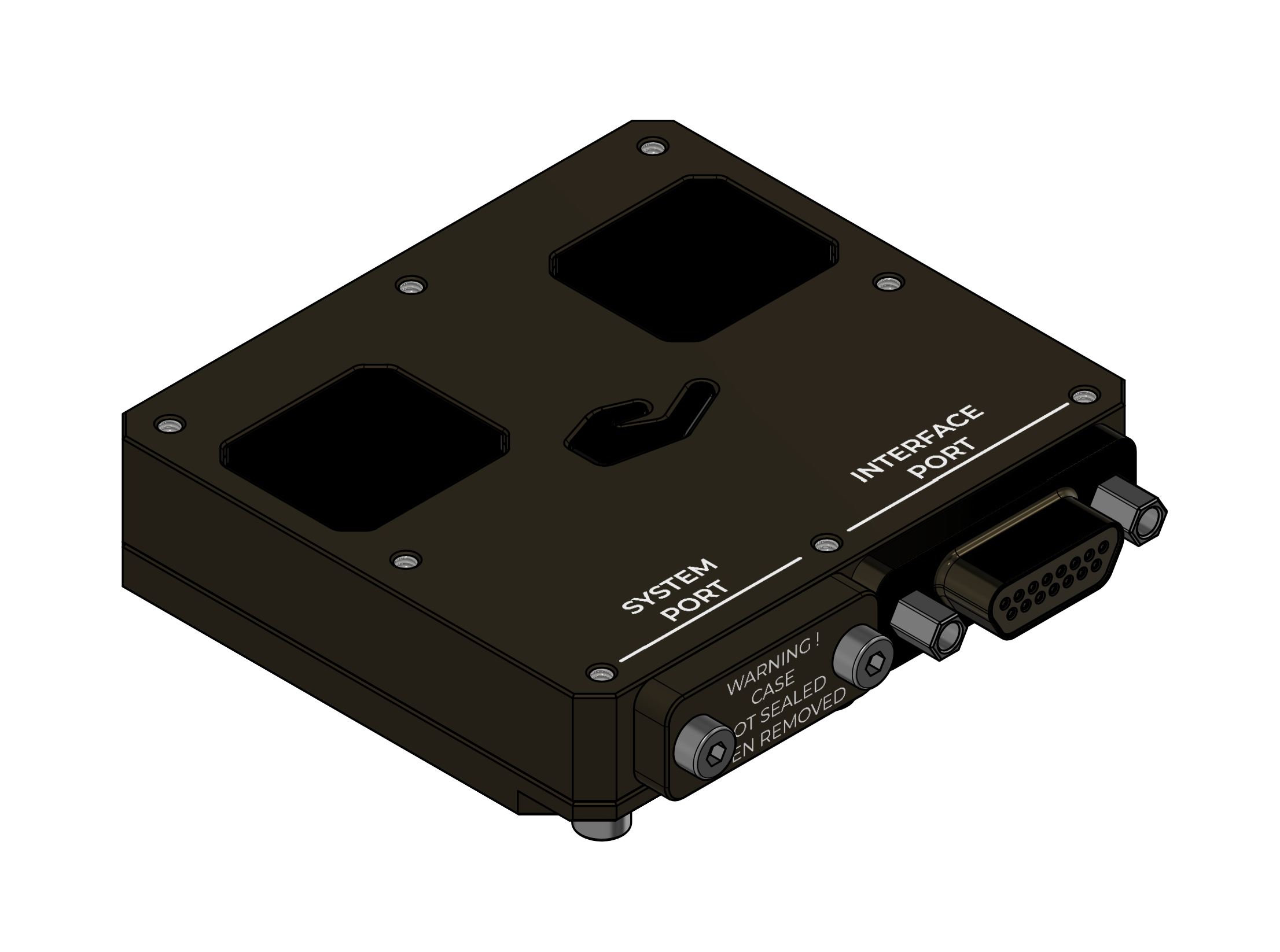
Figure: ULSDV-HLXS-G3-RXM Receiver
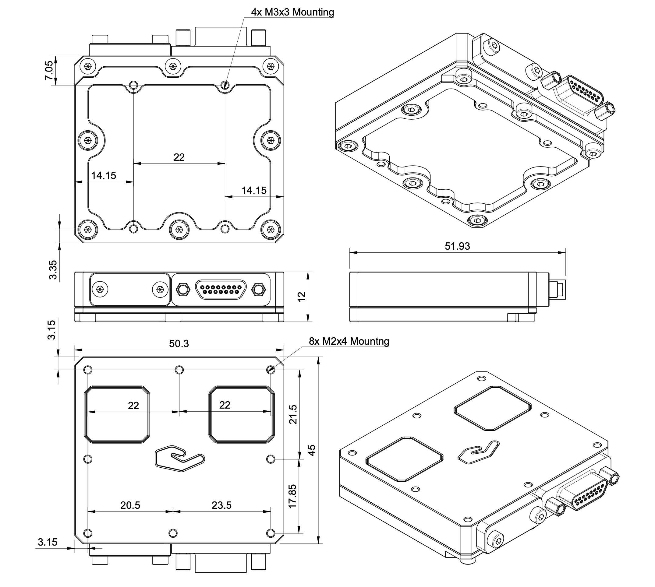
Figure: ULSDV-HLXS-G3-RXM Dimensions
- Receivers location and orientation: The device must be positioned with the optical elements facing downward. Ensure that the optical elements are not obstructed by foreign objects within the transmitter’s entire field of view.
- Install the receivers at least 0.5 meters apart; this will ensure reliable operation in MRX mode even if one of the receivers moves out of the system’s field of view. Typically, the first receiver (the one connected to the main autopilot) is located near the center of the landing point, and the second receiver is located at the tail. The maximum installation distance is 3 meters.
Configuration
Connecting Transmitter to PC
Use the ULS-XX-USB-RS422 adapter to connect the transmitter RS422 interface to a PC USB port for configuration and control via ULS-Tools software.
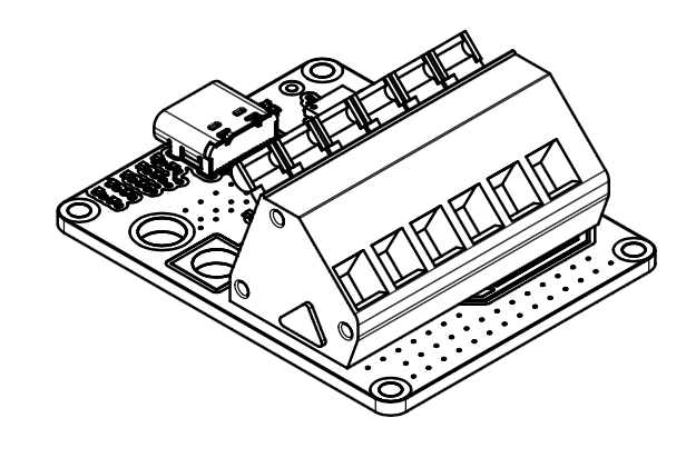
Figure: ULS-XX-USB-RS422 Ground Adapter
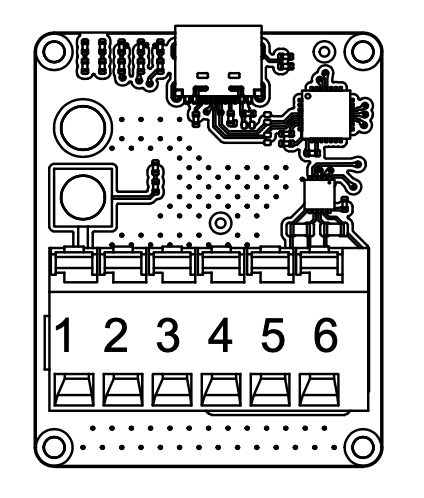
Figure: ULS-XX-USB-RS422 Adapter Pinout
Connecting Receiver to UART Autopilot
When the autopilot provides only a UART interface, use the ULS-XX-UART-RS422 onboard adapter between the receiver RS422 output and the autopilot UART port.
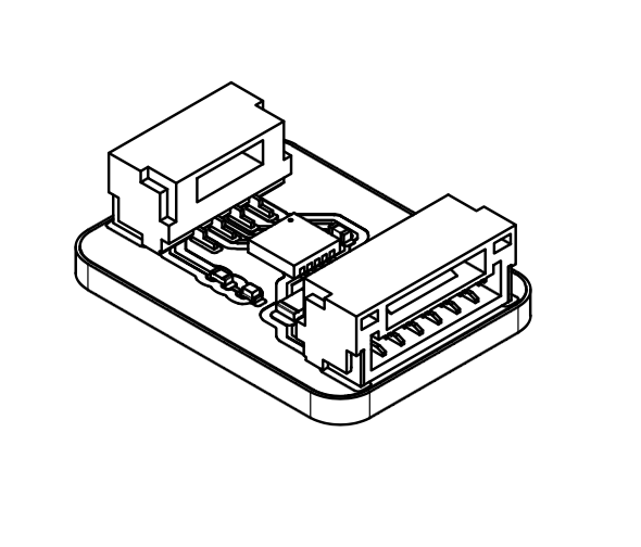
Figure: ULS-XX-UART-RS422 Onboard Adapter
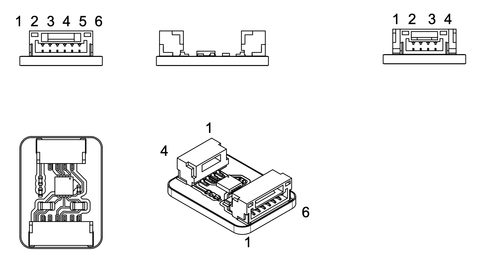
Figure: ULS-XX-UART-RS422 Onboard Adapter Pinout
Receiver Pinout
ULSDV-HLXS-G3-RXM Receiver pinout information.
Both receivers (Set A and Set B) are identical, equal-priority units. The pinout is the same for both.
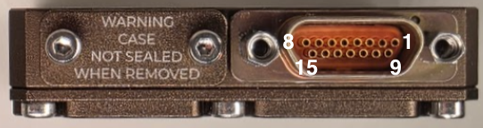
Figure: Receiver connector
| Pin | Function |
|---|---|
| 1 | + V supply +12V..+25V |
| 2 | C2H |
| 3 | C2L |
| 4 | GND - Ground connection |
| 5 | + V supply +12V..+25V |
| 6 | C1H |
| 7 | C1L |
| 8 | GND - Ground connection |
| 9 | + V supply +12V..+25V |
| 10 | RS422 Z |
| 11 | RS422 Y |
| 12 | RS422 A |
| 13 | RS422 B |
| 14 | GND - Ground connection |
| 15 | GND - Ground connection |
Table: ULSDV-HLXS-G3-RXM Connector Pinout When the autopilot provides only a UART interface, connect the receiver RS422 output to the autopilot via the ULS-XX-UART-RS422 onboard adapter.
For receiver setup unscrew protection part to get access to usb connector.
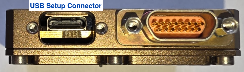
Figure: Receiver USB connector
Transmitter Pinout
ULSDV-XS-G3-TX Transmitter pinout information.
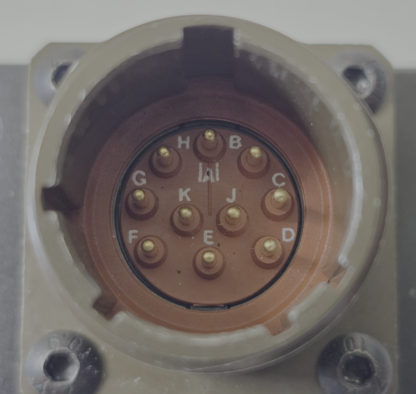
Figure: Transmitter connector
| Pin | Function |
|---|---|
| A | +V supply +18V…+27V |
| B | RS422 RX+ (A) |
| C | RS422 RX- (B) |
| D | RS422 TX+ (Y) |
| E | RS422 TX- (Z) |
| F | GND |
| G | C1L |
| H | C1H |
| J | GND |
| K | GND |
Table: Transmitter Connector Pinout (ULSDV-XS-G3-TX)
The transmitter connects to a PC via the ULS-XX-USB-RS422 ground adapter (USB side to PC, RS422 side to transmitter connector).
Device Configuration and Integration in ULS-Tools
Use the adapters listed in this manual to connect each device to a PC and complete configuration in ULS-Tools before field operation.
ULS-Tools Device Dashboard
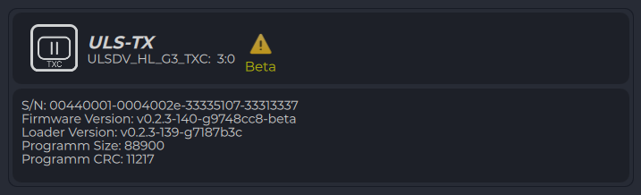
Figure: ULS-Tools Device Dashboard
Configure Transmitter
- Connect the transmitter through the ULS-XX-USB-RS422 adapter.
- Open transmitter settings and verify communication parameters.
- Set required operating parameters and click Apply Config.
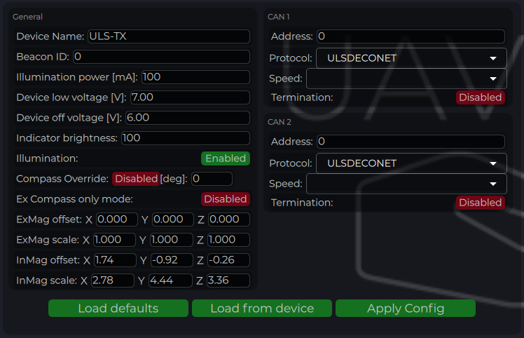
Figure: ULS-Tools Transmitter Configuration
| Parameter | Description |
|---|---|
| Device Name | Name shown for the transmitter in ULS-Tools. |
| Beacon ID | Transmitter iD to be transmitter to receiver over R signal (functionality under request) |
| Device Illumination Power | IR emitter power scaling (100 for nominal operation). |
| Device Low Voltage | Voltage level where low-voltage warning is activated. |
| Device Off Voltage | Voltage level where IR emitters are disabled to prevent over-discharge. |
| Indicator Brightness | Brightness level of the transmitter status LED indicator. |
| Illumination | Enables or disables transmitter emission during configuration and operation. |
| Compass Override [deg] | Fixed heading override for installations that require manual heading alignment. |
| External Compass Only | Forces system to use only external compass data when enabled. |
| Magnetometer Offset/Scale | Calibration values for internal or external (“Ex”) magnetometer. |
| CAN Address/Speed | CAN bus node address and bitrate settings. |
| CAN Protocol | Protocol selection (ULS DECENT with ULSBlitz messages supported) Custom protocols are possible |
| CAN Termination | If system has inbuilt termination resistor this option can activate it |
Table: Transmitter Configuration Parameters
Configure Receiver (RXM)
- Connect each receiver and configure one at a time.
- Set UART protocol/baud rate to match autopilot serial configuration.
- For dual-receiver installation, verify MRX-related parameters and offsets.
- Click Apply Config after each update.
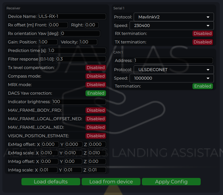
Figure: ULS-Tools Receiver Configuration
| Parameter | Description |
|---|---|
| Device Name | Name shown for the receiver in ULS-Tools. |
| Receiver Offset (Front, Right) [m] | Receiver position relative to vehicle reference point for MRX/yaw calculations. |
| Rx orientation | Receiver YAW installation orientation relative to vehicle front |
| Prediction Time [s] | Position prediction window used to smooth short signal interruptions. |
| Filter Response | Receiver position filter response tuning (higher is faster, lower is smoother). |
| Tx Level Compensation | Compensation for transmitter pan/tilt motion on moving platforms. |
| Compass Mode | Enables use of ground compass data in receiver calculations. |
| MRX Mode | Enables dual-receiver mode for yaw and redundancy features. |
| DACS Yaw Correction | Disable and enable Distance and Azimuth Correction System |
| Indicator Brightness | Brightness level of receiver status indicator. |
| Magnetometer Offset/Scale | Calibration values for internal or external (“Ex”) magnetometer. (under implementation) |
| CAN Address/Speed | CAN bus node address and bitrate settings. |
| CAN Protocol | Protocol selection (ULS DECENT with ULSBlitz messages supported) Custom protocols are possible |
| CAN Termination | If system has inbuilt termination resistor this option can activate it |
| UART Protocol | Protocol selection for autopilot communication (for example MavlinkV2). |
| UART Baud Rate | Serial baud rate; must match autopilot serial port settings. |
| UART Termination | If system has inbuilt termination resistor this option can activate it |
Table: Receiver Configuration Parameters
Compass Calibration (Ground Unit)
After installation, check compass behavior and perform calibration if required.
- Press Reset calibrations.
- Rotate the ground unit through multiple orientations to fill calibration charts.
- Press Apply calibration and Apply Config.
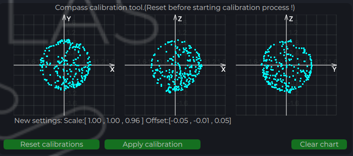
Figure: ULS-Tools Compass Calibration
Integration Verification in ULS-Tools
- Confirm live device telemetry is visible in charts.
- Verify stable IMU and system parameter traces before flight tests.
- Confirm receiver link and valid position updates prior to autopilot integration tests.
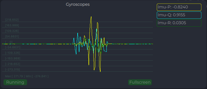
Figure: ULS-Tools System Parameters Chart
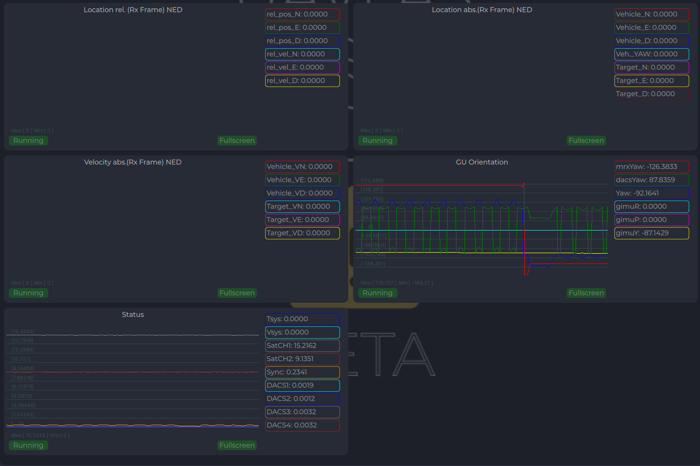
Figure: ULS-Tools Receiver Charts
Integration Instructions for Ardupilot Based Systems
Preparing for Integration
- Download the latest version of ULS-Tools (Beta). It is recommended to connect all devices to a PC and update firmware for all UAVLAS devices before proceeding.
- Update the autopilot to the latest Arducopter version.
- Configure the transmitter in ULS-Tools
- Configure both receivers in ULS-Tools
The system communicates with Ardupilot using the MavlinkV2 protocol (supports MAV_FRAME_BODY_FRD).
Autopilot Configuration
Setup PLND Section
| Param | Value | Comment |
|---|---|---|
| PLND_ENABLED | 1 | Enable the precision landing module |
| PLND_TYPE | 1 | Use type = 1 to enable UAVLAS sensor over the companion computer driver |
Table: Ardupilot PLND Section Parameters All other PLND parameters should remain at defaults, or be set according to your vehicle requirements.
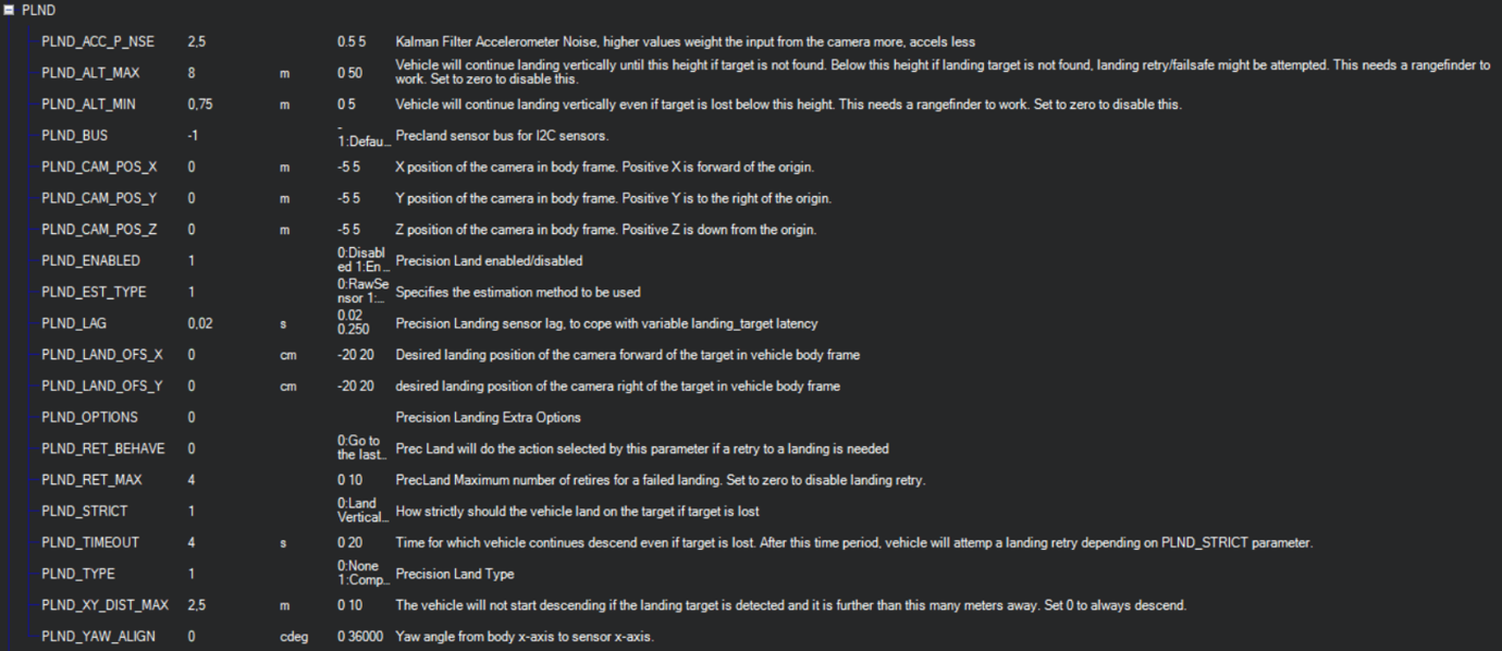
Figure: PLND Configuration Example
Set Up Serial Communication in SERIALx Section
| Param | Value | Comment |
|---|---|---|
| SERIAL2_BAUD | 230 | Baud rate — must match the receiver UART baud rate setting |
| SERIAL2_OPTIONS | 0 | Default |
| SERIAL2_PROTOCOL | 2 | MAVlink2 protocol |
Table: Ardupilot SERIALx Section Parameters Set up serial stream rates in the SRx section. The sensor requires the following data from the autopilot:
| Param | Value | Comment |
|---|---|---|
| SR2_EXTRA1 (or MAV2_EXTRA1) | 20 | Attitude stream at 20 Hz — required for compass mode yaw orientation |
| SR2_POSITION (or MAV2_POSITION) | 20 | Optional — Vehicle LOCAL_POSITION_NED stream at 20 Hz for absolute target position calculation |
Table: Ardupilot SRx Stream Rate Parameters
Check Setup
When configuration and wiring are correct, GPS is available, and the receiver is in the field of view of the transmitter, you will see the LANDING_TARGET MAVLink message in the MAVLink Inspector (Mission Planner example shown):
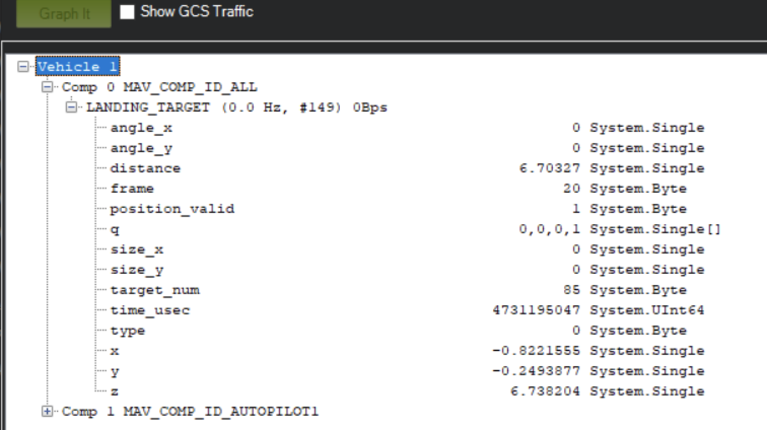
Figure: LANDING_TARGET Message in MAVLink Inspector
Setup Precision Loiter Mode
Attach any unused switch to the PrecLoiter option to enable precision loiter mode:
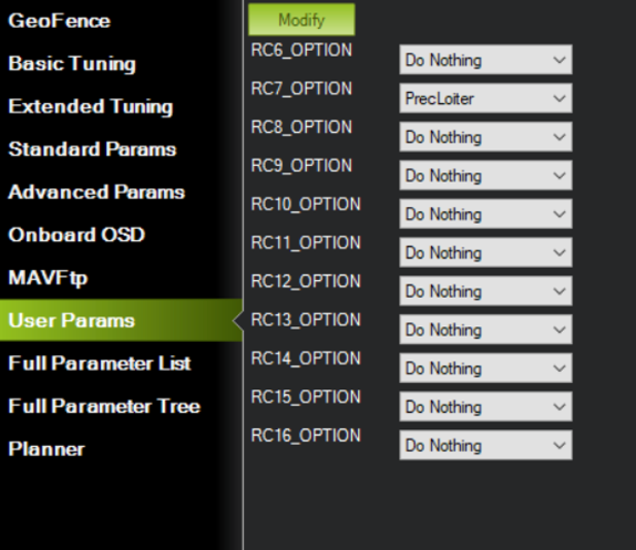
Figure: PrecLoiter Switch Configuration
Activate the switch and confirm messages “PrecLoiter: LOW” and “PrecLoiter: HIGH” appear. After a test flight above the target, check telemetry for PL offset data.
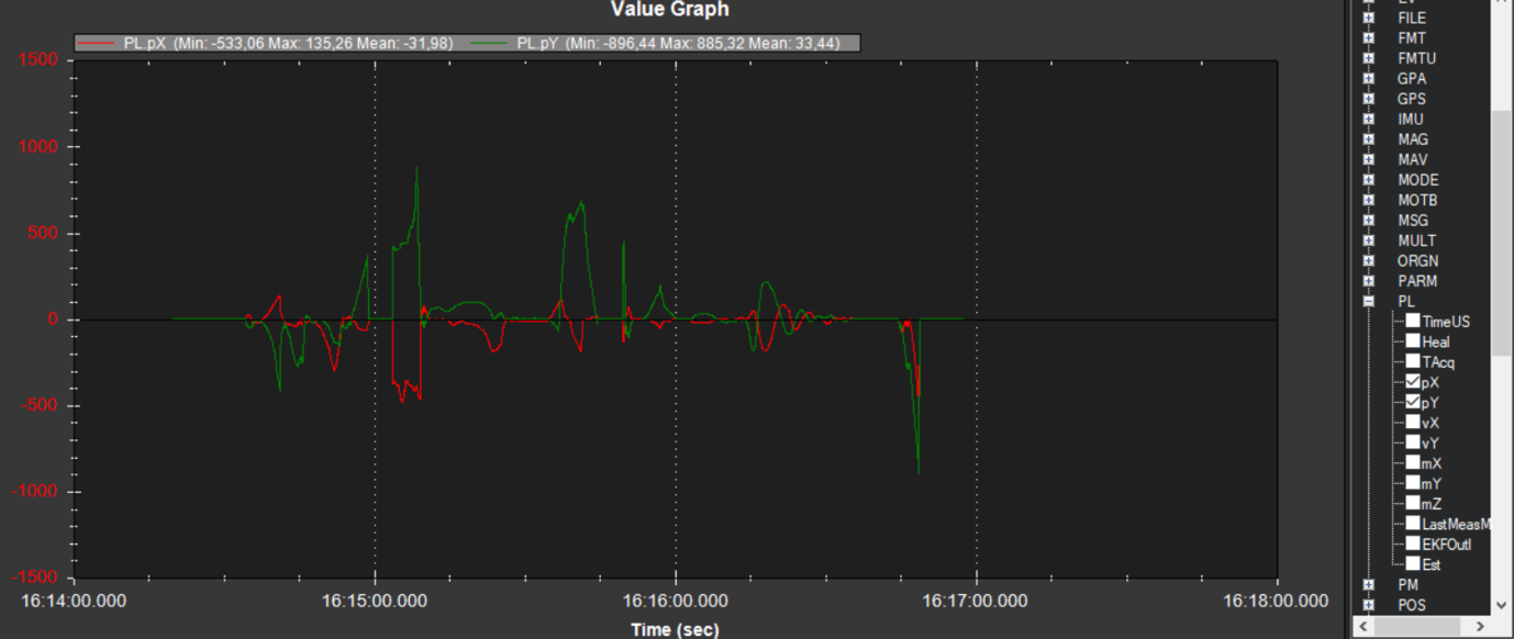
Figure: Telemetry Data Showing PL Offsets
PID Tuning
In case of oscillations or instability during landing, check the PID parameters in Ardupilot Extended Tuning.
It is recommended to tune Position XY, Velocity XY, and Loiter Speed for the best performance:
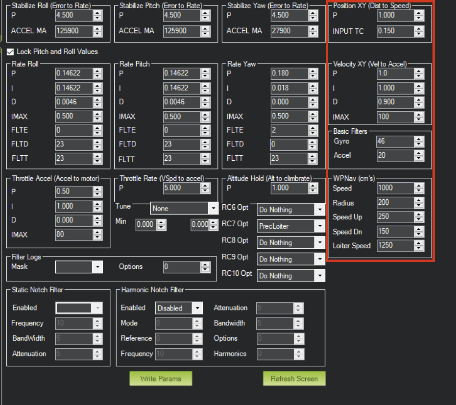
Figure: Ardupilot Extended Tuning Parameters
For additional information, see the Ardupilot documentation at https://ardupilot.org/ardupilot/
Integration Instructions for PX4 Based Systems
Preparing for Integration
- Download the latest version of ULS-Tools (Beta). It is recommended to connect all devices to a PC and update firmware for all UAVLAS devices before proceeding.
- Update the autopilot to the latest PX4 version.
- Configure the transmitter in ULS-Tools.
- Configure both receivers in ULS-Tools.
The system communicates with PX4 using the MavlinkV2 protocol (supports MAV_FRAME_LOCAL_NED).
Configure PX4 Autopilot
Values are provided as an example (Pixhawk4-mini AP):
| PX4 Parameter | Value | Comment |
|---|---|---|
| MAV_1_CONFIG | TELEM/SERIAL4 | Requires reboot to apply the next parameters |
| MAV_1_FORWARD | Enabled | Forward MAVLink messages |
| MAV_1_MODE | Onboard | Set link mode to onboard |
| SER_TEL4_BAUD | 460800_8N1 | Must match the UART baud rate set in the receiver configuration |
Table: PX4 Autopilot Configuration Parameters
Running and Testing
After configuration and wiring, power up the drone and transmitter. In QGroundControl, go to Analyze Tools → MAVLink Inspector and check for the LANDING_TARGET MAVLink message.
If the vehicle is providing a LOCAL_POSITION_NED message to the UAVLAS system and is hovering over the beacon, the field position_valid = 1 will appear in LANDING_TARGET.
To perform precision landing, create a flight plan and enable the Precision Landing option on the landing waypoint.
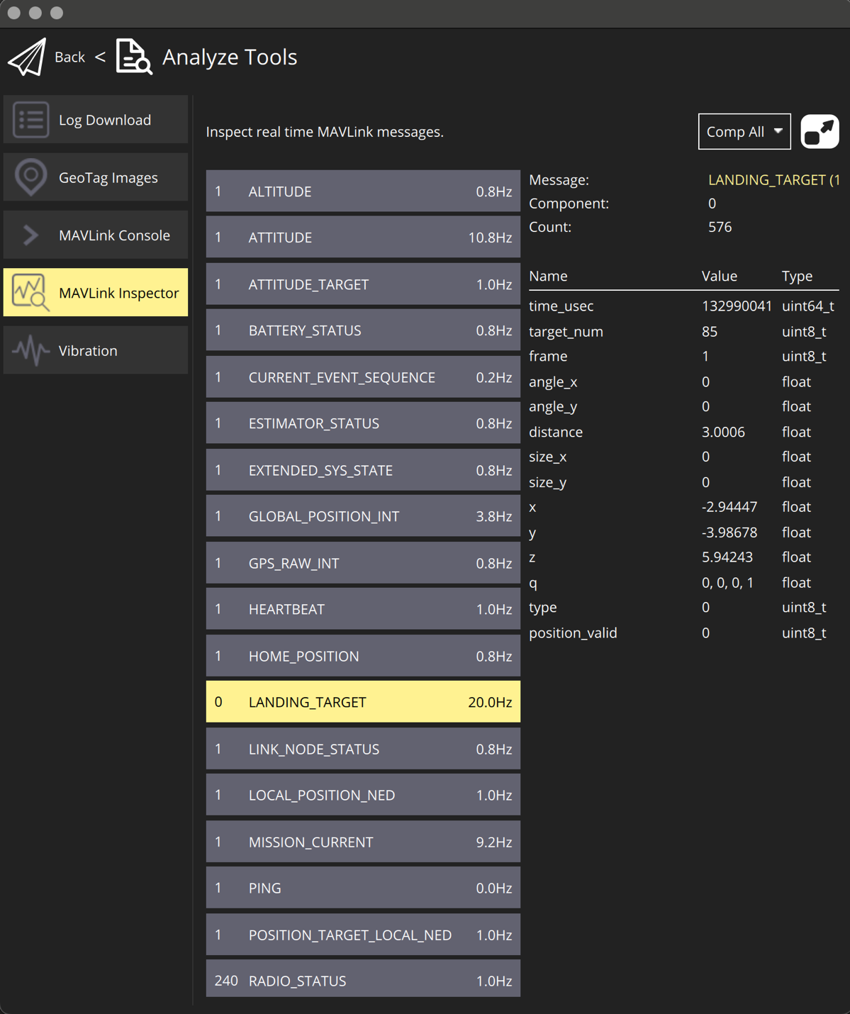
Figure: LANDING_TARGET Message in QGroundControl
For additional information, see the PX4 documentation at https://docs.px4.io/main/en/
Operating Instructions
- Power sequence: Power device after all connectors are plugged in before powering.
- Link check procedure: Link can be checked from the configuration system during system installation, as well as during operation using a third-party device via the appropriate protocols.
- Landing and approach operation notes: The vehicle’s control system independently decides on the appropriate action based on the status of the landing system. The UAVLAS system acts as a sensor—the procedure for handling abnormal situations during operation remains the responsibility of the unmanned vehicle’s control system.
- Equal-priority RXM behavior in MRX mode: Both receivers have the same priority, and either one can be used to receive system status data.
- Tethered operation: verify that the tether cable stays inside the transmitter centre through hole over the full range of tether movement.
Service and Support
The device requires no maintenance throughout its service life.
Appendices
Technical Reference
| Parameter | Value |
|---|---|
| Distance range (m) | 30m…50m |
| Working angle (deg) | 60 |
| Data update frequency (Hz) | 20 |
| Optical emission | IR 940nm, pulsed |
| Receiver architecture | 2 identical RXM receivers with same priority |
| Redundancy mode | Dual-RXM redundancy |
| MRX yaw estimation method | Triangular method |
| Operating mode | Tethered drone, stationary or slow-moving platform |
Table: Common Specification
| Parameter | Value |
|---|---|
| Field of view (deg) | 95 |
| Dimensions (mm) | 50x54 |
| Weight (g) | 50 |
| Power consumption (W) | 10 |
| Supply voltage (V) | +12V…+24V |
| Interfaces | CAN,USB,RS422 |
Table: ULSDV-HLXS-G3-RXM Receiver Specifications Both RXM units (Set A and Set B) are the same hardware and share the specification above.
| Parameter | Value |
|---|---|
| Field of emitting (deg) | 30 (60 in Wide Field) |
| Centre through hole (mm) | 47 x 47 |
| Dimensions (mm) | 254 x 214 |
| Weight (g) | 1960 |
| Power consumption (W) | 20W |
| Supply voltage (V) | +18V..+24V |
| Interfaces | CAN, RS422 |
Table: ULSDV-XS-G3-TX Transmitter (Ground) Specifications
Change Control
All changes to this document must be reviewed and approved by the relevant technical leads and stakeholders
References
- ULSDC-PBDS190426-ULS-XSpot-G3-Datasheet
- ULSDC-PBICD190426-ULS-XSpot-G3-ICD