ULSToolsX User Manual
ULSDC-PBUM021126 · version 0.2.0 · issued November 3, 2026
The numbered PDF is the controlled copy: download it from the portal.
Introduction
Purpose
ULSToolsX is the configuration and diagnostics tool for UAVLAS devices. Use it to connect to devices, read their live status on a dashboard, change and save their settings, and update their firmware.
This manual explains how to use the application and how to read each dashboard widget.
Scope
This manual covers the application’s screens, its widgets, and the values those widgets display. It does not explain what each device’s settings do or which values to choose. For those, see the Operation Manual of the product:
- ULS-Heli-G3: ULSDC-PBOM110426
- ULS-XSpot-G3: ULSDC-PBOM190426
About the Figures
All figures come from the real application connected to simulated devices. The values, serial numbers and firmware names shown (such as SIM-1.0) are simulated, and the firmware versions on the firmware screens are samples. Your devices will show their own values.
Each device describes its own settings and dashboard, so the tabs, card titles and values you see depend on the device and its firmware.
Installation
ULSToolsX runs in a browser with nothing to install, or as an installed application. See Web Version below for the browser. For an installation file, contact UAVLAS support at support@uavlas.com.
| Platform | File | How to install |
|---|---|---|
| macOS | Universal .dmg | Open the file and drag the application to Applications. The build is unsigned, so the first time, right-click the application and choose Open. |
| Windows | x64 .zip | Extract the archive and run the application from the extracted folder. |
| Android | .apk | Install the file on the device. Android may ask you to allow installation from this source. |
Table: Installation Files
Web Version
The web version is at utx.tools.uavlas.com.
The browser decides what the application may use. The first time, select Choose… on the card, then pick the port or device in the browser’s dialog. Serial ports you have already approved are listed as “Granted port 1”, and so on.
Interface Overview
Tabs and Links
A link is one open connection to a device or a bus. Each link has its own tab at the top of the window, so you can work with several at once.
- + (tooltip “Connect another device”) opens the connection page in a new tab.
- × on a tab closes that link (tooltip “Close link”).
- The icon at the right end of the tab bar shows two links next to each other (tooltips “Side by side” and “One link at a time”). It appears when the window is at least 1100 pixels wide.
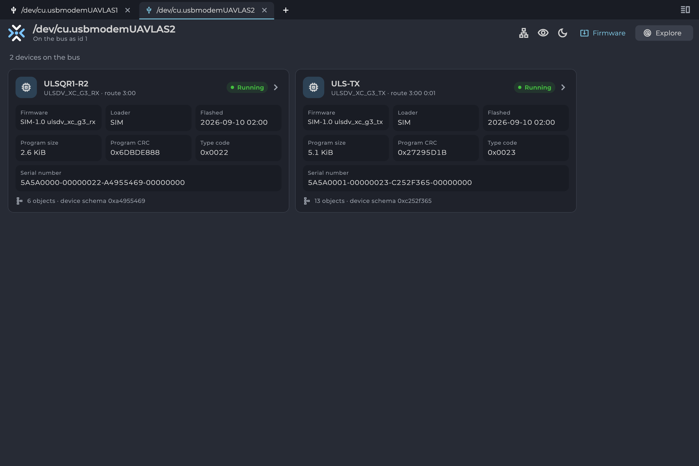
Figure: Two Links Open in Tabs
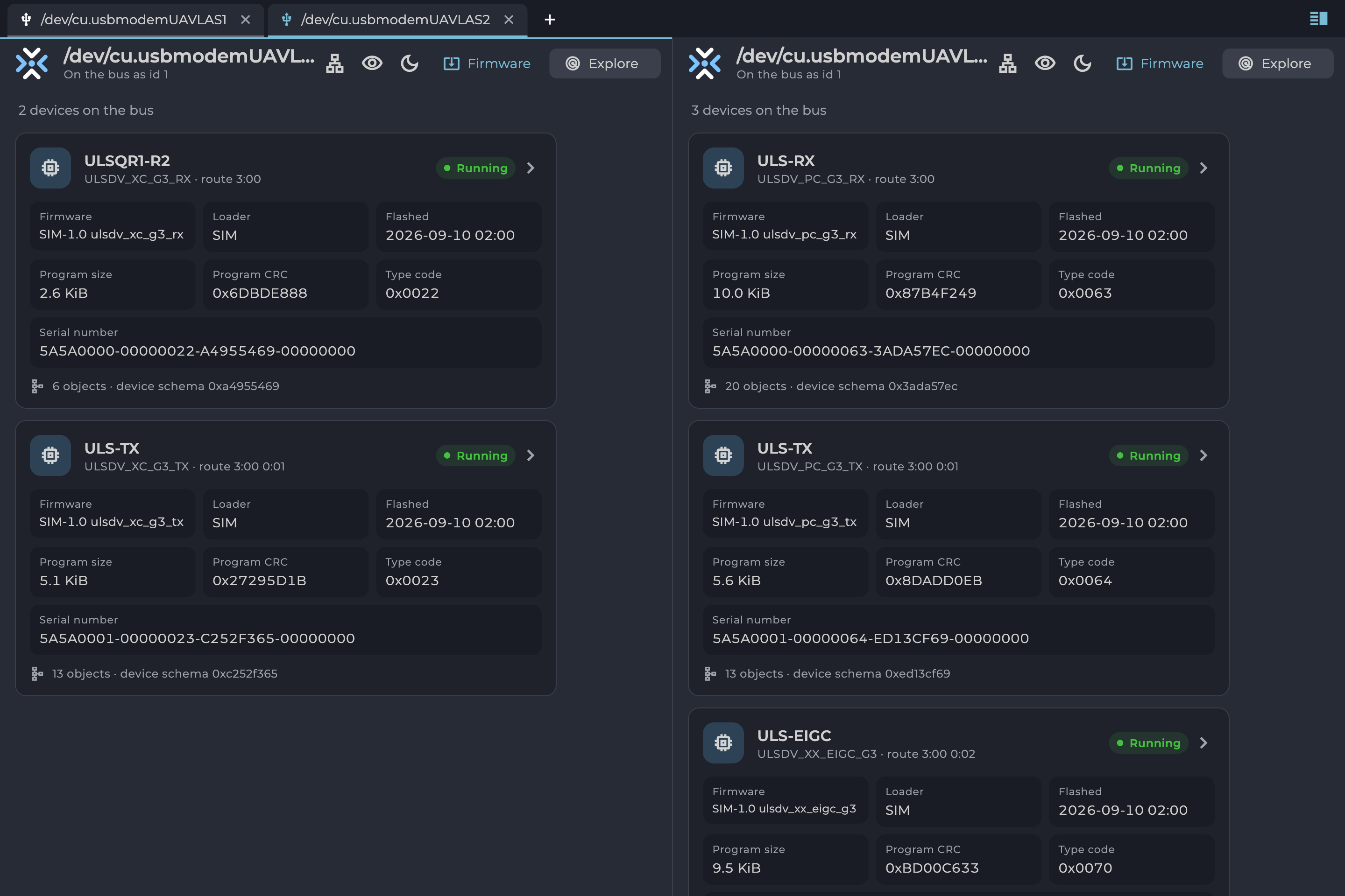
Figure: Two Links Side by Side
Theme
The theme button in the app bar switches between System, Light and Dark. Figures in this manual use the dark theme.
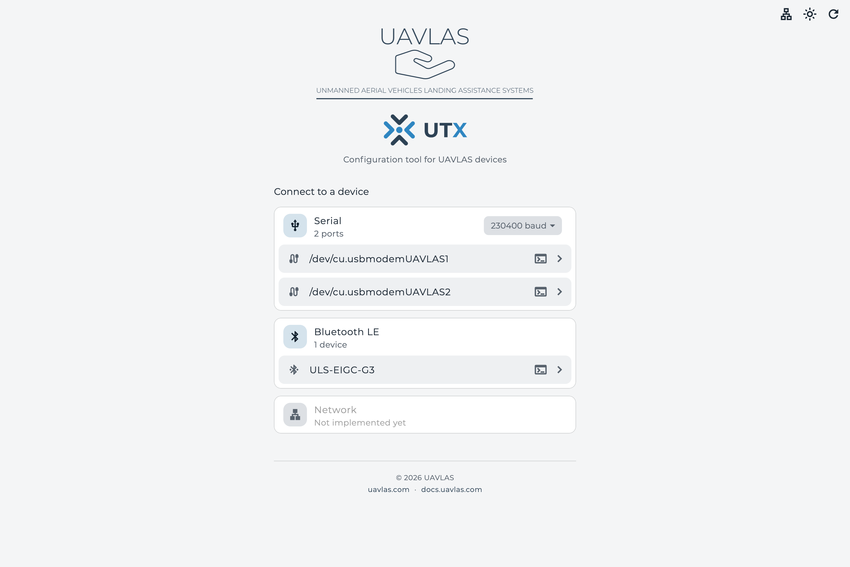
Figure: Connection Page in the Light Theme
User Levels
The user level decides how much of each device you see. The level applies to the whole application, and the application remembers it. Choose it from the button in the app bar.
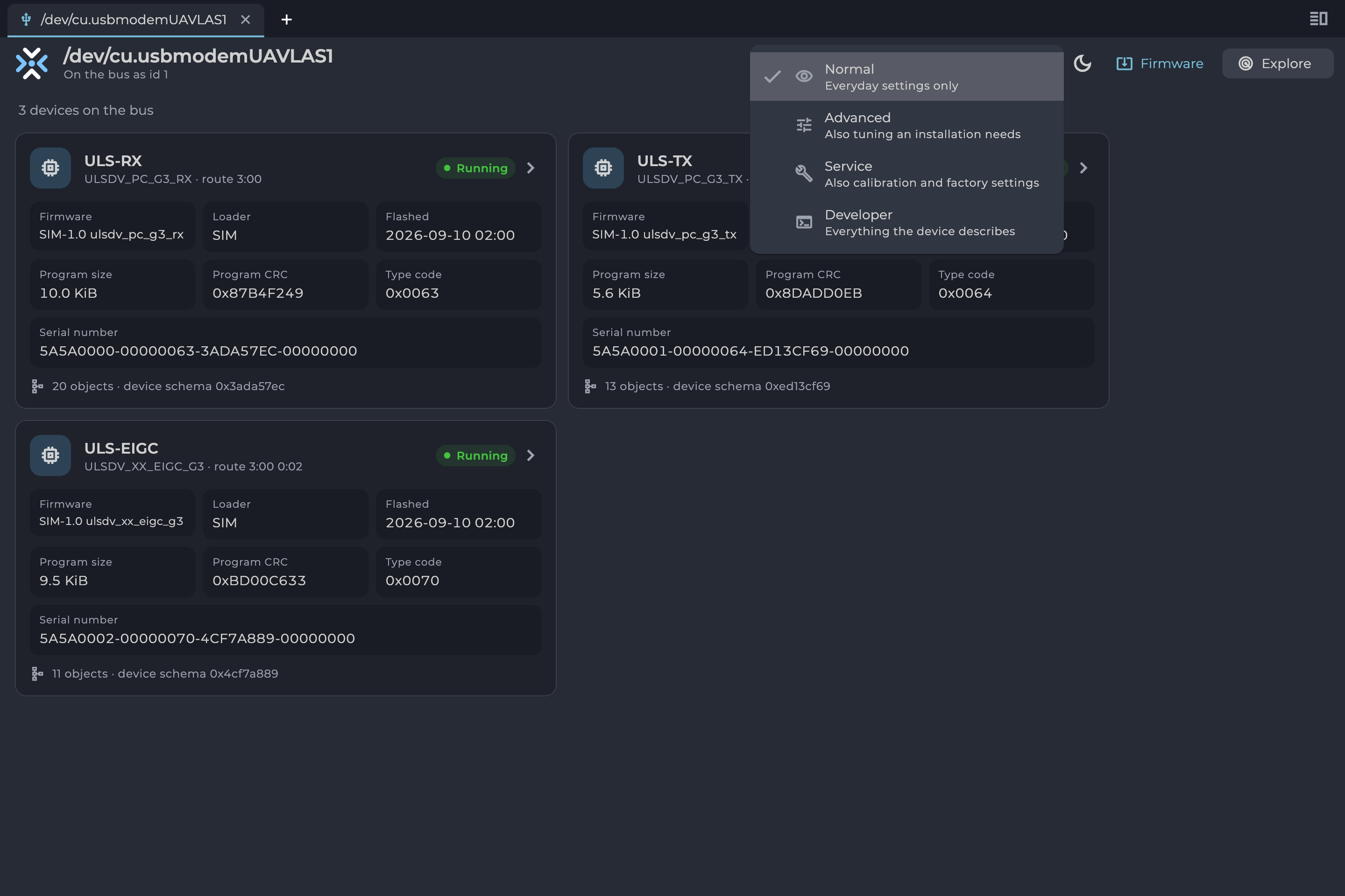
Figure: User Level Menu
| Level | Shows |
|---|---|
| Normal | Everyday settings only. |
| Advanced | Also tuning an installation needs. |
| Service | Also calibration and factory settings. Adds the event log tab. |
| Developer | Everything the device describes. Adds the ADC capture tab. |
Table: User Levels An object’s header shows how many fields your level hides, for example “24 hidden”.
Connecting Devices
Connection Page
The connection page lists everything the application can connect to, grouped by connection type. Select a row to connect.
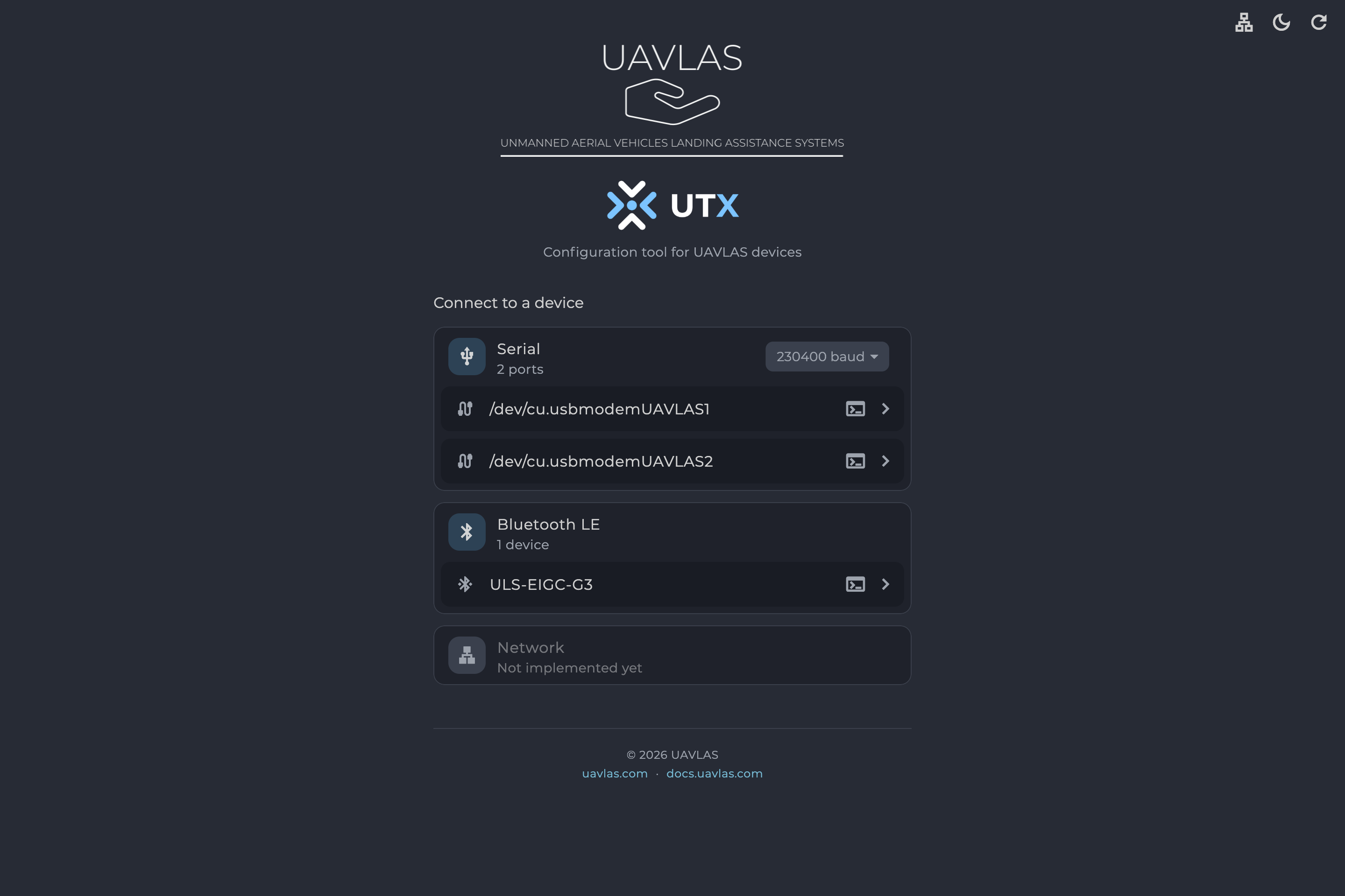
Figure: Connection Page
| Card | Use |
|---|---|
| Serial | Ports on this computer, including USB. Names depend on the operating system, such as /dev/cu.usbmodem… on macOS. |
| Bluetooth LE | Devices found over Bluetooth. Real devices show their signal strength and address on the row. |
| Network | Not implemented yet. |
Table: Connection Types If a card reads “Searching…” the search is still running. “No devices found” means the search finished empty, and “Not available on this platform” means this connection type does not work on your platform. Use the refresh button in the app bar to search again.
Connecting over Serial
- Connect the device and power it.
- Set the baud rate on the Serial card. The default is 230400 baud.
- Select the port.
USB ports ignore the baud rate setting, so you only need it for a real serial connection.
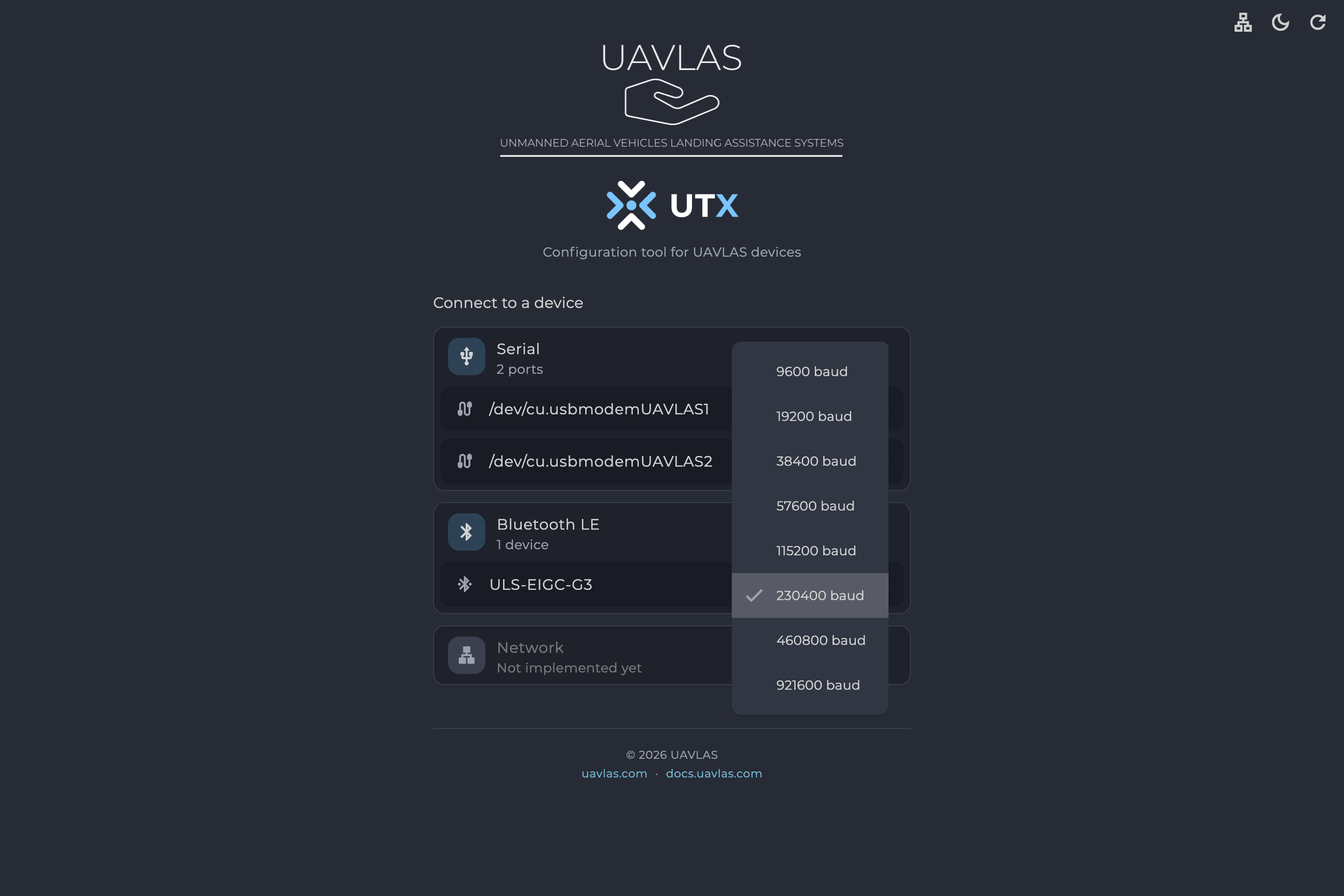
Figure: Baud Rate List
Connecting over Bluetooth
Select the device on the Bluetooth LE card. The rest of the application works the same as over serial.
Devices behind a Bridge
You only connect to one device, but you see every device on its bus. When a device connected to the computer is also on CAN with other devices, those devices appear in the device list too, and you can configure and update them over the same link.
Several Links
To add a link, select + and choose another port. Rows of open links read “Connected · show its tab”; select one to go to its tab.
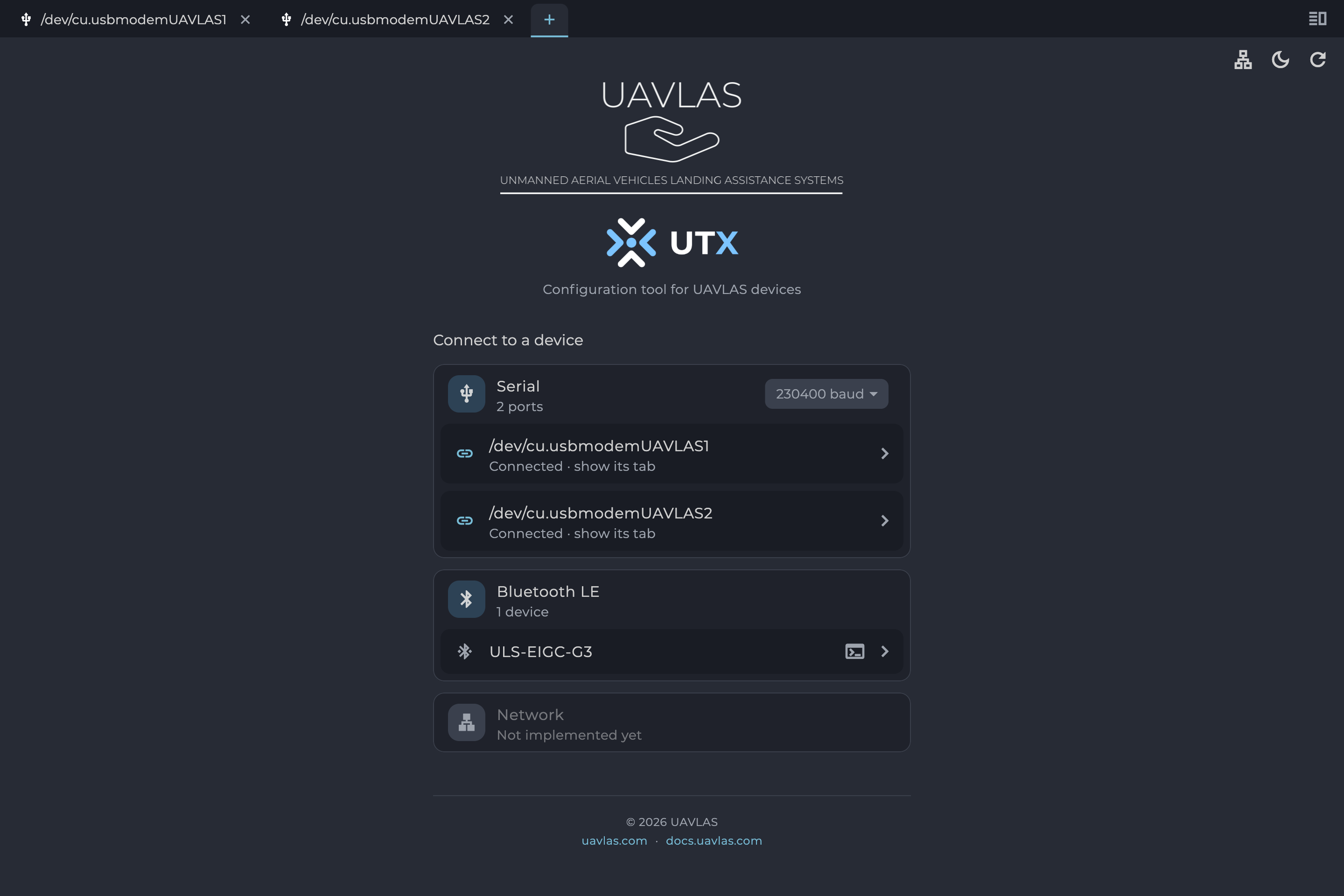
Figure: Connection Page with Two Links Open
Device List
After you connect, the link’s tab shows the devices on the bus. The header reads “Joining the bus…” and then “On the bus as id N”, and the list fills as devices answer. Explore asks the bus for its devices again.
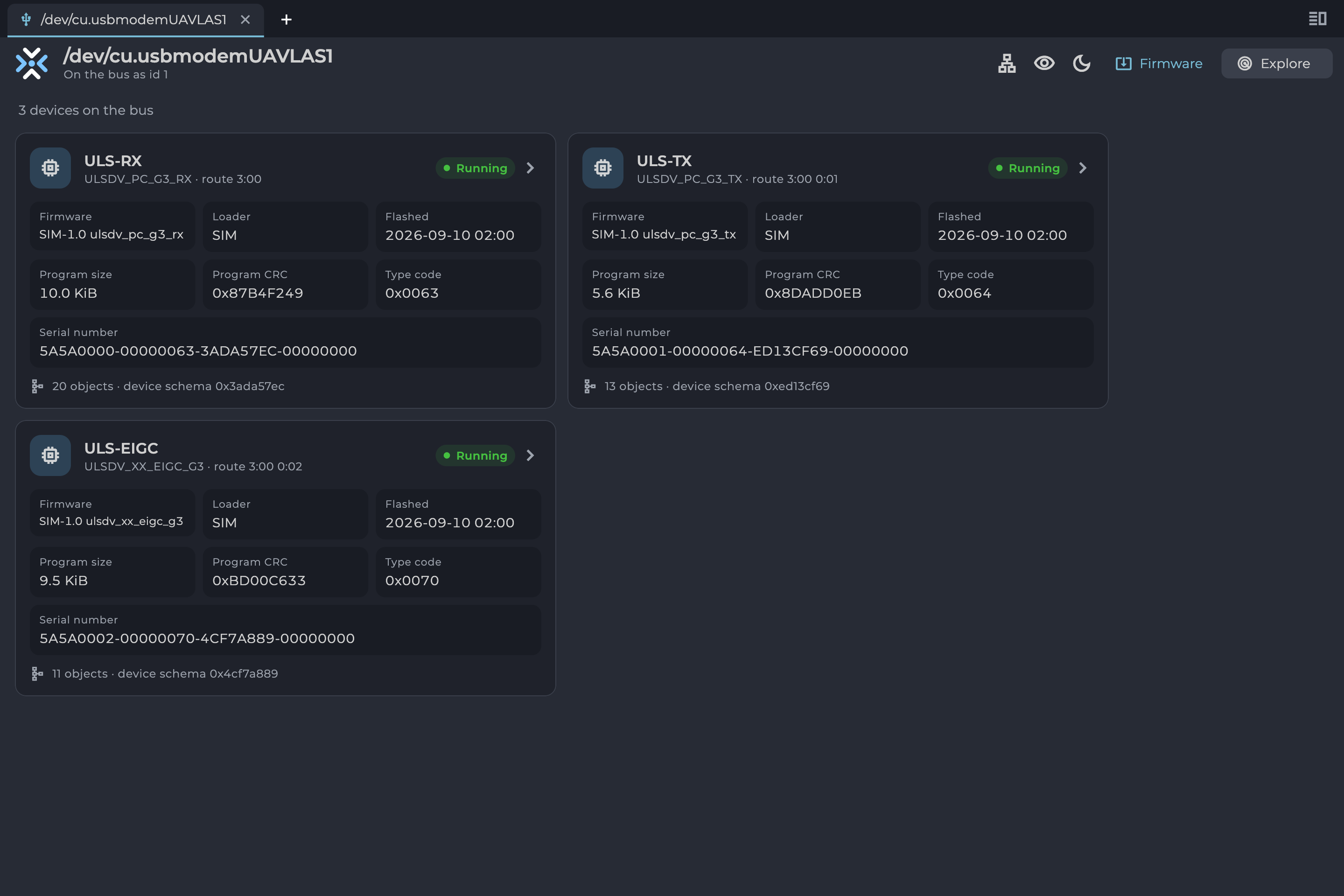
Figure: Device List
Each device has a card. Select a card to open the device.
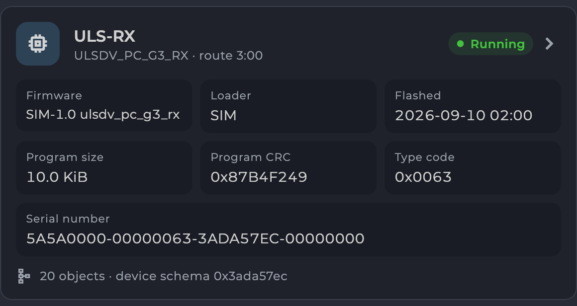
Figure: Device Card
| Field | Meaning |
|---|---|
| Name and type | The name set on the device, its type name and its route on the bus. |
| Running / Bootloader | Whether the device is running its application or sitting in its loader. |
| Firmware | Version of the running firmware. |
| Loader | Version of the bootloader. |
| Flashed | When the firmware was written. |
| Program size | Size of the firmware. |
| Program CRC | Checksum of the firmware. |
| Type code | Numeric device type. |
| Serial number | The unit’s unique serial number. |
| Schema line | Objects the device describes and the schema in use. |
Table: Device Card Fields While the application fetches a device’s description, the schema line shows progress (“Asking for schema…”, then “schema a/b”). “No schema — signature only” means the device gave no description, so the application can show only its signature.
Device Page
Tabs
The device page has one tab per part of the device:
| Tab | Content |
|---|---|
| dashboard | Live widgets. See Dashboard and Widget Reference. |
| capture | ADC capture, on devices that support it, at the Developer level. |
| log | Event log, on devices that support it, at the Service level and above. |
| Object tabs | One per data object, such as Signature, Status, Links and Config. |
| schema | The device’s own description of its objects. |
Table: Device Page Tabs If the device stops answering, the page reads “The device stopped answering; showing the last values read. Waiting for it to come back…”. Values on screen are then old.
Viewing an Object
An object’s header shows its layout name, address, size, access type, the age of the last read and any hidden field count. Live keeps reading the object four times a second, and read-only objects start with it on. Read now (the refresh icon) reads it once and discards any unwritten edits.
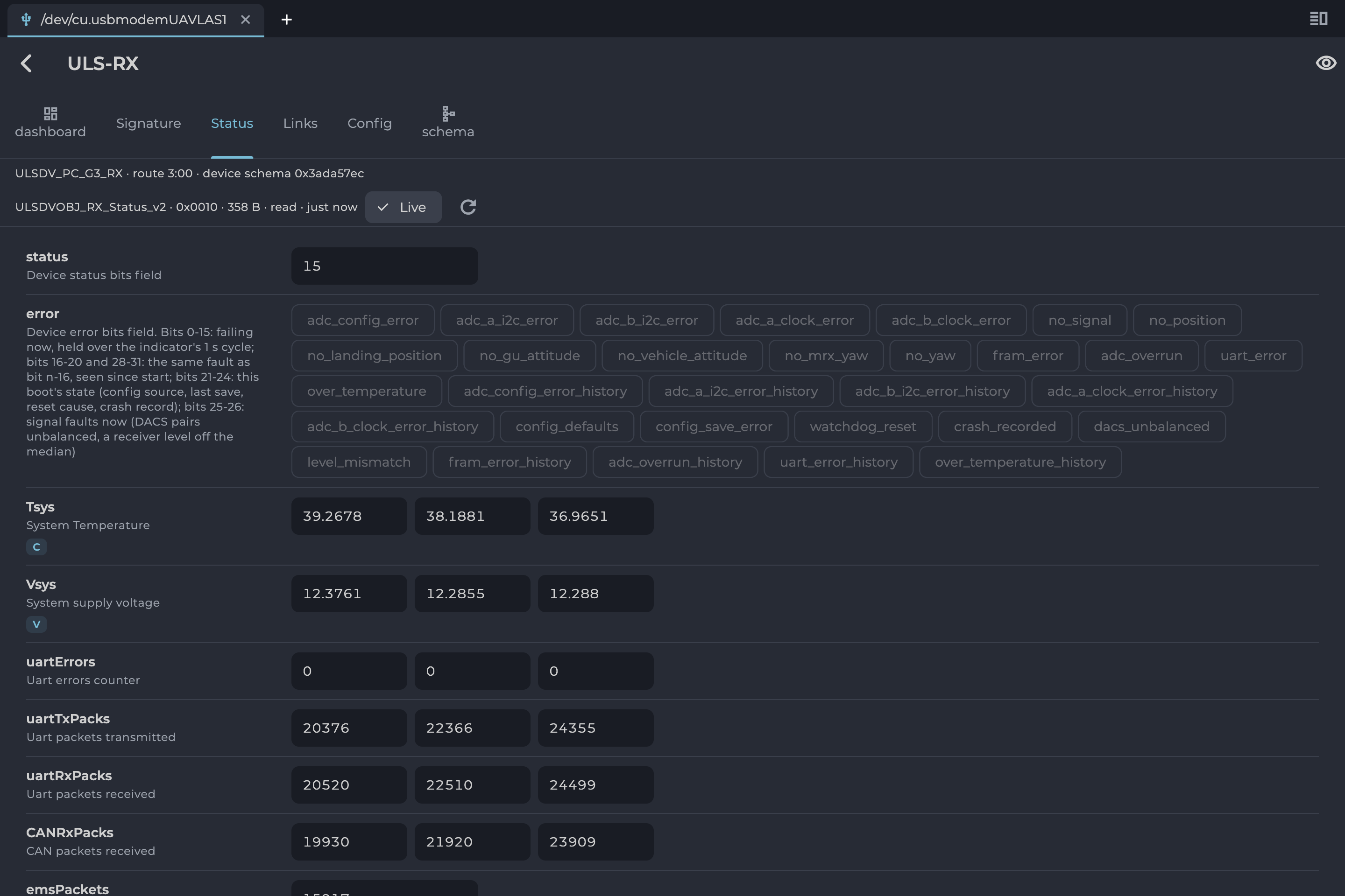
Figure: Read-Only Object with Live On
Changing Settings
This section explains how to change a setting. For what each setting does, see the product’s Operation Manual.
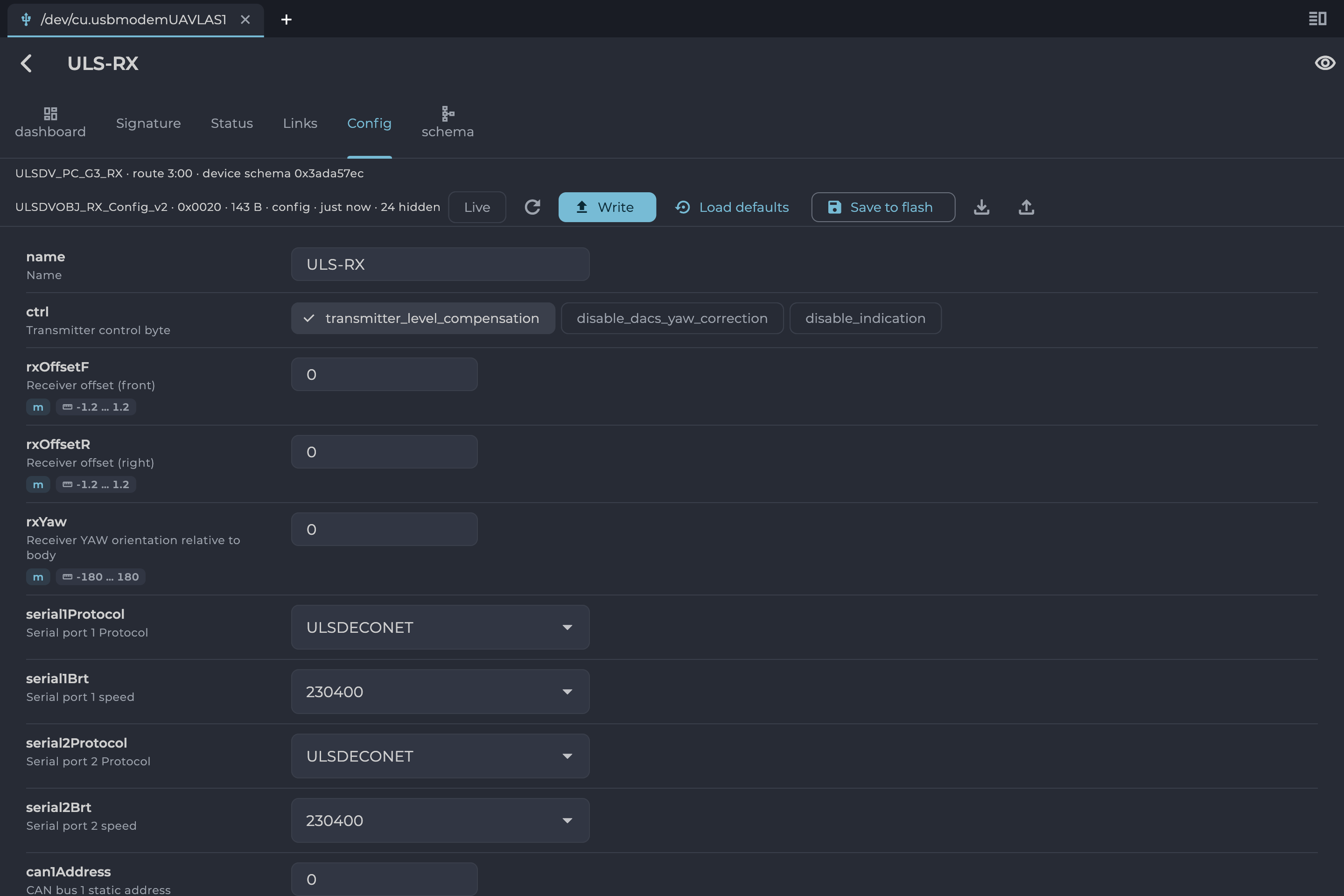
Figure: Configuration Object
- Change a value. The field is highlighted, and the button becomes “Write 1 change”.
- Select Write to send your changes to the device.
- Select Save to flash to keep them after a power cycle.
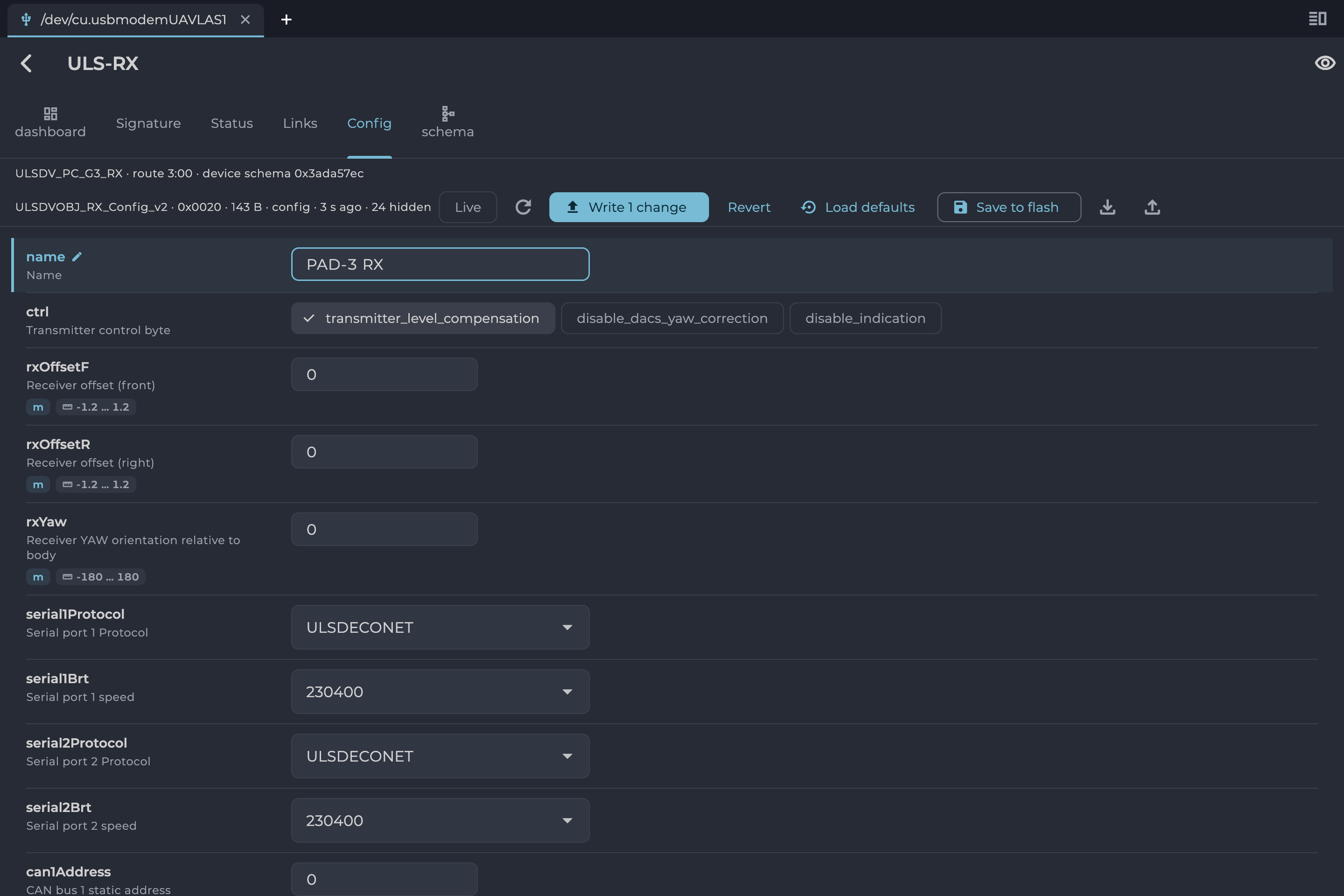
Figure: Configuration Object with an Unwritten Change
| Button | Action |
|---|---|
| Write | Sends your changes to the device. They last until the device restarts, unless you save them. |
| Revert | Discards changes you have not written. |
| Load defaults | Loads the default values. Write, then save to flash to keep them. |
| Save to flash | Stores the device’s current settings permanently. |
| Download icon | “Save configuration to a file”. |
| Upload icon | “Load configuration from a file”. |
Table: Configuration Buttons
Configuration Files
A configuration file (.ulscfg) holds all of a device’s configuration objects. Use one to back up a unit or to copy settings to another.
Loading a file writes nothing by itself. The application compares the file with the device and lists each difference with a tick box. Untick anything you do not want, then select Write N changes. Afterwards it offers Save to flash.
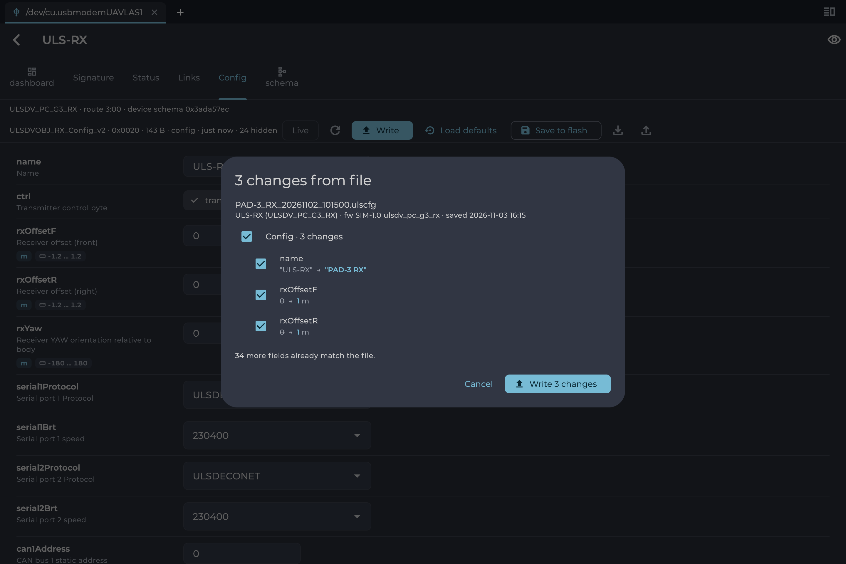
Figure: Comparing a Configuration File with the Device
Schema Tab
The schema tab lists the device’s type, its schema details and all its objects with their address, type, access and size. It is mainly useful for support and integration work.
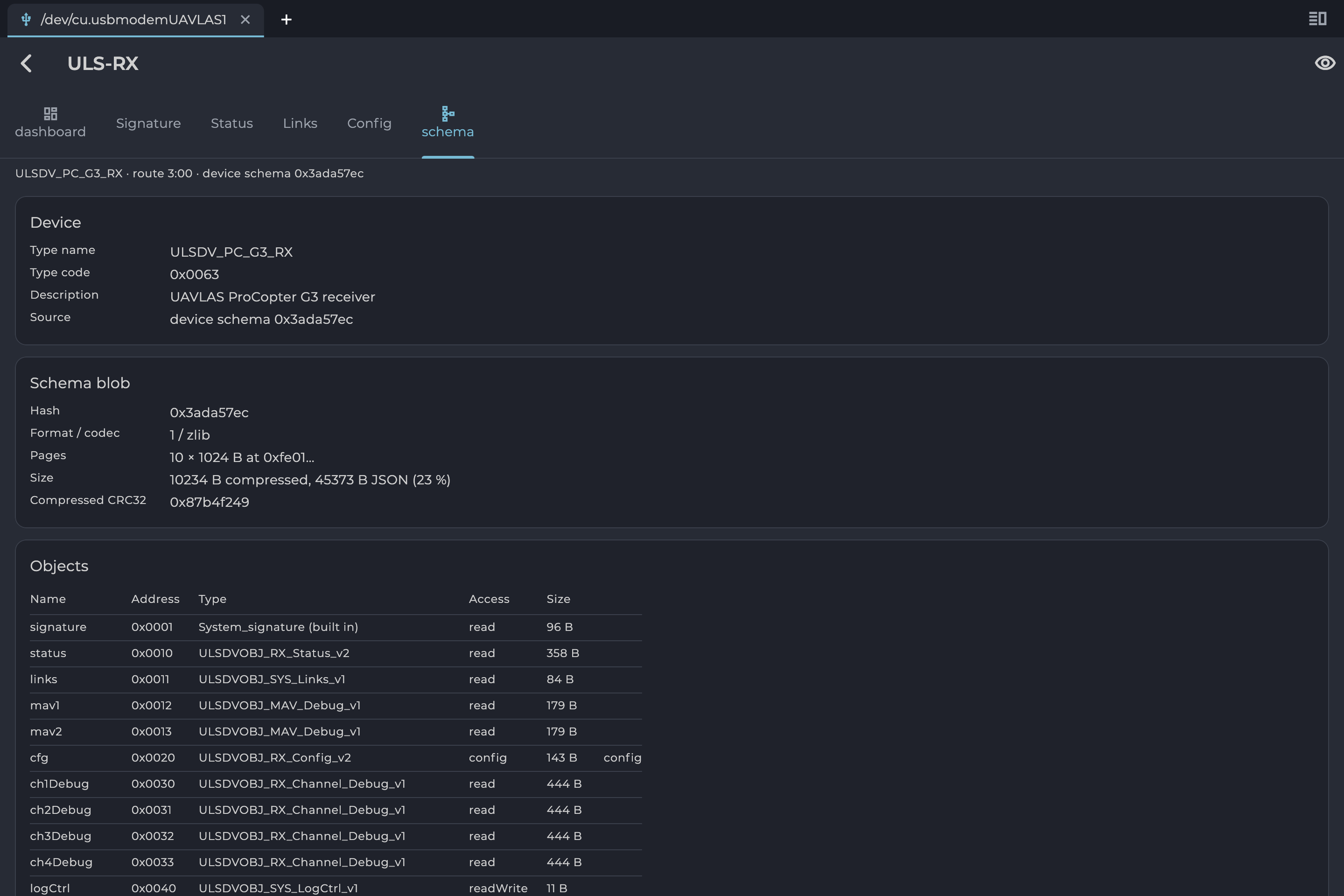
Figure: Schema Tab
Updating Firmware
Before You Start
- Power the device from a stable supply. It must stay powered and connected until it has restarted.
- The application downloads firmware from the UAVLAS server, so it needs internet access unless you load a file.
Choosing a Build
Select Firmware on the device list. The page lists builds on the selected channel and the devices on this link.
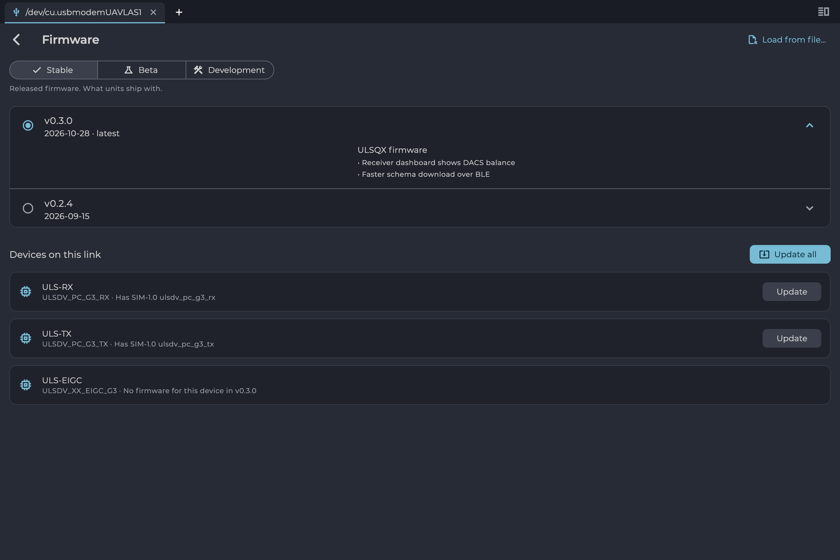
Figure: Firmware Page, Stable Channel
| Channel | Contents |
|---|---|
| Stable | Released firmware. What units ship with. |
| Beta | Release candidates, for testing before a release. |
| Development | Every development build. May be broken. |
Table: Firmware Channels Select a build with its radio button. The newest is marked “latest”. Expand a build to read its changes.
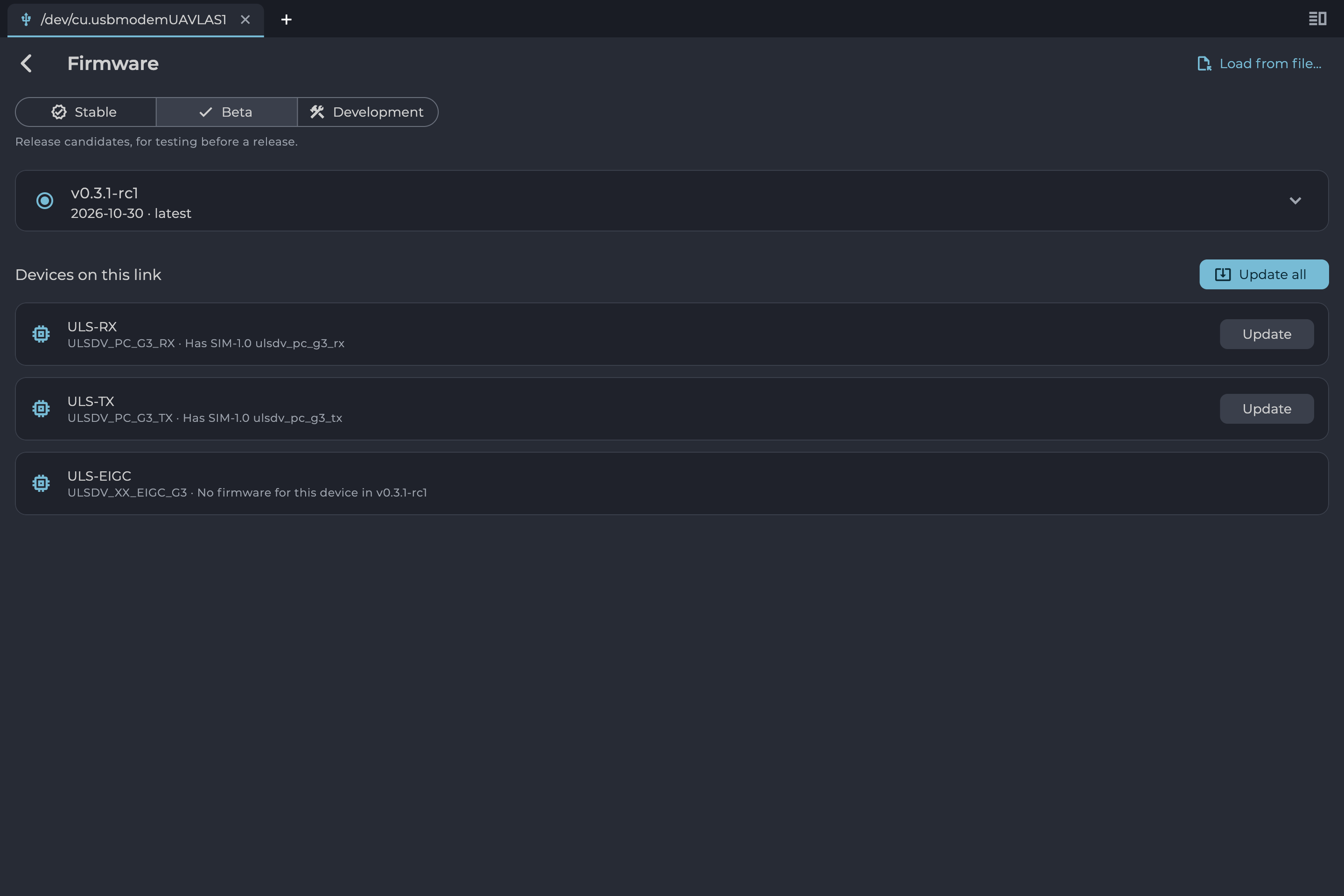
Figure: Beta Channel
Using a Firmware File
To install a file you already have, such as one from UAVLAS support, select Load from file… and choose the .ulsbndl file. The application checks the file’s integrity first. A banner shows the file’s version, name and image count, and the close button (tooltip “Back to the server”) returns to the channels.
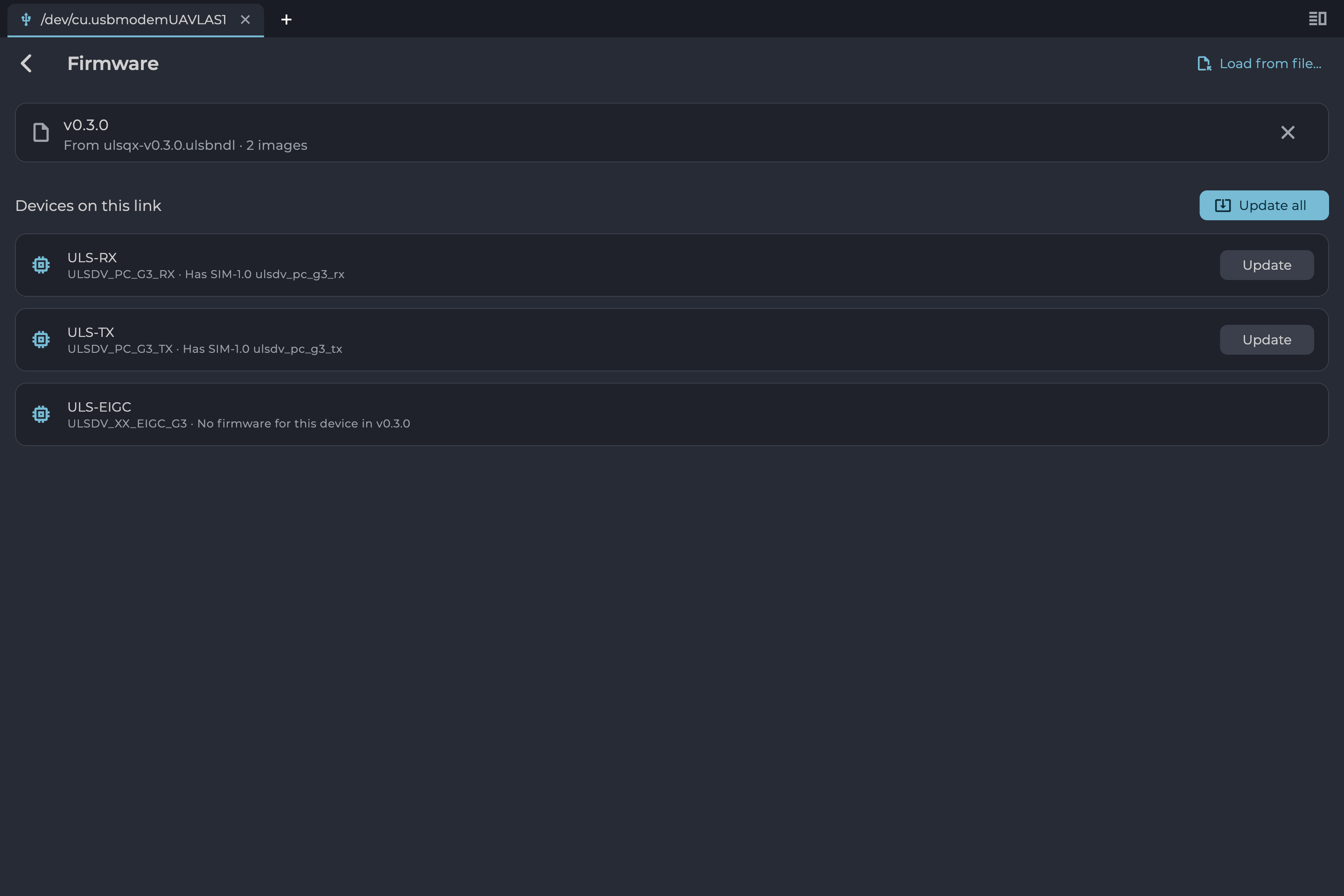
Figure: Firmware Loaded from a File
Installing
Each device row shows where it stands:
| Status | Meaning |
|---|---|
| “Has X” | The device runs version X, and the selected build differs. |
| “Up to date” | The device already runs the selected build. Reinstall is available. |
| “Firmware unknown” | The device did not report its version. |
| “No firmware for this device in X” | The selected build has nothing for this device type. |
Table: Device Status on the Firmware Page
- Select Update on a device, or Update all for every device the build covers.
- Read the confirmation and select Install.
- Wait for the update to finish. Update all updates devices one at a time.
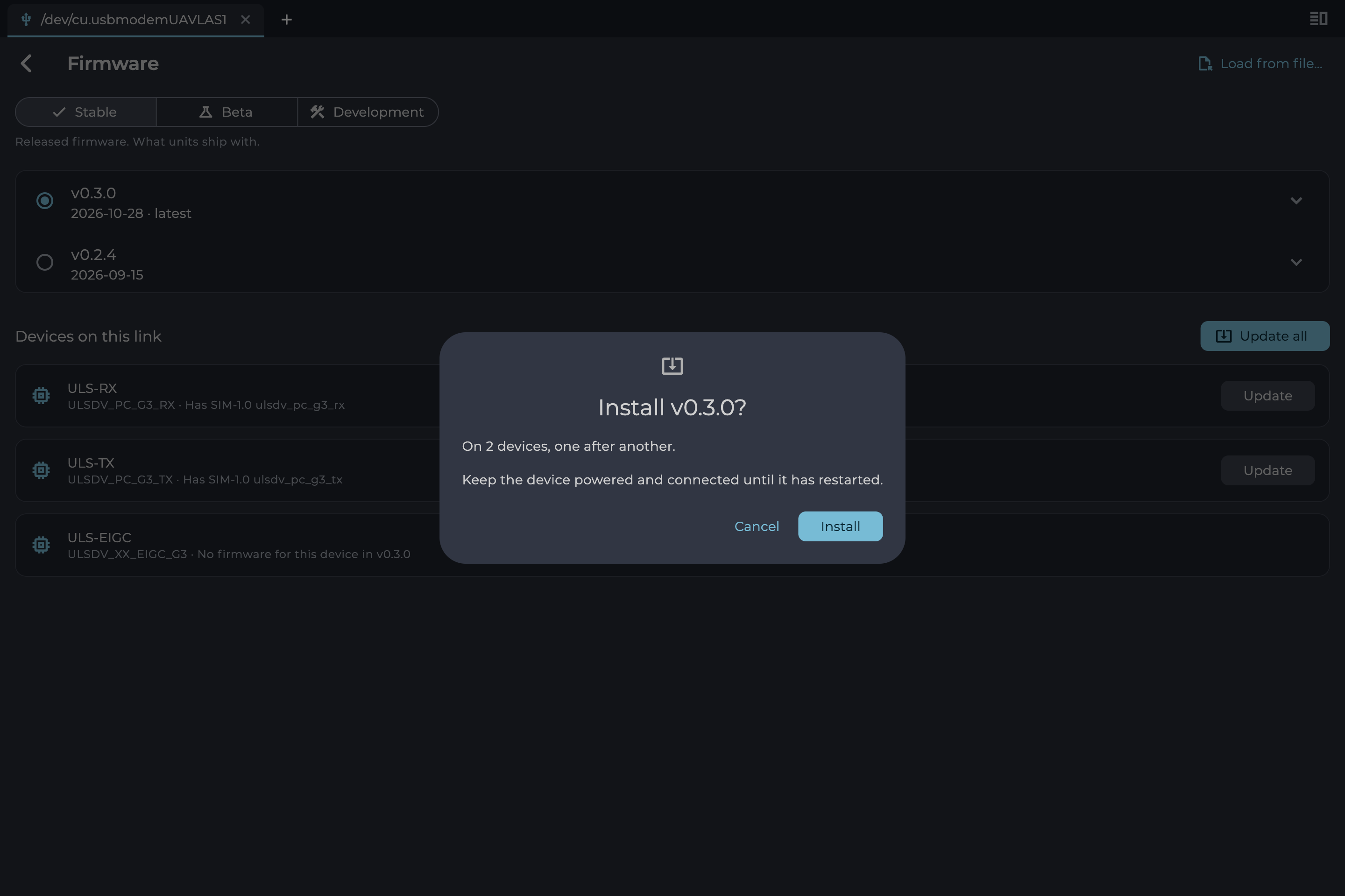
Figure: Install Confirmation
Installing from Beta or Development adds a warning, such as “This is a beta build, not a release.”
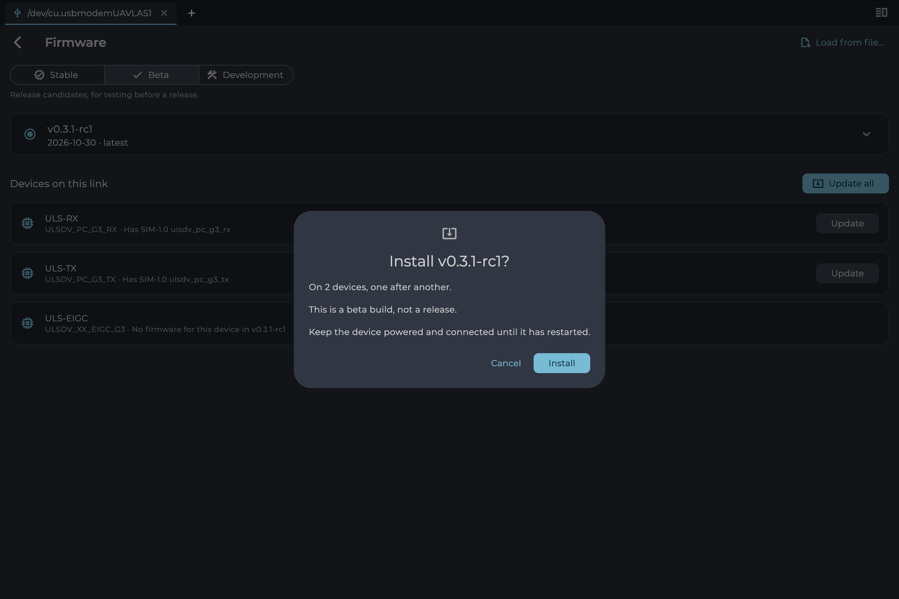
Figure: Install Confirmation for a Beta Build
Progress appears on each device’s row. The stages are Preparing, Restarting into the loader, Erasing, Writing, Finishing and Restarting, ending in Updated or Failed.
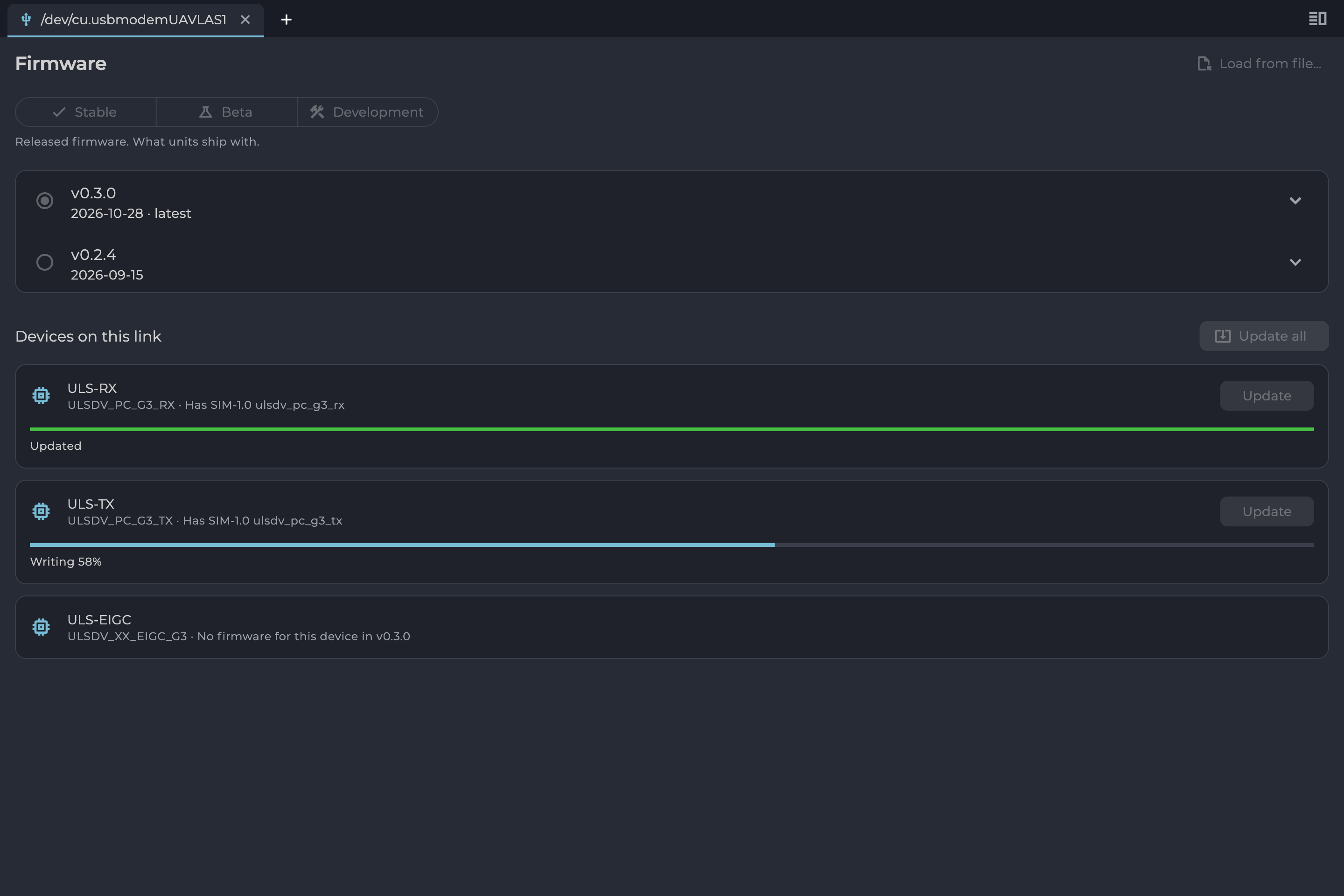
Figure: Update in Progress
If an Update Fails
The failed device shows the reason in red, and any others keep their results. Check power and the connection, then select Update to try again. See Troubleshooting for what each message means.
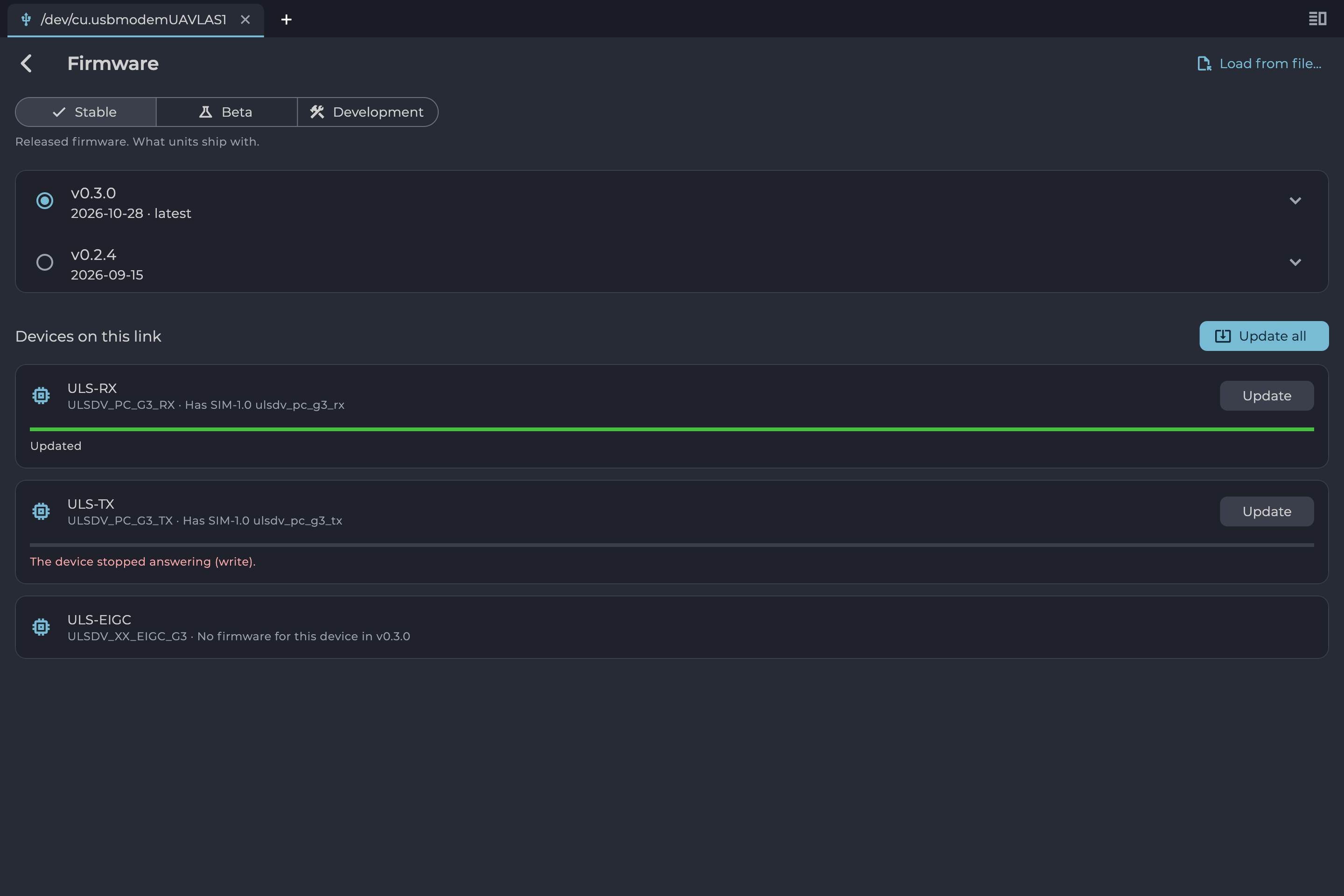
Figure: One Device Updated, One Failed
Dashboard
The dashboard tab shows a device’s live data as widgets, grouped into titled sections. The device decides which widgets appear. The grid changes its number of columns with the window width.
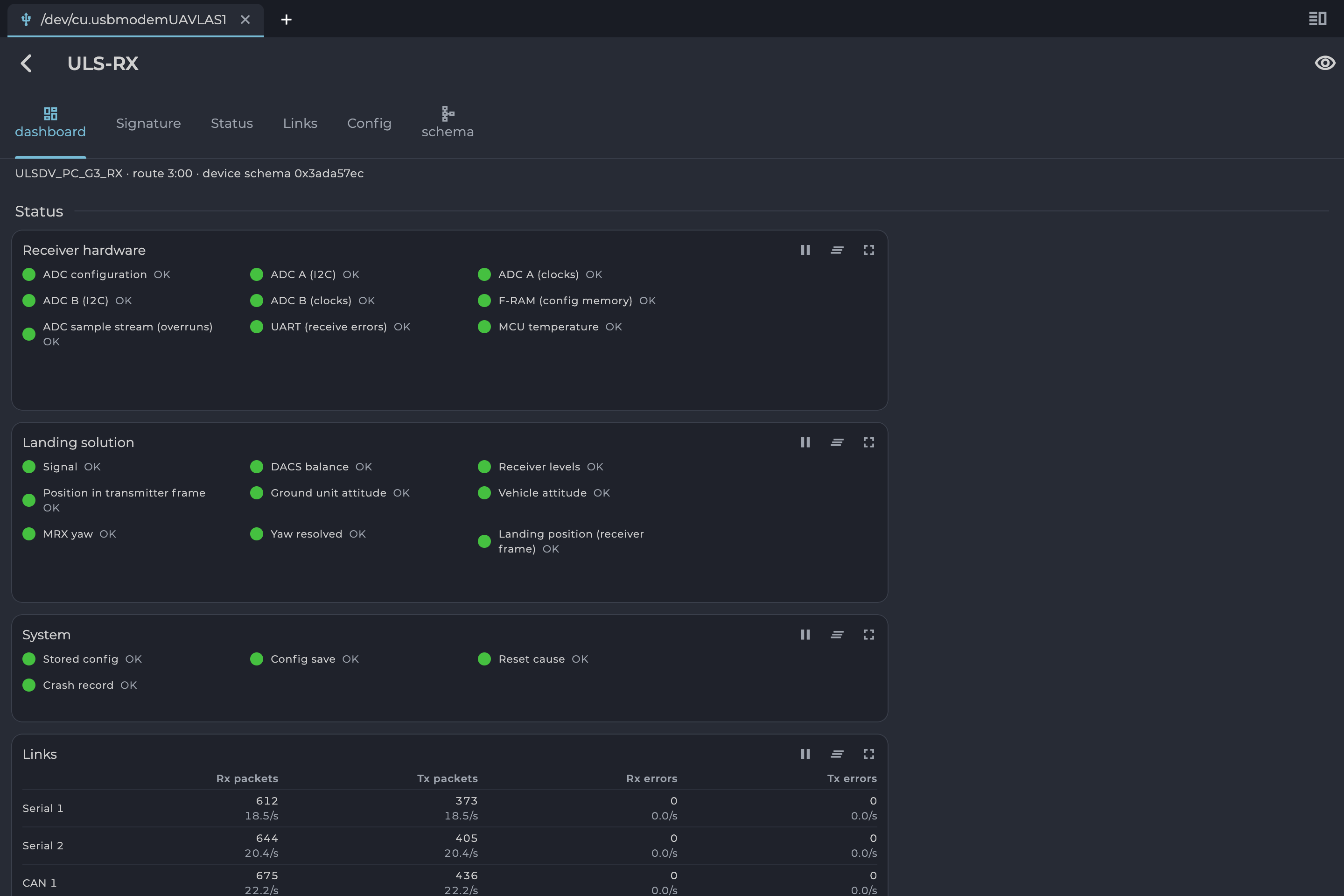
Figure: Receiver Dashboard
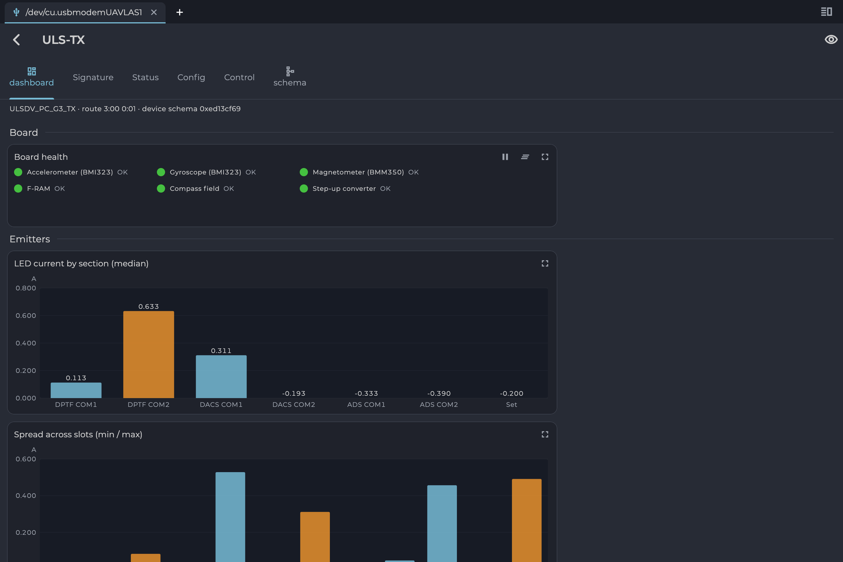
Figure: Transmitter Dashboard
The application reads the device only while the dashboard is on screen, and leaving the tab stops the updates. Widgets that build up history have the first two of these buttons:
| Button | Action |
|---|---|
| Pause / Resume | Freezes the widget so you can study it. |
| Clear | Discards the history collected so far. |
| Fullscreen | Opens the widget across the whole window. Use the back arrow to return. |
Table: Widget Card Buttons
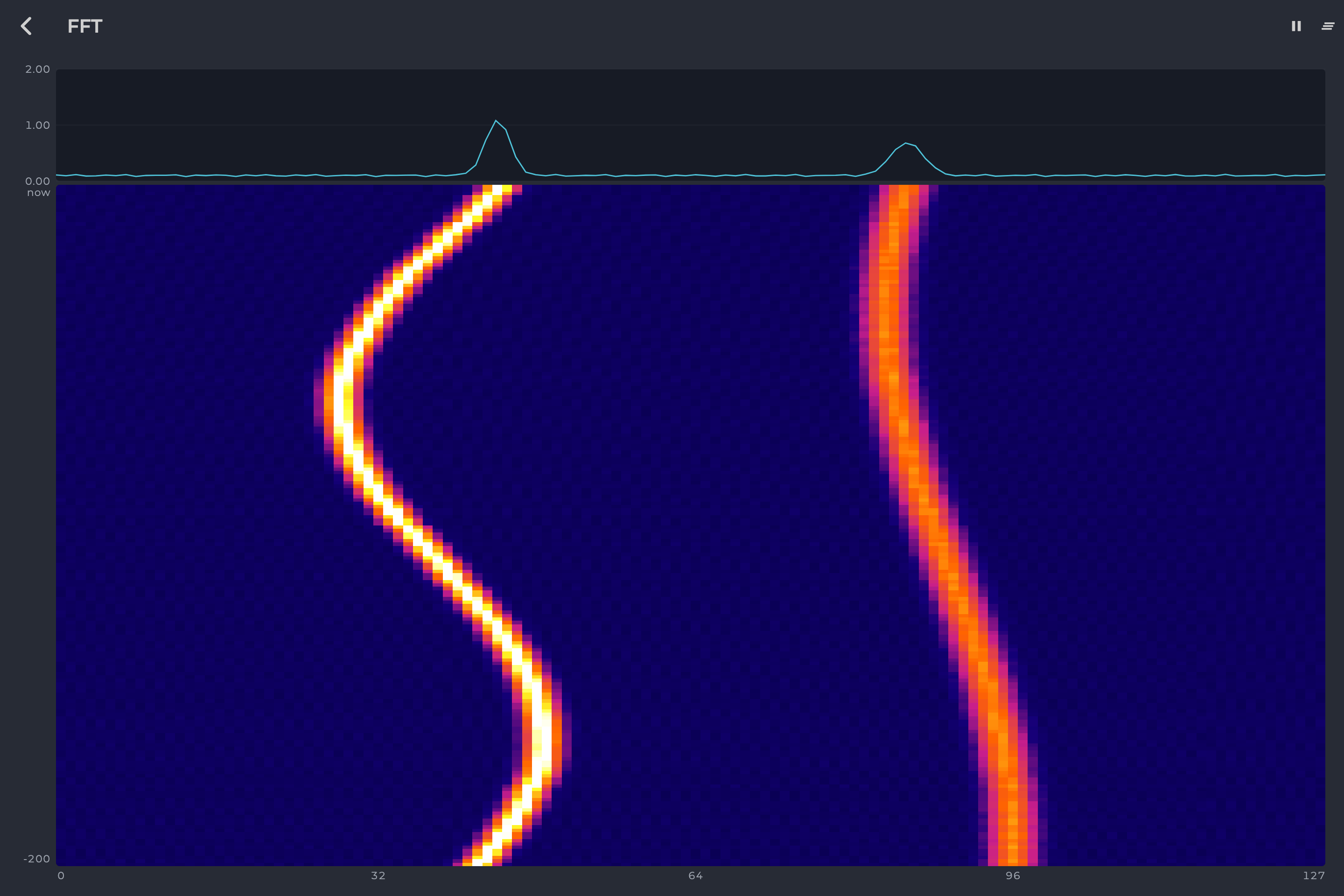
Figure: Widget in Fullscreen
Widget Reference
There are eleven kinds of widget. A card’s title and contents come from the device, so this chapter describes each kind and names the example shown.
Health Lamps
One lamp per part of the board, showing what works. Examples: “Receiver hardware”, “Board health”.
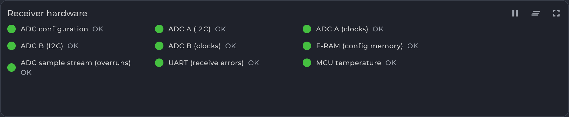
Figure: Health Lamps, Receiver

Figure: Health Lamps, Transmitter
| Color | Meaning |
|---|---|
| Green | The part works and has not failed since the device started. |
| Amber | The part works now but has failed since the device started. |
| Red | The part is failing now. |
Table: Health Lamp Colors
Counters Table
A table of counters, one row per interface or item. Example: “Links”.
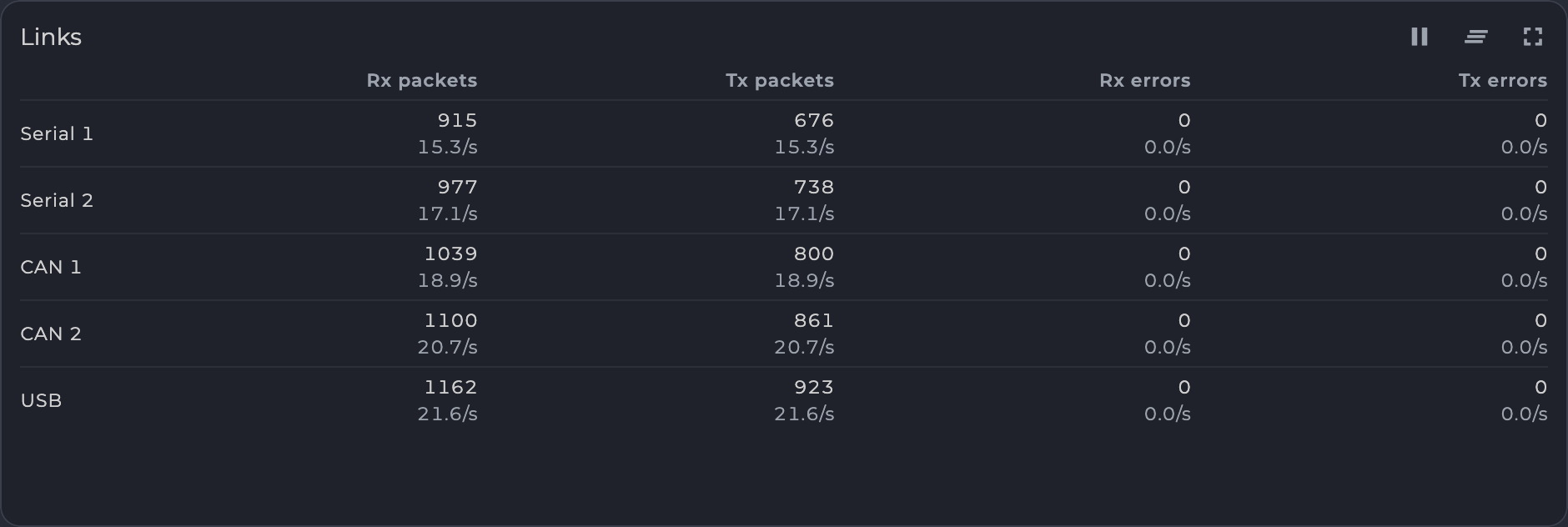
Figure: Counters Table
Each cell shows the running total and, beneath it, its rate per second. A count that goes backwards, as after a restart, starts the rate over.
| Display | Meaning |
|---|---|
| Error column, amber | The error count is not zero. |
| Error column, red | Errors are still rising. |
| Grey row | All counters are zero, so the interface is not in use. |
Table: Counters Table Colors
Receiver Panel
A receiver’s main parameters on one card. A device may show only some of these parts. Example: “Receiver”.
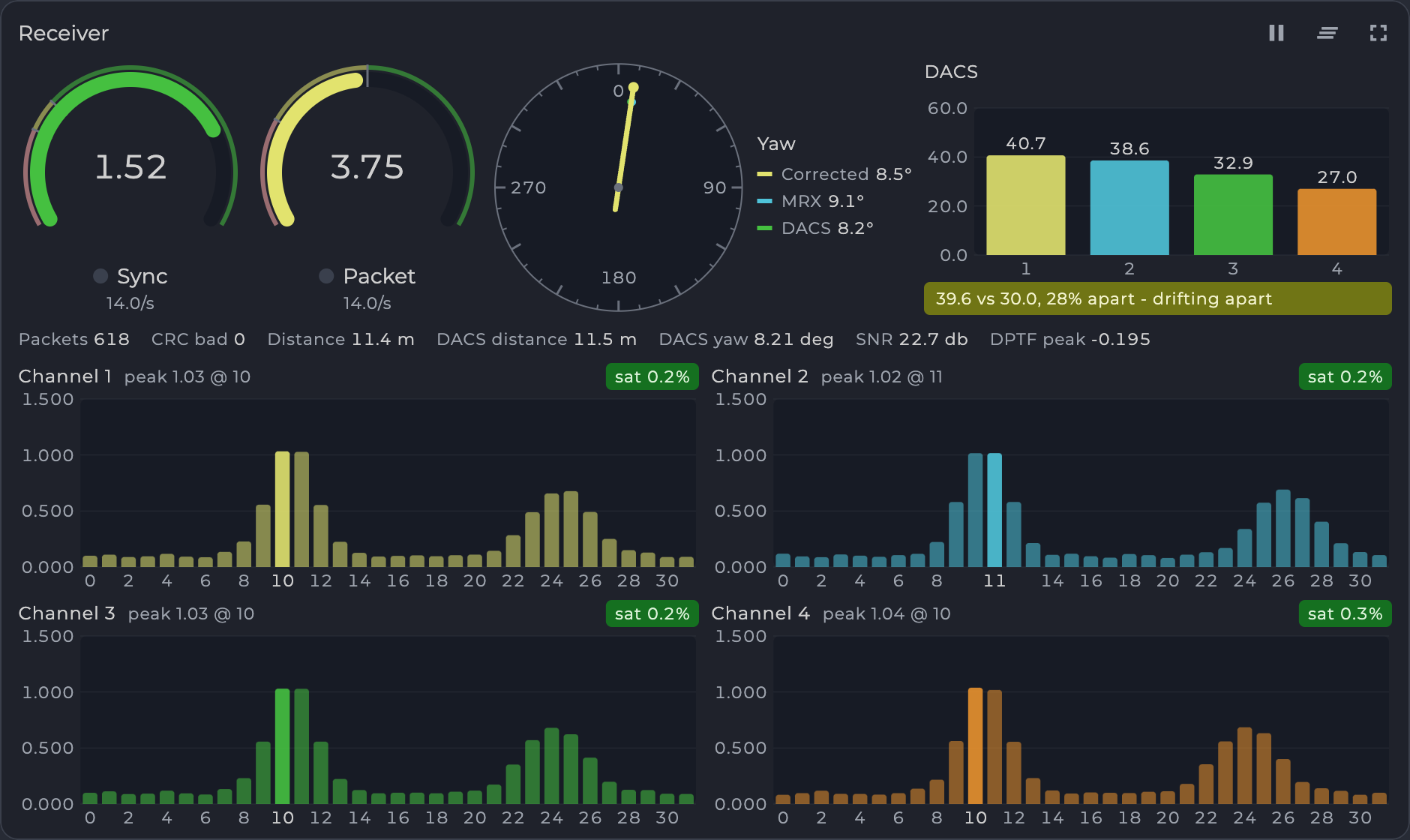
Figure: Receiver Panel
| Part | Shows | How to read it |
|---|---|---|
| Gauges | Signal quality values, with a lamp and a rate per second. | Red is below the weak limit, amber is between, green is at or above the good limit. The lamp lights when something is received. A grey value is stale: nothing has been received lately, and the device is only keeping its last value. |
| DACS | One bar per DACS signal, with a balance message. | The two pairs of signals should match. Green reads “pairs balanced”, amber reads “drifting apart”, red reads “receiver or DACS signal fault”. |
| Yaw | Yaw values as needles on one compass, 0 at the top, turning clockwise. | The bold needle is the first value (in the figure, Corrected). Needles that agree point the same way. |
| Channels | One bar chart per channel, with the peak picked out, all on one scale. | Compare the channels at a glance. The header chip shows saturation: green has headroom, amber starts at 80 % of the limit, red means the channel clips. |
Table: Receiver Panel Parts
Position Chart
An X-Y plot of one position with a fading trace of where it has been. The readout below gives the current values. Example: “Relative position”.
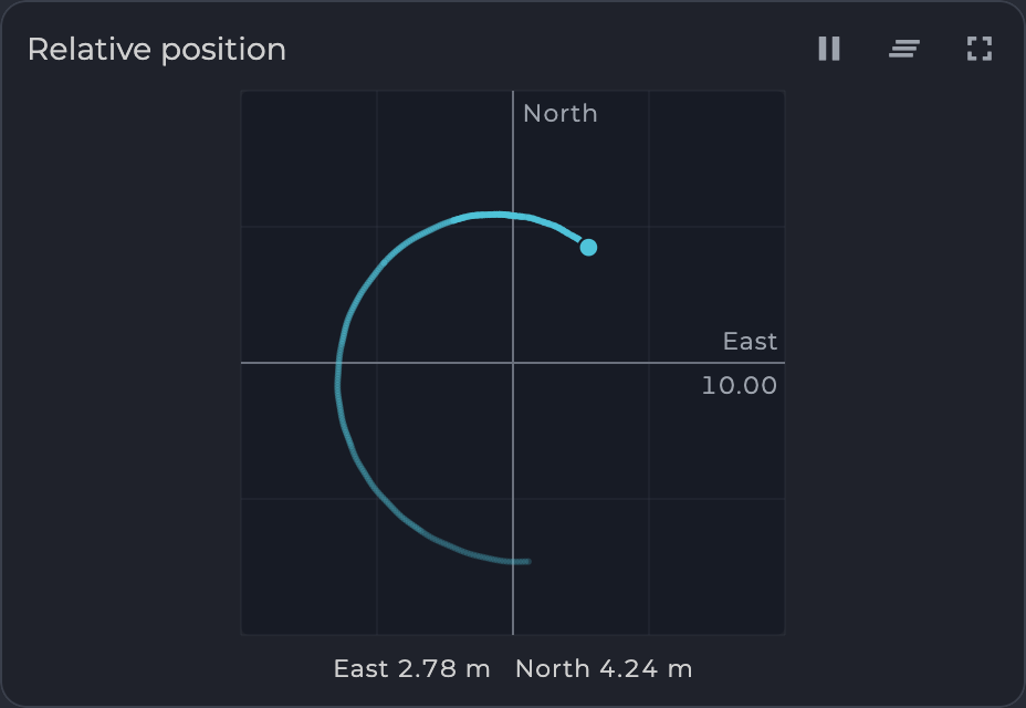
Figure: Position Chart
Line Chart
A scrolling chart of values over time, newest at the right. The legend names each line and gives its current value and unit. Examples: “Distance”, “Relative position NED”.
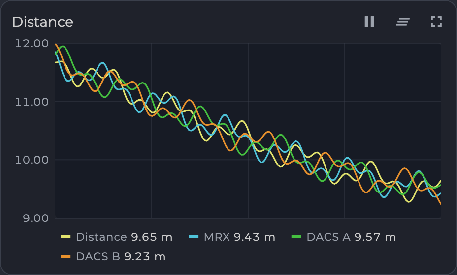
Figure: Line Chart, Distance
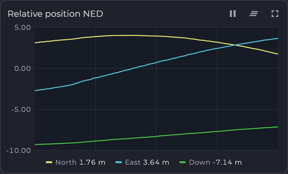
Figure: Line Chart, Relative Position
Bar Chart
One bar per value, updated live. The columns are numbered or named by the device, and some cards print each value above its bar. A value below the bottom of the axis has a number but no visible bar. Examples: “DACS power”, “LED current by section (median)”, “Satellites”.
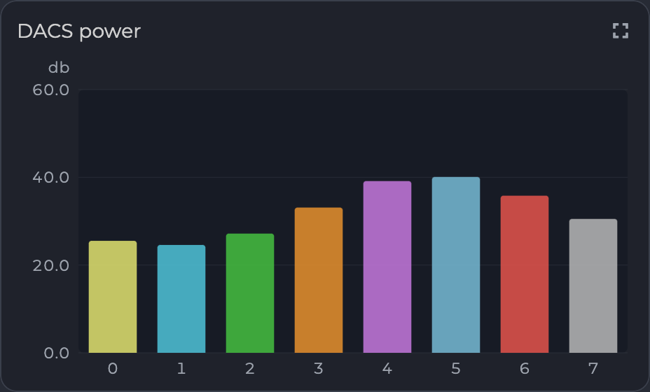
Figure: Bar Chart, DACS Power
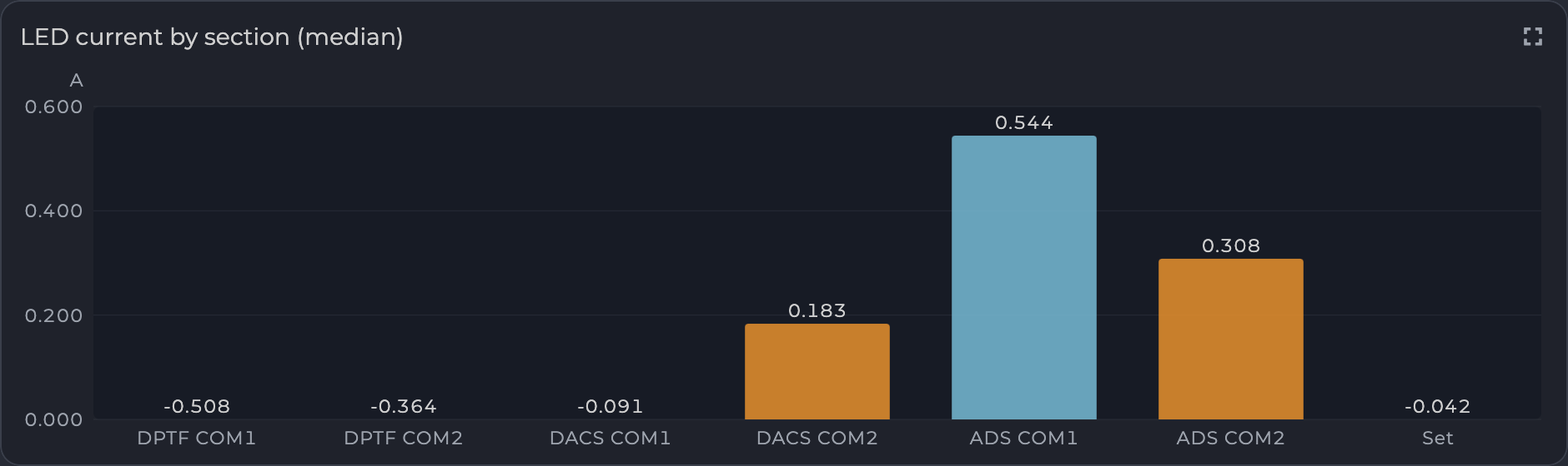
Figure: Bar Chart, LED Current
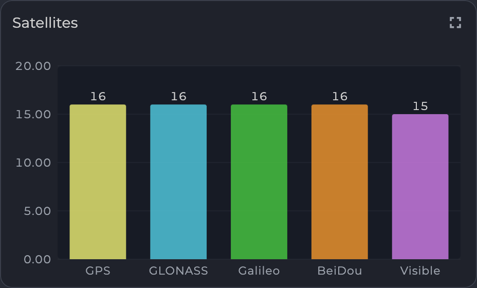
Figure: Bar Chart, Satellites
Spectrum Waterfall
A spectrum over time. The top chart shows the spectrum now. Below it, each row is an earlier spectrum, with the newest at the top (“now”), and brighter colors mean a stronger signal. A peak that moves sideways as you read down is a signal changing frequency over time. Example: “FFT”.
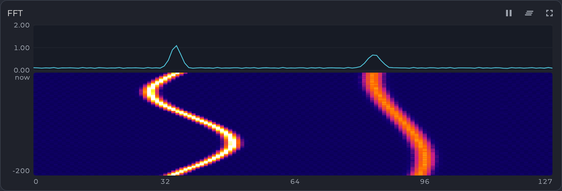
Figure: Spectrum Waterfall
Pulse Capture
The last capture of a pulse-position packet, not a history. Example: “DPTF receiver - last capture”.
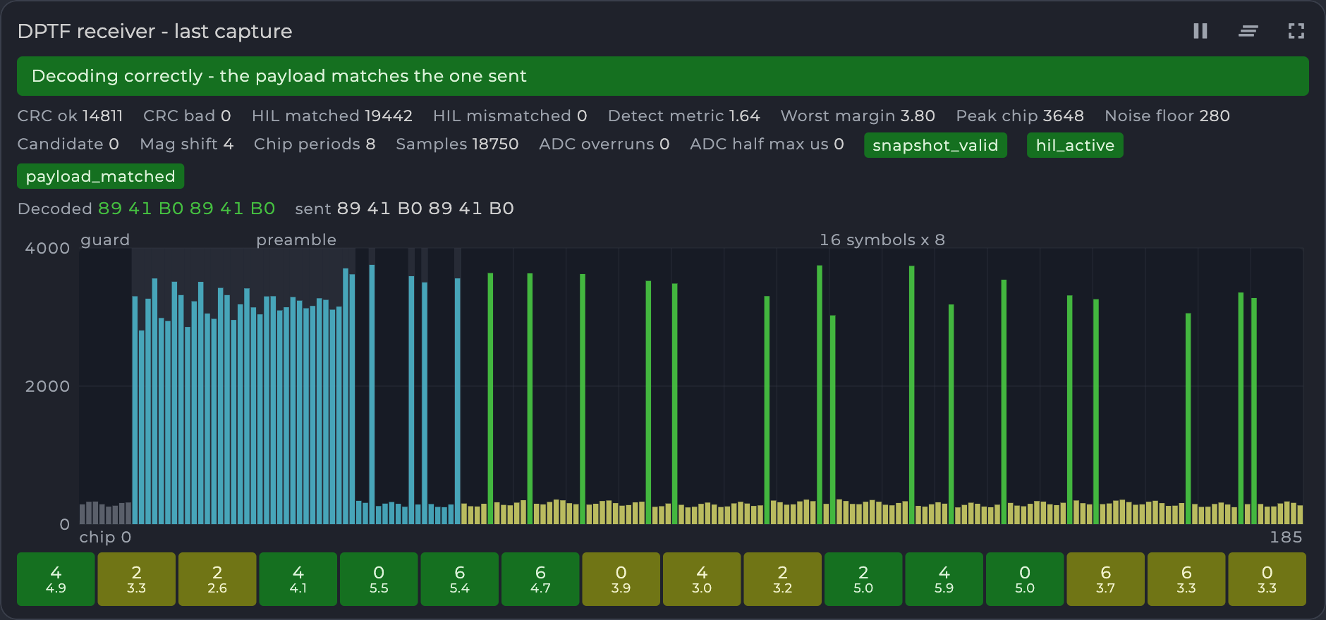
Figure: Pulse Capture
| Part | Shows | How to read it |
|---|---|---|
| Status banner | The verdict on the capture. | For example “Decoding correctly - the payload matches the one sent”, or in red “Decoded payload does NOT match the one sent”. |
| Readout and chips | Values and flags from the device. | Names come from the device. A chip is a flag that is set. |
| Decoded / sent | The decoded payload bytes, and the bytes sent when the device knows them. | The two should match. |
| Envelope chart | Magnitude of each chip: guard, preamble, then the symbols. | Each symbol should have exactly one bright chip. The chosen chips are picked out in color. |
| Symbol boxes | Each symbol’s decoded value and its margin. | The margin is how far the winning slot beat the runner-up. Green is decisive, amber is less so. |
Table: Pulse Capture Parts
IMU Charts
One inertial sensor source at a time, chosen by tab. Example: “IMU sources”, with Internal, External primary and External secondary sources. Hidden sources keep recording.
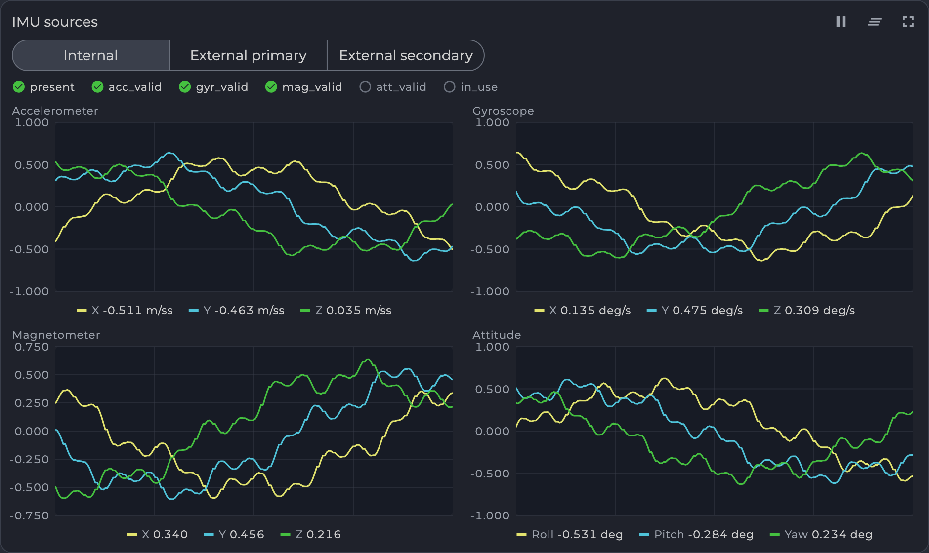
Figure: IMU Charts
| Part | Shows |
|---|---|
| Status lamps | The source’s status bits. A filled lamp means the bit is set. |
| Accelerometer | X, Y and Z acceleration. |
| Gyroscope | X, Y and Z rotation rate. |
| Magnetometer | X, Y and Z magnetic field. |
| Attitude | Roll, pitch and yaw. |
Table: IMU Charts Parts
Compass Calibration
Shows the magnetometer’s readings on three planes (X-Y, X-Z, Y-Z) and calculates a calibration from them. Sources appear as tabs. A source calibrated by another device can be captured and checked, but not written.
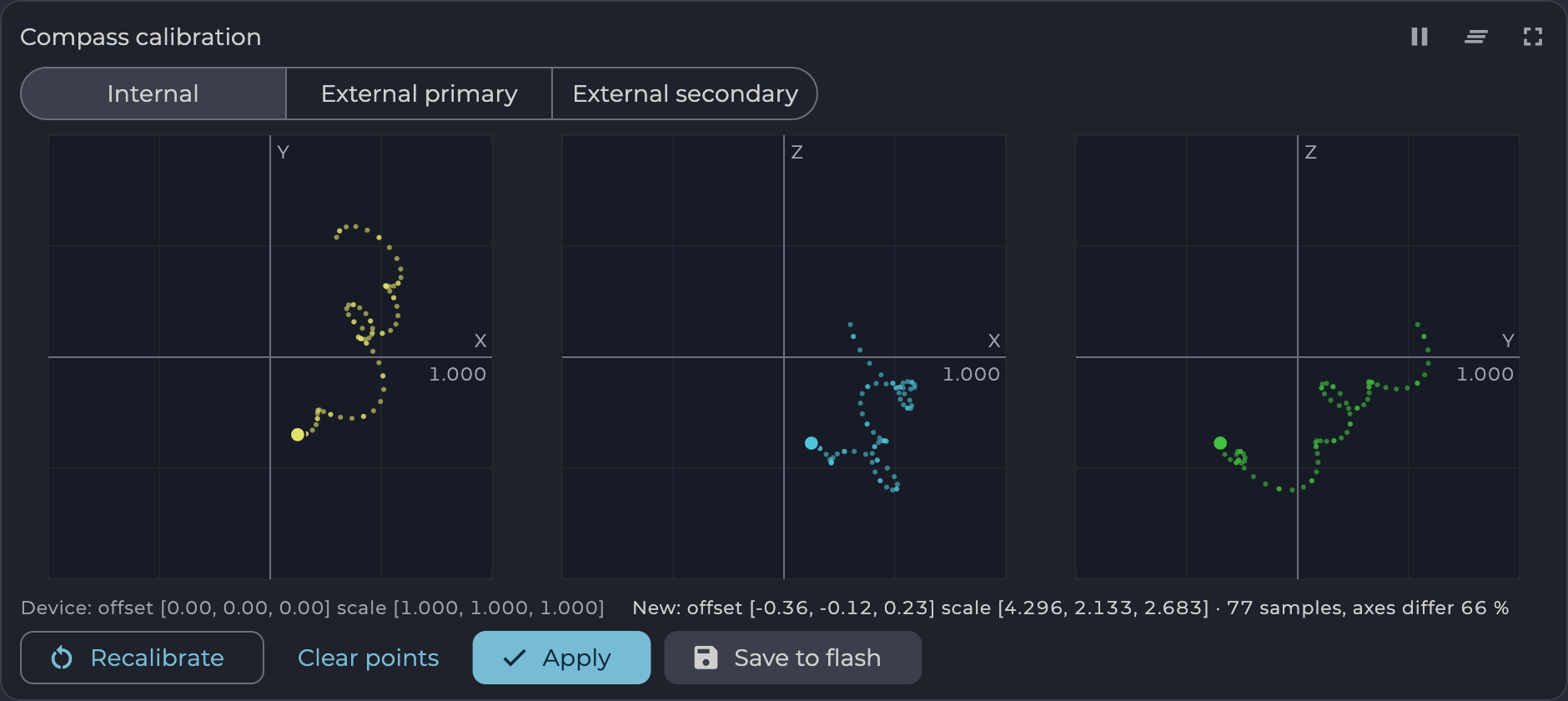
Figure: Compass Calibration
| Value | Meaning |
|---|---|
| Device | The offset and scale the device is using now. |
| New | The offset and scale calculated from the captured points. |
| Samples | How many points have been captured. |
| Axes differ | How much the three axes disagree. Lower is better. |
Table: Compass Calibration Values To calibrate:
- Select Recalibrate and confirm. The calibration in use is reset to offset 0 and scale 1, so the device reports the raw field. Flash keeps the old calibration until you save.
- Turn the board through all axes, as the message on the card asks. The points should build up evenly in all three plots.
- Select Apply to write the new calibration to the device.
- Select Save to flash and confirm. This saves every setting in that object as the device holds it now.
Clear points discards the captured points so you can start over without resetting the calibration.
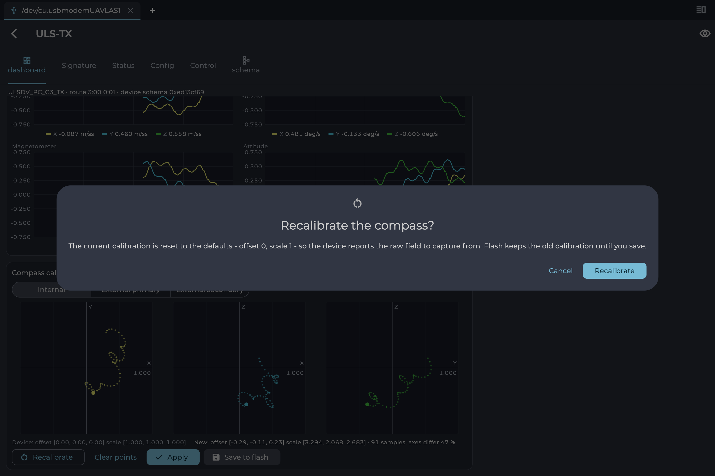
Figure: Recalibrate Confirmation
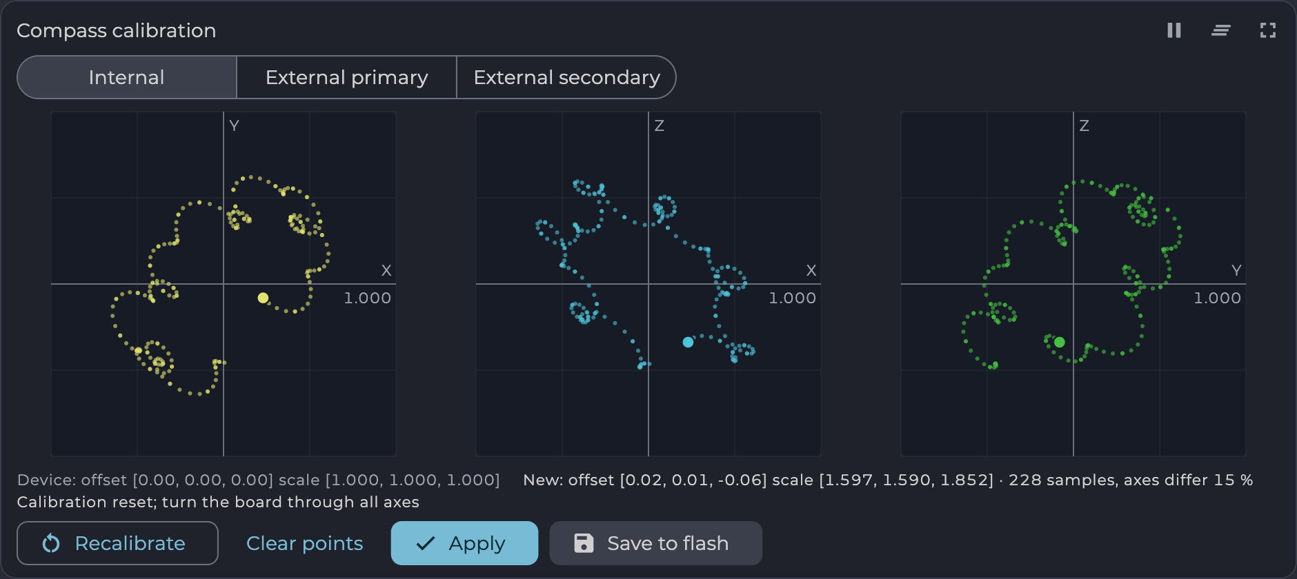
Figure: Capturing Points After a Reset
Position Map
A position on a map, with the marker pointing along the heading. Map tiles come from OpenStreetMap, so they need internet access. The i button at the bottom right shows the map attribution. Example: “GNSS position”.
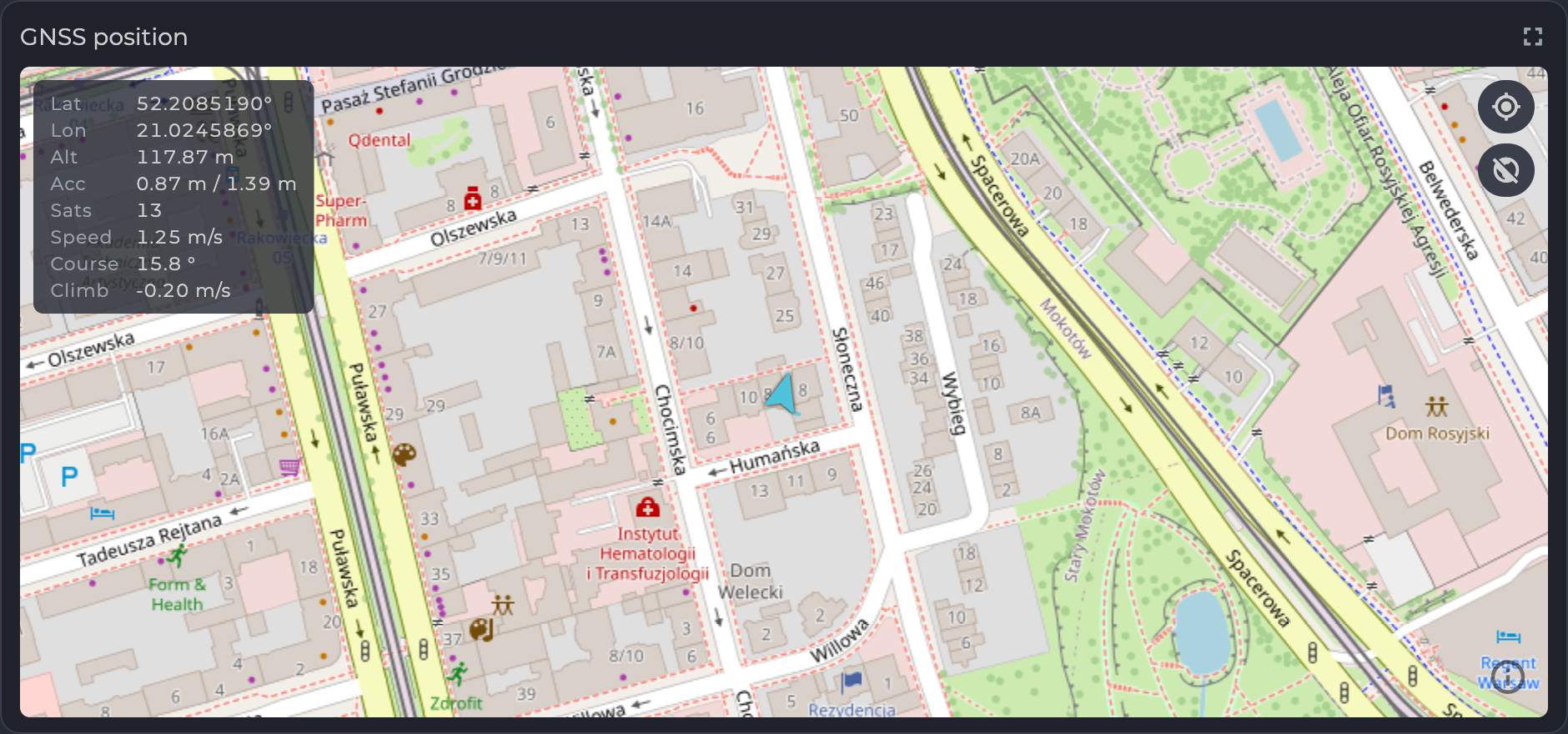
Figure: Position Map. Map data © OpenStreetMap contributors
| Value | Meaning |
|---|---|
| Lat, Lon | Latitude and longitude. |
| Alt | Altitude. |
| Acc | Horizontal and vertical accuracy. |
| Sats | Satellites used. |
| Speed, Course, Climb | Ground speed, direction of travel and vertical speed. |
Table: Position Map Readout Two buttons sit at the top right. One re-centers the map (tooltips “Center on the fix” and “Following the fix”). The other switches the background (tooltips “Coastline only” and “Map tiles”). Without a position, the readout shows “No fix”, or “No fix — last position” when an earlier position is known.
Diagnostics
Event Log
The log tab appears at the Service level on devices that keep a log. Select Read to fetch it.
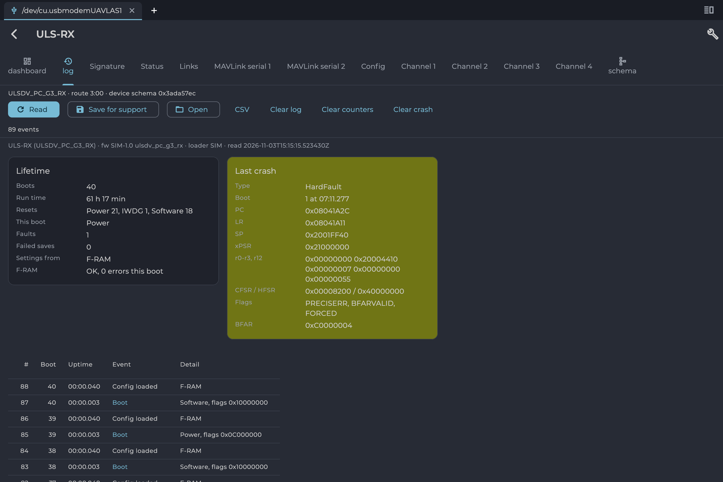
Figure: Event Log
| Part | Shows |
|---|---|
| Lifetime | Boots, run time, reset causes, faults, failed saves, and where settings came from. |
| Last crash | Details of the last crash for engineering analysis, when one is recorded. |
| Event table | #, Boot, Uptime, Event and Detail for each event. |
Table: Event Log Contents
| Button | Action |
|---|---|
| Read | Reads the log from the device. |
| Save for support | Saves the log to a file to send to UAVLAS support. |
| Open | Opens a saved log. |
| CSV | Exports the events as a CSV file. |
| Clear log, Clear counters, Clear crash | Erase that data from the device. Save it first if you may need it. |
Table: Event Log Buttons
ADC Capture
The capture tab records raw receiver samples, for engineering analysis. It appears at the Developer level on devices that support it. Set the trigger and channels, select Arm, and wait for the capture to download. Use Save to keep it as a .ulscap file, or Open to view a saved one.
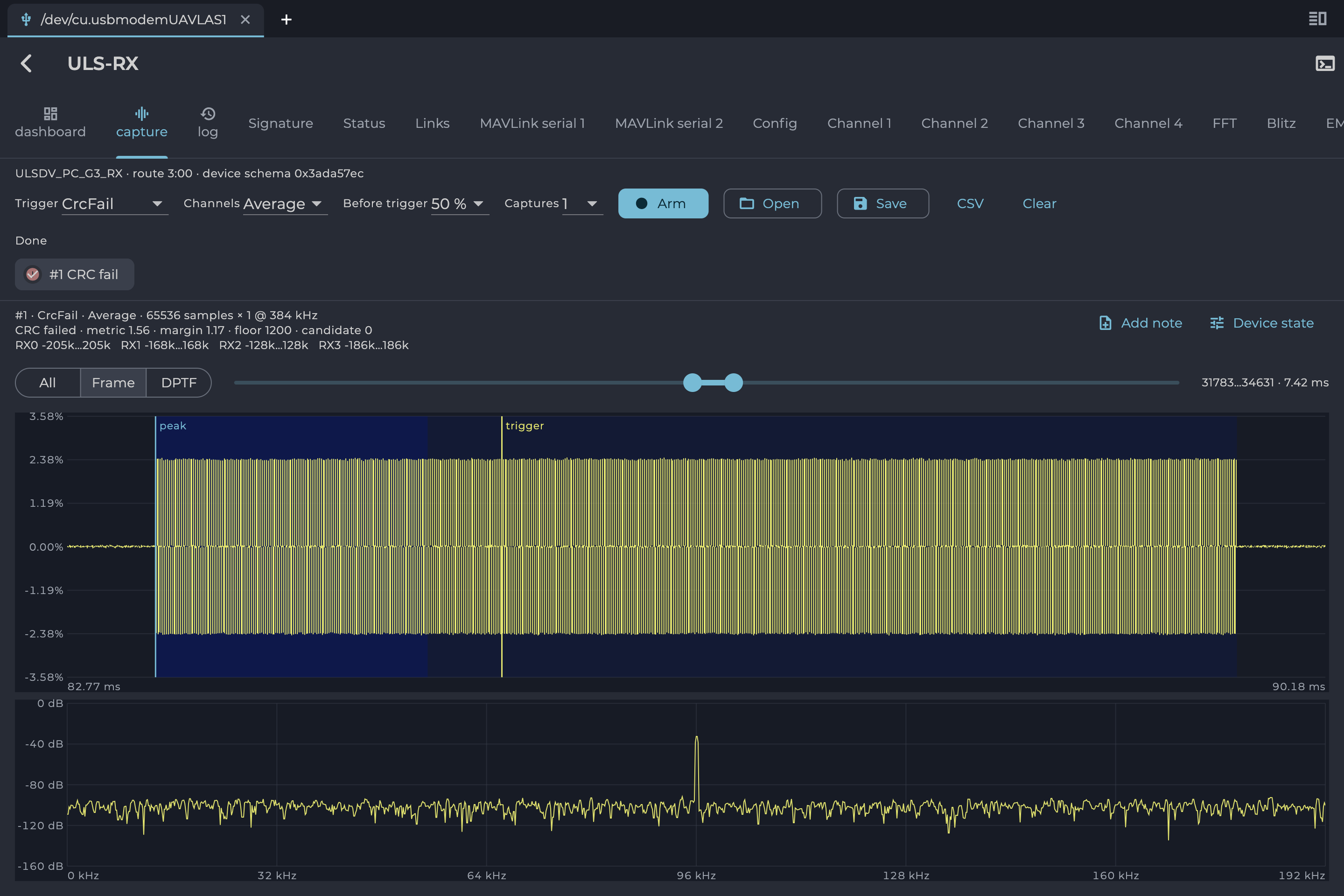
Figure: ADC Capture
Packet Log
The packet log shows the raw traffic on a port, for debugging. On the connection page, select the terminal icon on a row (tooltip “Raw packet log”). This opens the port for logging only, without joining the bus.
Each line shows direction, bytes, time and length. To send a packet, enter it in Packet (hex) and select Send.
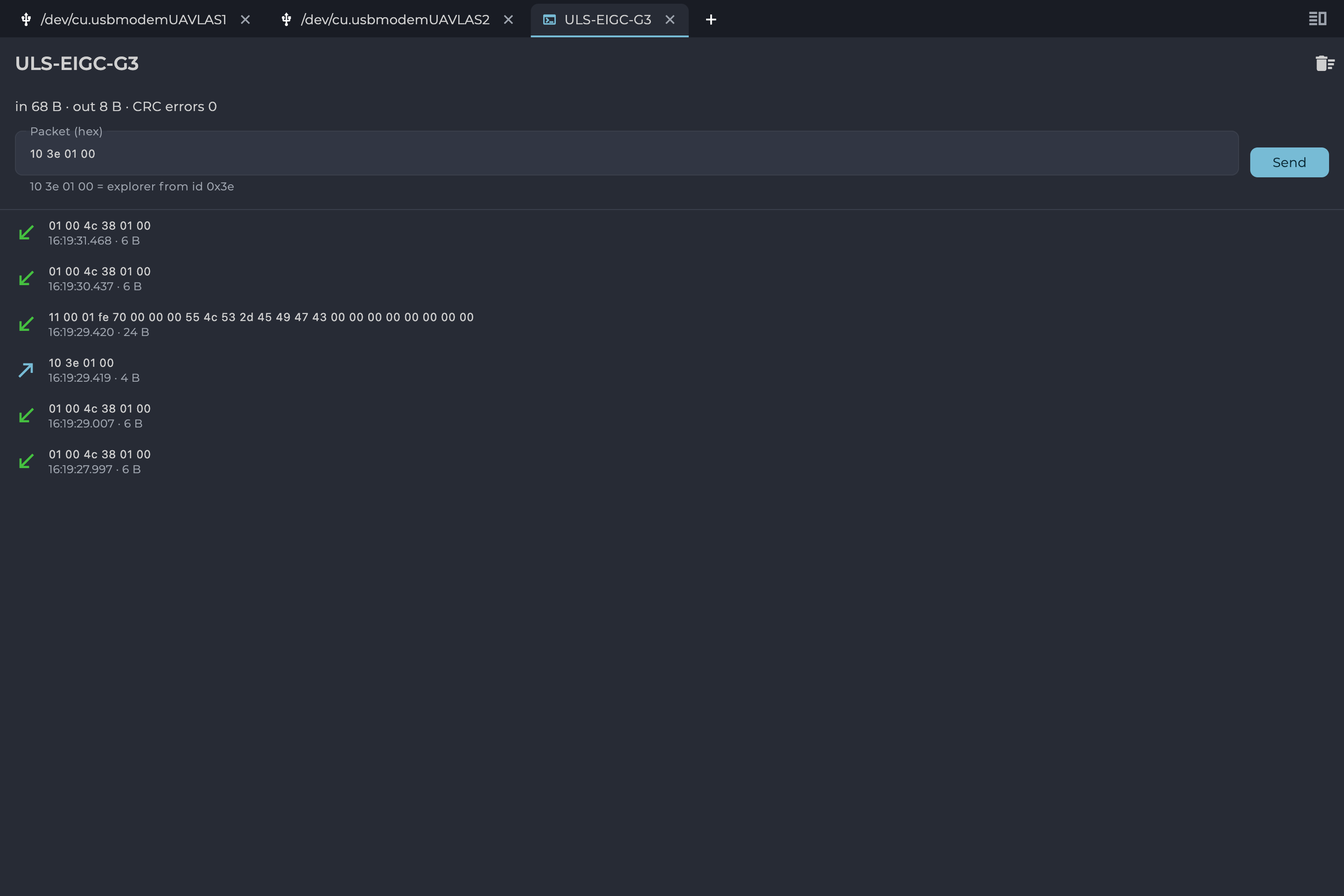
Figure: Packet Log
Remote API
On desktop, ULSToolsX can let another program on the same computer use its open link, so scripts can read and write devices without closing the application. It is off by default. Turn it on with the network icon in the app bar. It listens only on this computer. For the protocol description, contact UAVLAS support at support@uavlas.com.
Troubleshooting
| Message or symptom | What it means | What to do |
|---|---|---|
| macOS refuses to open the application | The build is unsigned. | Right-click the application and choose Open. |
| “No devices found” | The search found nothing on this card. | Check the cable and power, then use the refresh button. |
| “Not available on this platform” | This connection type does not work on your platform or browser. | In a browser, try Chrome or Edge on a desktop computer. Otherwise use another connection type or install the application. |
| “Looking for devices…” does not clear | No device has answered on the bus. | Check power and the baud rate. Select Explore. |
| “No schema — signature only” | The device gave no description of itself. | Update its firmware. If it continues, contact support. |
| “The device stopped answering; showing the last values read. Waiting for it to come back…” | The device went silent. Values on screen are old. | Check power and the connection. The page recovers by itself when the device returns. |
Table: Connection and Device Messages
| Message | What it means | What to do |
|---|---|---|
| “Could not reach the firmware server” | No connection to the UAVLAS server. | Check internet access and select Retry, or load a file. |
| “Nothing published on this channel yet” | The channel has no builds. | Choose another channel. |
| “This is not a firmware bundle.” | The chosen file is not a firmware file. | Choose a .ulsbndl file. |
| A message ending “failed its MD5 check.” | The file is damaged. | Download it again. |
| “The device did not restart into its loader.” | The device did not enter update mode. | Power cycle it and try again. |
| “The device stopped answering (…)” | Communication was lost during the update. | Check power and the connection, then try again. |
| “Lost the device (…)” | The device left the bus during the update. | Check power and the connection, then try again. |
| “The device refused the key (…)” | The device rejected the update’s unlock step. | Try again. If it continues, contact support. |
| “The device reported an error (…)” | The device reported a failure during the update. | Try again. If it continues, contact support. |
| “The device did not report its serial number, which is its key.” | The update cannot start without the serial number. | Power cycle the device and try again. |
Table: Firmware Messages